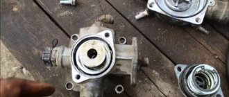
Main brake valve KAMAZ EURO
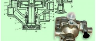
On modern trucks produced by the KamAZ company, the Euro standard State Customs Committee is installed. The structure of the main brake valve is shown in the figure below.
Construction of the KamAZ main brake valve
1 — top cover of the valve body; 2; 19 — screws securing the structure; 3;18 - washers for fastening on a spring basis; 4 — pushing device; 5 — GTK bushing; 6 — body base of the control lever; 7 — screw for adjusting the gas turbine engine; 8 — control lever; 9 — fastening nut; 10 — spring plate; 11 - device for maintaining balance; 12 — ring for seal; 13 — GTK piston; eleven; 16; 24; 28 — spring fastenings; 15 — hull base of the upper part of the GTK; 17;29 - support base; 20;32 — base rings; 21 - large diameter piston; 22 — atmospheric valve GTK; 23 - small diameter piston; 25 — body of the lower base; 26;30 - ring parts; 27 — body base of the valve of the lower part of the GTK; 31 — exhaust window of the GTK.
_______________________________________________________________________________
Brake valves and compressor for Kamaz vehicles - disassembly and assembly
Two-section brake valve KamAZ-4310, 55111, 5320, 43118 Dismantling the two-section brake valve KamAZ-4310, 55111, 5320, 43118 - Install the brake valve KamAZ-4310, 55111, 5320, 43118 in a vice with the lever body down - Remove the thrust ring 32 (fig .1) - Remove the outlet window 31, ring 29, spring 28 and valve 27 of the lower section from the lower housing 25 - Unscrew the nuts and washers 18 bolts 19 securing the lower housing 25 and remove the housing from the valve - Remove the spring 24 small piston 23 from the valve body assembled with a pusher and a large piston 21 - Remove the thrust ring 20 of the upper section valve, ring 17, spring 16, valve 15 of the upper section - Unscrew the nuts securing the upper housing to the lever body - Remove the upper housing from the lever housing - Remove the follower piston from the upper housing 13 assembled and spring 14 — Remove the lever housing 6 from the vice — Unscrew the nut 9 and remove the plate 10 and elastic element 11 from the follower piston 13 — Remove the pusher from the lever housing 6 4 — Unscrew the adjusting screw from the lever 8 7 — Wash the brake valve parts in diesel fuel, blow with compressed air and check their technical condition
Fig.1. Brake valve KamAZ-4310, 55111, 5320, 43118 two-section 1 - upper body; 2, 19 - bolts; 3, 18 — spring washers; 4 - pusher; 5 - bushing; 6 — lever body; 7 — adjusting screw; 8 — lever; 9 — nut: 10 — spring plate; 11 — balancing element; 12 — sealing ring; 13 — follower piston; 14, 16, 24, 28 — springs; 15 — valve body of the upper section; 17, 29 — support rings; 20, 32 — thrust rings; 21—large piston; 22—atmospheric valve; 23 — small piston; 25 — lower body; 26, 30—rings; 27 — valve body of the lower section; 31 — exhaust window assembly Brake valve assembly KamAZ-4310, 55111, 5320, 43118 — Install the pusher 4 into the lever body 6 and screw in the adjusting screw 7. — Install the elastic element 11 and the plate into the follower piston 13 (see Fig. 1) 10, screw the fastening nut 9 - Install the upper body in a vice - Install the valve 15 of the upper section assembled with the pusher into the upper housing 1 - Install the spring 16, ring 17, thrust ring 20 on the valve 15 of the upper section - Install a large piston 21 into the upper body , small piston 23 and spring 24. — Install valve 27 of the lower section, spring 28, spring ring 29, exhaust window 31 assembled, thrust ring 32 into the lower housing 25. — Install the lower valve housing 25 onto the upper housing and screw the nuts with spring washers 18 bolts 19 markings - Remove the upper housing assembly with the lower one from the vice - Install the lever housing 6 in the vice - Install the follower piston 13 assembly and spring 14 into the upper valve body. — Install the upper housing assembled with the lower one onto the lever body — Screw the nuts securing the upper housing to the lever body. — Put on the protective shell — Remove the brake valve KamAZ-4310, 55111, 5320, 43118 from the vice — Test the brake valve for operability and tightness
Brake valve for controlling the parking brake system KamAZ-4310, 55111, 5320, 43118 Dismantling the valve KamAZ-4310, 55111, 5320, 43118 for controlling the parking brake system - Install the brake valve KamAZ-4310, 55111, 5320, 43118 in a vice with the lid up - Remove the screws 3 (Fig. 2) with washers 4, 5, 6 securing the valve cover 7 to the body 28 - Remove the cover assembly with handle 1 and spring 2 from the body - Unscrew handle 1 from cover 7 - Remove pin 9 from rod 18, remove washer 10 , cap 11 - Remove from the body 28 the thrust ring 12, guide 13, ring 14, spring 15, rod 18, washer 17, ring 16, plate 19, spring 20, piston 21 assembly - Remove the thrust ring 26 from the piston 21, remove valve ring 22, body 23, support washer 24, spring 25 - Remove valve body 28 assembled with washers 29 and ring 27 from a vice - Wash the brake valve parts Kamaz-4310, 55111, 5320, 43118 in diesel fuel, blow with compressed air and check their technical condition
Fig.2. Kamaz-4310, 55111, 5320, 43118 car crane for controlling the parking brake system 1 - handle; 2, 8, 15, 20, 25 — springs; 3—screw; 4, 6, 10, 17, 29 — washers; 5—spring washer; 7 - cover; 9 - pin; 11 — guide cap; 12, 26 — thrust rings; 13 - guide; 14, 16, 27—rings; 18 — rod; 19 — spring plate; 21 - piston; 22 — valve ring; 23 — valve body; 24 — support washer; 28 - housing Assembly of the control valve for the parking brake system Kamaz-4310, 55111, 5320, 43118 - Install the piston 21 ring 22 valves, valve body 23, support washer 24, spring 25, thrust ring 26. - Install the housing 28 assembled with a vice , soft washers 29 and ring 27 in a jaw vice - Install the piston 21 assembly, rod 18, spring 20, plate 19, washer 17, ring 16, spring 15, guide 13 with ring 14 and thrust ring 12 into the valve body. - Install into the body of the brake valve Kamaz-4310, 55111, 5320, 43118 guide cap 11 and washer 10 - Install pin 9 into the rod - Screw handle 1 into valve cover 7 - Install cover 7 assembled with handle and spring 2 onto valve body 28 - Screw screws 3 fastening the cover with washers into the valve body - Remove the brake valve from the vice - Adjust the gap between the valve cover and the washer Brake compressor for Kamaz-4310, 55111, 5320, 43118
Fig.3. Air brake compressor KamAZ-4310, 55111, 5320, 43118 1, 8, 22 - gaskets; 2 — lower crankcase cover; 3, 10. 13 — spring washers; 4, 11, 25 — bolts; 5 - crankcase; 6 — crankshaft; 7, 37 — bearings; 9 - cover; 12—key; 14, 21, 26 — nuts; 15 — cylinder block; 16 — intake valve seat; 17 — intake valve guide; 18 — intake valve: 19, 34 — springs; 20 — compressor head assembly; 23 — piston with connecting rod; 24 — reflector plate; 27 — cotter pin; 28 — liner; 29— connecting rod cover; 30— thrust nut; 31 — lock washer; 32, 36 — thrust rings; 33 - seal; 35 — drive gear wheel Disassembling the Kamaz-4310, 55111, 5320, 43118 compressor Fig. 4. Compressor head Kamaz-4310, 55111, 5320, 43118 1 - discharge valve plug; 2.6 - gaskets; 3 - spring; 4—discharge valve; 5 — discharge valve seat; 7— compressor head - Unscrew the nuts 21 (Fig. 3) securing the compressor head 20 - Remove the head 20 of the Kamaz-4310, 55111, 5320, 43118 compressor assembled with the discharge valves, head gasket 22, inlet valve springs 19 - Remove from the block sockets cylinders, intake valves 18, intake valve guides 17, press out the seats 16 - Secure the compressor head 20 in a vice - Unscrew the plugs 1 (Fig. 4) of the discharge valves and remove the gaskets 2 from the head of the plugs 2, valve springs 3, discharge valves 4, turn out the seats 5 valves and remove the gaskets 6 of the seats - Remove the head 7 from the vice - Unlock the lock washer 31 (see Fig. 3) and unscrew the nut 30 securing the crankshaft drive gear, remove the thrust ring 32, seal 33, seal spring 34 - Use a puller to remove the gear wheel 35 (see Fig. 3) of the drive and remove the key 12 from the groove of the crankshaft 6 - Turn the KamAZ-4310, 55111, 5320, 43118 compressor on the stand to a position convenient for removing the bottom cover 2 - Remove the bolts 4 with spring washers 5 , remove cover 2, gasket 1 - Turn the crankshaft to a position convenient for unscrewing the nuts of the connecting rod bolts - Remove the cotter pin 27, unscrew the nut 26 of the connecting rod bolts 25 - Remove the connecting rod cover 29, remove the piston 23 assembled with the connecting rod from the cylinder. — Remove the liners 28 from the connecting rods, align the cover 29 with the connecting rod and connect without tightening with bolts 25 with nuts 26 — Turn the Kamaz-4310, 55111, 5320, 43118 compressor on the stand with the cylinder block facing up — Unscrew the bolts 11 with spring washers 10. Remove the cover 9 with gasket 8 - Unscrew the nuts 14 with spring washers 13 securing the cylinder block 15 to the crankcase 5 of the compressor. Remove the cylinder block with reflector plates 24 - Remove the thrust ring 36, press the crankshaft with bearings out of the compressor crankcase 5 - Install piston 1 (Fig. 5) with the connecting rod assembly in a vice Fig. 5. Piston with connecting rod of compressor KamAZ-4310, 55111, 5320, 43118 assembled 1 - piston with connecting rod assembly; 2 - bushing; 3 — thrust ring; 4 — piston pin; 5—compression ring; 6 - piston; 7—oil scraper ring; 8 - connecting rod assembly with cover - Remove from piston 6 compression 5 and oil scraper 7 rings, thrust ring 3 of piston pin - Remove connecting rod assembly with piston from a vice - Press out piston pin 4 and disconnect piston 6 from connecting rod 8 - Install connecting rod 8 in vice, press out bushing 2 from the upper head of the connecting rod - Remove the connecting rod from the vice - Wash the Kamaz-4310, 55111, 5320, 43118 compressor parts in diesel fuel, blow with compressed air and check their technical condition. Technical conditions for fault detection and repair of Kamaz-4310 compressor parts , 55111, 5320, 43118
Fig. 6 Compressor cylinder block KamAZ-4310, 55111, 5320, 43118 (Fig. 6). The following are not allowed: - cracks, breaks and holes; — scuffs and marks on the inner surface A of the cylinders; — diameter C under the intake valve seat is more than 17.027 mm; — non-flatness of the landing surfaces B under the crankcase and the compressor head is more than 0.1 mm. If surface A of the cylinders wears by more than 0.02 mm in diameter, it is necessary to bore the cylinders to a repair size or liner them. Compressor housing Kamaz-4310, 55111, 5320, 43118 (Fig. 6). The following are not allowed: - cracks, breaks and holes; — diameter A for ball bearings more than 72.05 mm; — non-flatness of the mating surfaces B under the cylinder block, lower and rear crankcase covers of more than 0.1 mm. Compressor head Kamaz-4310, 55111, 5320, 43118 (Fig. 6). The following are not allowed: - cracks, breaks, holes and dents; — non-flatness of surface A adjacent to the cylinder block is more than 0.1 mm; — risks and traces of wear on the surface of the discharge valve seats — eliminate by lapping or grinding; — the diameter of hole B for installing the discharge valve is more than 28.8 mm. Fig. 7 Crankshaft of the Kamaz-4310, 55111, 5320, 43118 compressor (Fig. 7). The following are not allowed: - cracks and breaks, damage to fillets D; — scuffs and marks on the working surfaces of the shaft; — non-cylindricity of connecting rod journals A more than 0.012 mm; — diameter C for ball bearings and gears is less than 35 mm; — diameter B for the seal is more than 25.05 mm; — the width of the keyway E is more than 5.02 mm; — wear of the connecting rod journals L by more than 0.06 mm from the nominal or repair size Compressor connecting rod KamAZ-4310, 55111, 5320, 43118 (Fig. 7). The following are not allowed: - cracks and breaks; — scuffs and risks on surfaces C; — non-parallelism of the axes of the holes of the upper and lower heads of the connecting rod (bending) over a length of 100 mm is more than 0.1 mm; — misalignment of the axes of the holes in the upper and lower heads of the connecting rod (twisting) over a length of 100 mm of more than 0.15 mm; — non-perpendicularity of surfaces C relative to the axis of the hole of the lower head of the connecting rod over a length of 100 mm is more than 0.15 mm; — diameter L of the lower head of the connecting rod is more than 3.02 mm; — diameter B of the connecting rod upper head bushing is more than 12.507 mm. If the connecting rod upper end bushing becomes loose, replace the bushing. When replacing a bushing, drill an lubrication hole in it and turn it to the nominal size. Sort the connecting rods into groups every 0.003 mm according to the smaller hole diameter
Fig. 8 Discharge valve plug (Fig. 8). The height of 1 plug is not allowed to be less than 31.5 mm. Kamaz-4310, 55111, 5320, 43118 rear compressor crankcase cover. The following is not allowed: — non-flatness of the end surface of the cover adjacent to the compressor crankcase is more than 0.15 mm; — cracks or breaks in the cover, except for the ears. Fill cracks and breaks in the lid ears and clean the weld seams. Seal (Fig. 8). Not allowed: - cracks; - nicks, risks at end A; — diameter B is less than 24.94 mm. Compressor drive gear (Fig. 8). The following is not allowed: - thickness A of the tooth along the chord of the pitch circle is less than 4.2 mm; — width B of the keyway is more than 5.15 mm. Compressor piston Kamaz-4310, 55111, 5320, 43118 (Fig. 8). The following are not allowed: - nicks, scuffs and marks on the working surface of the piston; — wear of the diameters L and C of the piston by more than 0.015 mm from the nominal or repair dimensions of the piston. Repair size pistons are marked on the outer surface of the bottom; — diameter B of the hole in the piston boss for the pin is more than 2.5 mm.
Assembling the Kamaz-4310, 55111, 5320, 43118 compressor - Install connecting rod 8 (see Fig. 5) in a vice - Press bushing 2 into the upper head of the connecting rod. - Remove the connecting rod from the vice - Select groups of piston pins 4 to pistons 6 and connecting rods with pressed bushings - Install the connecting rod 8 into the piston 6 and into the combined holes of the upper head of the connecting rod and the piston boss, press in the piston pin 4 selected in accordance with transition 33, having previously lubricated it with engine oil - Install the connecting rod assembled with the piston with the lower head in a vice - Install on piston 6, oil scraper rings 5, 7 and thrust rings 3 of piston pin 4, selected according to paragraph 5 - Remove the connecting rod assembly with the piston vice - Install head 7 (see Fig. 4) of the Kamaz-4310, 55111, 5320, 43118 compressor in a vice — Install 6 discharge valve seat gaskets into the head 7, screw in 5 valve seats, 4 discharge valves, 3 valve springs, 2 plug gaskets. Screw in the plugs 1 of the discharge valves - Remove the head 7 from the vice - Press the crankshaft 6 with bearings into the crankcase 5 (see Fig. 3) of the Kamaz-4310, 55111, 5320, 43118 compressor, install the thrust ring 36 - Install it in the groove of the crankshaft 6 key 12, put the drive gear 35 and lock washer 31 onto the shaft. Screw on the nut 30 and press the edges of the lock washer 31 into the grooves of the gear nut 30 - Install the seal spring 34, seal 33 and thrust ring 32 into the crankshaft. - Install the crankcase 5 compressors KamAZ-4310, 55111, 5320, 43118 on the stand - Install the rear cover 9 with gasket 8 on the crankcase. Screw in bolts 11 with spring washers 10 - Install cylinder block 15 on crankcase 5 with reflector plates 24, screw nuts 14 with spring washers 13 — Turn the cylinder block with the crankcase assembly on the stand with the crankcase up — Blow compressed air through the cylinders of the block and the connecting rod journals of the crankshaft — Install the piston 23 with the connecting rod assembly onto the connecting rod and into the connecting rod cover 29 into a cylinder. — Install the cover 29 assembled with the liner on the crankshaft journal, having previously lubricated the liner with engine oil — Tighten the nuts 26 with a torque of 15.5–17.5 Nm (1.6–1.8 kg/cm), install cotter pins 27 — Install onto the crankcase 5 of the Kamaz-4310, 55111, 5320, 43118 compressor, the bottom cover 2 with gasket 1 and screw in the fastening bolts 4 with spring washers 3. - Press the 16 intake valve seats into the 15 cylinder block, install the valve guides 17, the intake valves 18 - Install on a block of 15 cylinders, head 20 of the Kamaz-4310, 55111, 5320, 43118 compressor assembled with discharge valves, head gasket 22, springs 19 of inlet valves - Screw the nuts 21 securing the head onto the studs and tighten them.
_______________________________________________________________________________
_______________________________________________________________________________
_______________________________________________________________________________
- Clutch KamAZ-5320 and its components
- Repair of PGU and Kamaz clutch master cylinder
- Gearbox gearbox KamAZ 141
- Gearbox gearbox KamAZ ZF 16
- Gearbox 152 Kamaz with divider
- Gearbox gearbox 154 Kamaz
- Gearbox Kamaz-4308
- Clutch of a Kamaz-4308 car
- Clutch and gearbox KamAZ-65115
- Disassembly and assembly of Kamaz-4310, 55111, 43118 gearboxes
_______________________________________________________________________________
- Cylinder block, head and valves Kamaz-740
- Fuel system of Kamaz-740 diesel engine
- Adjustments and repairs of fuel injection pump Kamaz-740
- Drive axles of the Kamaz-4310 vehicle
- Repair of Kamaz drive axle gearbox
- Rear axle KamAZ-4308
- Axles and suspensions of Kamaz-65115 dump trucks
- Installation of Kamaz cardan shafts and axles
- Repair of Kamaz vehicle transfer case
- Kamaz power steering - adjustments and repairs
- Repair of Kamaz steering gear parts
- Steering parts Kamaz-4308
- Parts of the brake system Kamaz-4308
- Brake system and brake drive Kamaz
- Repair of brake valves and Kamaz compressor
- Suspension Kamaz-4310, 55111, 43118 and their parts
- Frame and suspension of the Kamaz-4308 car
- Cabin details and platform KamAZ-65115
- Cabin components Kamaz-4308
- Platform mechanism of Kamaz vehicles
- Klintsy KS 65719-5K truck crane based on KamAZ-6522 chassis
- Truck crane KC-35719-7-02 based on Kamaz-43118 chassis
- Truck crane Galichanin KC-55713-1K based on KamAZ-65115 6x4
- Ivanovets KS-45717K-1/1R truck crane based on KamAZ-65115 chassis
- Ivanovets KS-3577-3/4 truck crane on KamAZ-43253 4x2 chassis
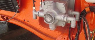
Replacing a two-section brake valve
The two-section brake valve must be replaced if the following malfunctions occur:
1. Violation of the tightness of the tap. An external sign is air leakage through the atmospheric valve at the attachment points of the housing sections.
2. Mechanical damage to the housing, lever, jamming of the pistons, disrupting its normal operation.
Removing a two-piece brake valve
1. Bleed the air from the air drive reservoirs of the front and rear axle brake systems
2. Unscrew the union nuts securing the ends of the pneumatic pipelines to the tees and valve adapter 14 (see figure - brake valve drive)
3. Unpin and remove the pin connecting the rear link fork 12 of the drive with the crane lever
4. Unscrew the nuts of the bolts securing the plate of the upper body of the faucet to the frame brackets and remove the faucet
Installation of two-section brake valve
5. Install the valve on the brackets of the left frame side member and secure with bolts, nuts and spring washers
6. Attach the rear link fork 12 of the drive to the lever, insert the pin and pin it
7. Connect the ends of the pneumatic pipelines to the tees and the valve adapter, screw and tighten the union nuts
8. Start the engine and fill the pneumatic drive of the brake systems with air. Check the tightness of the pipelines and brake valve.
Specifications
Air leakage from the atmospheric valve of the valve, both when the brake pedal is released and when the brake pedal is pressed, is not allowed.
Air leakage in pneumatic drive pipeline connections is not allowed.
9. Check and, if necessary, adjust the stroke of the brake valve lever, which should be 31.1–39.1 mm, in the following order:
— unscrew the locknut of the mid-thrust fork a few turns, unscrew and remove the pin connecting the fork with the pendulum lever, remove the fork from the pendulum lever;
— bring the intermediate lever with the first link to folding and set the required length of the middle link using a threaded fork (by screwing or unscrewing), connect it to the pendulum lever, selecting the gaps in the drive and not allowing forced movement of the brake valve lever. In this case, the full pedal stroke should be 100-140 mm, the free stroke should be 20-40 mm.
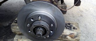
Removal and disassembly of service brakes
Place the car on level ground, place a jack under the axle and lift it. Further:
- remove the wheel and then the hub cover;
- unscrew the fasteners holding the inflation hose;
- pull out the axle shaft;
- use pliers to bend the washer and unscrew the nut;
- remove the hub along with the brake drum and the bearing located inside;
- pull out the tension spring located on the brake pads and the brackets (these elements must be cleaned of dirt).
Then you will have to unscrew the pipelines along with the bolts to remove the working cylinder. Next, you need to dismantle the shield along with the felt gland. Remove the brake valve, air booster, compressor, which are easy to disassemble. There is a caveat: when disassembling the master cylinder, do not remove the plug. One more point: it is also better not to touch the compressor GC (except in case of emergency). The valve seats are pressed out after removing the valve guides using narrow nose pliers.
Inspection and checking of parts
After rinsing the brake linings in gasoline, they need to be dried and treated with fine-grained sandpaper (a wire brush will also work). These parts are replaced if the distance to the top of the rivets is less than 0.5 mm. To process the fist together with the block, you need to place a plate 0.98-1 mm thick between them. Drum grooving is required if the groove depth is more than 1 mm.
Working cylinders
They are subjected to honing if they have traces of rust and mechanical damage in the form of scratches. Inspect the pistons and cuffs: if there is severe wear, replace the parts. Cracks, through tears, and ruptures are not allowed on the rubber boot of the cylinder. To replace the caps you will need a special tool.
Master brake cylinder
Inspect its mirror: nicks and scratches are not allowed - the element will have to be replaced. If there are traces of rust, the cylinder can be honed. When installing later, use new cuffs. Take a look at the piston: you need to install a new one if the wear on the brake system parts is too great. The cuffs are changed if they show signs of swelling.
Pneumatic system
| Name of service | Price |
| Replacement of a four-circuit pneumatic brake valve | 3700-6000r |
| Repair of pneumatic brake valve bulkhead | 2500-5000rub |
| Adjusting the brake force pneumatic valve | 4000rub |
Most often, any malfunctions occur due to natural wear and tear of materials, primarily rubber gaskets, rings, cuffs, covers (“caps”). They crack and tear, causing dirt to get inside, which leads to severe wear of metal parts. The pressure in the system drops, the pistons move unevenly, and they may jam.
The taps are located in different locations on different truck models. On some cars they are located below, on others - in front under the hood. In most cases, replacing parts requires dismantling the device. To remove the device from the car, you need to disconnect all the tubes suitable for it, unscrew several bolts that secure it to the frame or bracket. When disassembling, it is not necessary to disassemble completely. If the electronic part is working properly, then you don’t have to touch it. A repair kit is required to replace defective parts.