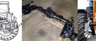
Rear axles of the same design were installed on passenger-and-freight vehicles of the UAZ-452 family and their modifications. The rear axle structure can be divided into crankcase, final drive, differential and axle shafts.
Main characteristics of the rear axle of the UAZ-452.
— Number of teeth of the main gears: drive — 8 driven — 41 — Roller bearing dimensions, mm: front double bevel, drive gear — 80x35x57 bevel, differential — 90x50x25 rear roller bearing with cylindrical rollers, drive gear shank — 52x20x15 — Main gear drive gear oil seal size , mm: 68x42X15 — Thickness of the shims included in the package installed between the end of the crankcase and the cover of the double tapered bearing, mm: 0.3, 0.5 — Thickness of the adjusting shims in the package installed between the inner rings of the double tapered bearing, mm: 0.1, 0.15, 0.25 — Thickness of the gasket installed in the crankcase connector with the cover, mm: 0.12 - Volume of oil poured into the crankcase to the level of the lower edge of the oil filler hole, l: 0.75 - Weight of the rear axle without wheels, kg: 98
Carter and axle housings for the rear axle of the UAZ-452.
The rear axle housing is split in the vertical plane. It consists of two parts connected by bolts and nuts with spring washers. A gasket is installed in the connector of both parts. An axle shaft casing is pressed into each half of the crankcase and additionally secured with electric rivets.
Flanges are butt welded to the casings, onto the ground necks of which oil seal rings are pressed and wheel hub bearings are installed. The bearings are secured with nuts and locknuts. The threaded ends of the flanges have rectangular grooves for locking the washer and lock washer of the wheel bearing nuts.
Both flanges have six threaded holes for the brake shield bolts. To prevent the pressure of the rear axle from increasing when it heats up during operation, a breather is installed on the left axle housing, connecting the internal cavity of the crankcase to the atmosphere.
Main gear of the rear axle of UAZ-452.
The final drive of the rear axle consists of one pair of bevel gears with a spiral tooth. The drive gear ring gear is manufactured as one piece with the shaft, which is placed between the front double bevel bearing and the rear cylindrical roller bearing. The rear bearing is pressed onto the end of the drive gear, the end of which is pierced in four places.
In this regard, when disassembling the rear axle, you must first separate the halves of the crankcase and remove the differential with the driven gear assembly. Then remove the drive gear and bearing assembly. When assembling bridges, all operations must be done in reverse order. If this order is not followed, failure of the rear bearing with cylindrical rollers is inevitable.
The outer ring of the rear roller bearing is installed in the holes of the axle housing support seat. The front dual bevel bearing is mounted on the front end of the pinion gear. The inner ring of the bearing, located at the ring gear, is pressed onto the smooth journal of the gear. The inner ring of the other bearing is mounted on the gear journal with a guaranteed small gap, which makes it possible to easily remove the bearing during adjustment, and also allows for reliable tightening of the inner rings.
The outer ring of the double tapered bearing, which has two raceways, is pressed into the front of the crankcase until it stops. A ring is installed between the end of the outer ring of the double tapered bearing and the crankcase to regulate the correct position of the drive gear. The thickness of the adjusting ring can be 1.28; 1.33; 1.38; 1.43; 1.48; 1.53 mm.
On the outside, this ring is secured with a cover, which is secured to the crankcase with six bolts and spring washers. A drive gear oil seal is installed in this cover to prevent transmission oil from leaking out of the axle housing.
Between the ends of the crankcase and the bearing cap there is a package of cardboard sealing gaskets, the thickness of which is selected 1.3 times greater than the actual distance between these ends. Between the inner ring of the double tapered bearing and the propeller shaft mounting flange on the drive gear there is an oil sump ring having a helical groove with a left-hand thread.
The parts installed on the drive gear are tightened with a nut. The tightened nut is secured with a cotter pin. A flange connects the drive gear to the rear end of the rear driveshaft. A stamped reflector is spot welded to this flange, which protects the oil seal from dirt and damage. Between the inner rings of the double tapered bearing there is a spacer ring and shims that regulate the tightening of this bearing.
The driven gear of the main gear is attached to the gearbox with ten bolts using a flange with a centering hole, ensuring its reliable and correct fit on the gearbox. There are ten evenly spaced bolt holes in the driven gear flange.
Each hole is provided with an eccentrically located cylindrical recess to accommodate the bolt head and prevent it from turning when the nut is tightened. The driven gear mounting bolt is cold-formed from chromium steel and heat-treated. A nut with slots is screwed onto the threaded part of the bolt and secured with a cotter pin.
To ensure lubrication of the double tapered bearing, an upper oil inlet hole and a lower oil outlet hole are drilled in the crankcase neck. The oil supply hole is located opposite the driven gear.
When the gear rotates, the oil entrained by it is pumped into the oil supply hole, through which it is supplied to the groove on the outer ring of the bearing, and then through the holes located between the raceways of this ring, it enters the cavity between the inner rings of the bearing and fills it, thereby ensuring its normal operation. work. Oil flows into the crankcase through the grooves in the gasket pack and in the bearing cap, and then through the oil drain hole.
Rear axle differential of UAZ-452.
The differential consists of four satellites, two semi-axial gears, a gear box, two thrust washers of semi-axial gears and two axles of the satellites. On the axes of the satellites in their middle part there are grooves with which the axes fit into one another, thus forming a detachable cross. The ends of the axles are rigidly fixed in the holes of the satellite box.
The satellite teeth are in constant mesh with both semi-axial gears, which are installed freely in the holes of the satellite box. The axle shaft gears are connected to the axle shafts using splines. To ensure better running-in, the satellite axes and satellites are phosphated. For the same purpose, the support washers of the semi-axial gears are coated with a thin layer of copper.
The satellite box is detachable and consists of two halves cast from malleable cast iron and connected with studs and nuts. From turning, the nuts are secured in pairs with lock washers whose tendrils are bent at the edge of the nuts. There are grooves on both halves of the gearbox for oil to enter the internal cavity to lubricate all rubbing surfaces of the differential parts. The gearbox rotates on two tapered roller bearings installed in the crankcase and crankcase cover.
The holes for the satellite axes in both halves of the satellite box are processed as an assembly. Therefore, a serial number is placed on both halves. When assembling the differential, the serial number of both halves must be the same.
The preload of the differential roller bearings is adjusted by spacers located between the ends of the gearbox and the inner rings of the differential bearings. The same gaskets regulate the position of the driven gear of the main gear, that is, the amount of lateral clearance, as well as the size and location of the contact patch.
Axle shafts of the rear axle of UAZ-452.
The rear axle axle shafts are of a fully unloaded type; they transmit only torque. One splined end of the axle shaft is connected to the side gear; at the other end there is a flange, which is rigidly connected to the rear wheel hub with six studs and nuts with spring washers. The axle shaft flange is centered relative to the hub using a collar.
Maintenance of the rear axle of UAZ-452.
Maintenance of the UAZ-452 rear axle during operation consists of maintaining the required level and timely changing of transmission oil, checking seals, timely detection of axial clearances in the final drive gears, periodically cleaning the breather, as well as tightening all fasteners.
The oil level in the axle housing must be no lower than the lower edge of the oil filler hole. When replacing, the oil is drained through the oil drain hole located at the bottom of the crankcase. If the oil is heavily contaminated or metal particles are found in it, the crankcase should be flushed with kerosene before adding fresh oil.
To flush the rear axle, you need to pour 1-1.5 liters of kerosene into the crankcase, lift the wheels, start the engine, engage the gear and let the engine run for 2-3 minutes, then immediately drain the kerosene and add fresh oil. With timely and proper care, the service life of the rear axle increases.
This is interesting: Extending the life of wipers
How to assemble a UAZ rear axle
Assemble the differential in the following order:
1. Before assembling the differential, lubricate the axle gears, satellites, thrust washers and satellite axles with transmission oil
2. Install thrust washers on the journals of the axle gears.
3. Install the axle gear with thrust washer assembly into the left gear box.
4. Install the satellites on the axis of the split cross.
Rice. 7. Pressing out the outer ring of the differential bearing
5. Install the detachable crosspiece (Fig. 1) with satellites into the left satellite box.
Rice. 8. Installation of satellite boxes according to marks
6. Install the axle gear with thrust washer assembly into the right gear box.
Holding the axle shaft gear, install the right satellite cup onto the left one so that the marks (Fig. 2) (serial numbers) of both cups are aligned.
7. Connect the halves with bolts and tighten them. Tightening torque 32–40 Nm (3.2–4.0 kgf).
Rice. 20. Rear axle
8. Install the main drive driven gear onto the gearbox, aligning the bolt holes. Install the bolts and tighten them.
Tightening torque 98–137 N m (10–14 kgf m).
For the assembled differential, the axle gears must be rotated using a splined mandrel from a force of no more than 59 N (6 kgf) applied over a radius of 80 mm.
Adjust the differential bearings (if they are replaced) in the following order:
Rice. 9. Pre-pressing of the inner rings of the differential bearings
1. Press the inner rings of the bearings (Fig. 9) of the differential onto the journals of the assembled differential so that there is a gap of 3.5–4.0 mm between the ends of the gearbox and the ends of the inner rings of the bearings.
Rice. 10. Rolling in differential bearing rollers
The main gear consists of a pair of bevel gears with a spiral tooth. The gear ratio of the main pair is 5.125:1 (41 and 8 teeth).
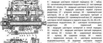
Rice. 1. Rear axle: 1 — rear axle housing cover; 2 - axle shaft; 3 — breather; 4 — axle shaft casing; 5 — differential bearing; 6 — adjusting shims for differential bearings; 7—differential box; 8 — roller bearing of the drive gear; 9— driven gear; 10 — adjusting ring for the position of the drive gear; 11 — bearing cover; 12 - oil removal ring; 13 — drive gear shaft flange; 14—tightening screw for the drive gear shaft; 15 — oil seal; 16 — gasket; 17 — double-row tapered roller bearing; 18 — spacer ring; 19 — adjusting shims for the drive gear shaft bearings; 20 - drive gear; 21 — satellite support washer; 22 — satellite; 23 — rear axle housing; 24 — support washer of the semi-axial gear; 25 — satellite axis; 26—pin; 27 — crankcase gasket; 28 - gear
The axis of the drive gear is shifted to the right from the longitudinal axis of the car by 75 mm.
The drive gear is mounted on two supports: a double-row angular contact roller bearing and a radial roller bearing 8 of a non-separable design. This bearing is pressed onto the rear end of the drive gear shaft.
The bevel differential with four satellites has a split box consisting of two halves connected by studs and nuts. The differential is mounted on two tapered roller bearings located in the crankcase and rear axle cover.
The driven gear is attached to the differential box flange with ten bolts. The satellites are installed on two axes, the relative position of which is fixed by grooves in the middle of the axes.
The satellites and semi-axial gears are equipped with replaceable support washers.
The axle shaft has a flange, which is installed on six wheel hub studs and secured with nuts.
The splined end of the axle shaft fits into the side gear.
To ensure reliable lubrication of the front bearing of the drive gear, the rear axle housing has channels in the casting through which lubricant is supplied by splashing when the driven gear rotates. The direction of the drain holes in the cover and crankcase ensures that the lubricant level is maintained at a constant level.
The rear drive gear bearing, differential bearings, and the ends of the side gears and pinions are lubricated by splash lubrication when the differential rotates in an oil bath.
In order to increase the reliability and durability of the front and rear axles, since March 1967, a crankcase with an oil supply channel A has been installed on them, into which oil is supplied from the drive gear of the main gear. From the channel, oil flows onto the differential bearing and ensures good lubrication. The interchangeability of components and parts has been preserved.
To eliminate the increased pressure that occurs inside the crankcase when it heats up during operation, a breather is installed on the crankcase casing.
Maintenance
During the first maintenance (TO-1), it is necessary to inspect the rear axle housing. If traces of grease are found on it, check the oil level and eliminate the problem.
Using TO-1, check: — fastening of the axle shaft flanges; - the oil level in the crankcase and add it, if necessary, to the lower edge of the filler hole.
During the second maintenance (TO-2) it is necessary:
check the tightness and condition of the crankcase by inspection; change the oil in the crankcase. If the oil is heavily contaminated, the crankcase should be flushed with kerosene before adding fresh oil. To flush, you need to pour 1-1.5 liters of kerosene into the crankcase, jack up the rear axle so that the tires do not touch the ground, start the engine and let it run for 2-3 minutes, then drain the kerosene and add fresh oil. If after long-term operation metal particles appear in the oil, then the bridge should be opened, inspected and, if necessary, replaced worn parts.
When filling the axle with oil, you should not turn the gears, as the oil will stick to them and enter the crankcase in greater quantities than required; — tighten the flange mounting nuts on the drive gear of the bridge; — check and correct by adjustment the play in the double tapered bearing of the drive gear. The adjustment procedure is indicated at the end of the section; — clean dirt and blow out the breather; — check the fastening of the crankcase at the connector and the fastening of the drive gear bearing cover.
Removing and disassembling the rear axle
For repairs, the rear axle is removed from the vehicle and disassembled. Disassembled parts are washed and inspected.
It is necessary to check the condition (wear) of bearings, oil seals, gear teeth, spline joints and other parts.
Defective or worn parts and seals are replaced with new ones.
The drive and driven gears of the main gear are not depersonalized when disassembling the rear axle. If necessary, the gears are replaced as a set, since at the factory they are selected in pairs based on contact, side clearance and noise and branded with the same number.
To remove the rear axle, you need to disconnect the flexible hose from the tee of the hydraulic brake pipeline installed on the frame cross member above the rear axle, the shock absorber struts, the driveshaft, the springs and roll back the rear axle.
To disassemble the rear axle, first remove the wheels, brake drums and axle shafts from it. To remove the axle shaft, you need to unscrew the nuts of the studs securing the axle shaft flange, tighten the two bolts installed on the flange, and remove the axle shaft.
Having straightened the bent edges of the lock washer, unscrew the nuts securing the wheel hub bearings, remove the hubs, rear brake shields and the pipeline.
The rear axle should be disassembled in the order shown below.
Unscrew the eight bolts (six of them with a special head) securing the cover to the rear axle housing, remove the cover, gasket and carefully remove the differential.
Remove the flange from the rear axle drive gear.
Remove the rear axle drive gear bearing cap, shims, gasket, slinger, bearing inner race and spacer.
Using a puller, press the drive gear together with the bearing out of the rear axle housing and remove the outer race of the bearing.
Using a tool, press out the inner ring of the drive gear bearing.
Sequence of disassembling the differential a. Using a puller, press out the inner ring of the differential bearings.
Remove the rear axle driven gear.
Having bent the antennae of the lock washers, unscrew the nuts and separate the halves of the satellite box.
Remove the support washers, satellites, side gears and axles.
The differential must be assembled in the reverse order of disassembly.
Before assembly, check the thickness of the support washers and replace them with new ones if the thickness of the axle gear washer is less than 1.2 mm and the satellite washer is less than 0.4 mm.
When installing support washers in the differential, the gap between the washer and the axle gear should be in the range of 0.05-0.45 mm (check with a feeler gauge).
rear axle block
The rear axle is assembled in the reverse order of disassembly, taking into account the following.
The double-row tapered drive gear bearing and tapered differential bearings are assembled with preload, i.e., with a preliminary axial load, which eliminates play in the bearings and reduces the harmful effects of shock loads. Adjustment procedures are listed at the end of this section.
After pressing the rear bearing onto the end of the drive gear shaft, its end is cored.
When assembling the axle, first install the drive gear with the bearing assembly, and then the differential with the driven gear.
When assembling the rear axle, the bearings and gears of the main drive must be adjusted in the following sequence: - adjust the preload of the double tapered bearing of the drive gear shaft and the differential tapered bearings; — adjust the side clearance and correct contact in the meshing of the main gears.
The adjustment operations are specified in the “Rear Axle Adjustment” section.
Before putting it in place, lubricate the working surface of the rubber seals with a thin layer of lubricant 1-13 (grease).
To ensure high tightness, it is recommended to lubricate the sockets of parts into which oil seals with a metal body are pressed with a thin layer of paint or paste, immediately before pressing the oil seals.
To press the oil seals into the socket, use a mandrel whose outer diameter is slightly smaller than the outer diameter of the oil seal.
The outer rings of the differential bearings are pressed into the housings of the crankcase and crankcase cover until they stop, and the inner rings of the bearings are pressed into the ends of the journal of the differential box until they stop.
When installing new gears of the main pair, adjust the lateral clearance and contact in mesh.
The oil-removing ring of the rear axle drive gear oil seal, installed between the flange and the inner ring of the bearing, has grooves at the end with a left-hand direction of rotation and is not marked. It must be borne in mind that the oil removal ring installed in the front axle has grooves with a right-hand direction of rotation and the marking “P”. Oil removal rings must not be swapped, otherwise oil may leak from the oil seal.
When installing the drive gear bearing cover (part 20-2402051-G) on the axle housing, you need to align the lubrication holes in the gasket and cover with the hole in the housing.
It is necessary to tighten the nut securing the flange on the drive gear fully. To align the slot on the nut with the hole for the cotter pin, unscrewing the nut is not allowed.
Before assembly, check and, if necessary, replace the drive gear oil seal and the axle housing gasket.
Cardboard spacers with a thickness of 0.3 and 0.5 mm are installed under the drive gear cover. Their thickness is selected after adjusting the main gear engagement and measuring the gap between the end of the crankcase neck and the cover. The thickness of the gaskets should be 0.2-0.4 mm greater than the gap size.
After assembly, the rear axle is checked on a stand under load and without it. A properly assembled rear axle must meet the following requirements.
During the test, there should be no increased noise or heating.
There should be no oil leakage through the cover seal and bolted connections.
Rear axle adjustment
The rear axle bearings, lateral clearance and contact in the meshing of the main gears are adjusted at the factory and during operation they remain unchanged for a long time. Therefore, they are adjusted only when parts are replaced or when there is significant wear on the rear axle bearings (when noticeable axial play of the driving or driven gear appears).
In the rear axle the following is adjusted: - preload of the double tapered bearing of the drive gear; — preload of tapered differential bearings; — lateral clearance and contact in the meshing of the main gears (only when installing new gears).
Adjusting the preload of the Double Tapered Pinion Shaft Bearing. When tightening the flange nut on the drive gear shaft of the rear axle during TO-2, the presence of axial play in the drive gear bearings is detected.
The gap is checked using a device with an indicator. If, during longitudinal movement of the drive gear shaft from one extreme position to another, the axial clearance in the bearings is more than 0.05 mm, it is necessary to tighten the bearings.
If there is no indicator device, check for clearance by moving the drive gear shaft by the flange by hand.
The bearings are tightened by changing the overall thickness of the shims between the bearing inner ring and the spacer ring.
The thickness of the adjusting shims is 0.1; 0.15 and 0.25 mm. With enough experience, the pinion shaft bearings can be tightened without disassembling the rear axle.
Rice. 2. Checking the axial clearance in the main gear drive shaft bearings
Rice. 3. Checking the tightness of the pinion shaft bearings
To do this you need to: - unscrew the nut and remove the flange from the drive gear shaft; - Unscrew the fastening bolts and remove the bearing cover together with the oil seal, oil ring, inner ring of the bearing, spacer ring; — remove the adjusting shim; — install all other removed parts in place and tighten the flange nut. When tightening the nut, you need to turn the drive gear by the flange so that the rollers take the correct position in the bearing rings. Check the quality of the adjustment.
If the gap is not eliminated, repeat the adjustment.
With the correct selection of the thickness of the gaskets, there should be no axial movement at the drive gear shaft, and the gear itself should rotate by hand without much effort.
If you have insufficient experience, you can adjust the axial clearance as follows.
Having disconnected one of the springs, the shock absorber and the hydraulic brake pipeline from the bridge, unscrew the bolts securing the cover to the bridge housing, move the cover and housing apart so as to disengage the drive and driven gears.
Unscrew the nut and remove the flange. Unscrew the bolts and remove the cover along with the oil seal, oil seal ring, inner bearing ring and spacer ring.
Remove the adjusting shim.
Reinstall the spacer ring, bearing inner race, oil removal ring, flange and tighten the flange nut. When tightening, turn the gear by the flange.
Using a spring dynamometer, check the amount of bearing preload with the cover and seal removed.
With proper adjustment, the dynamometer should show a force of 1.5-3.0 kg when installing the dynamometer hook into the flange hole (at the 40 mm arm).
If the dynamometer readings do not correspond to the specified values, repeat the adjustment, changing the thickness of the removed shims.
After completing the adjustment, replace the cover. In this case, it is necessary to align the lubrication holes in the crankcase, gasket and cover.
Tighten the nut on the splined end of the drive gear fully. To align the slot on the nut with the hole for the cotter pin, do not unscrew the nut back, but only tighten it. If the nut is not tightened sufficiently, the inner rings of the double-row roller bearing may rotate on the drive gear shaft, wear out of the gaskets, and dangerous axial play of the drive gear shaft may occur.
After adjustment, check the heating of the bearing during operation. Heating of the crankcase neck to a temperature of 80 °C or higher indicates that the bearing is overtightened and it is necessary to increase the thickness of the gaskets. A little heat is not dangerous.
Adjusting the preload of the tapered differential bearings. This tension is adjusted by selecting the number and thickness of shims installed between the ends of the inner rings of the bearings and the bearing journals of the differential box. The shims have a thickness of 0.1; 0.15; 0.25 and 0.5 mm. When adjusting, it is necessary to ensure that there is no lateral rolling and axial play of the driven gear; in this case, the gear should rotate in the bearings with little effort. The axial play of the driven gear is checked through the hole for the oil filler plug. An approximately equal number of shims should be installed under both ends of the differential.
If the bearings are too tight, you need to remove the adjusting shim from under the end of the differential on the side opposite the driven gear.
Adjusting the side clearance and proper contact in the mesh of the final drive gears. The specified adjustment is performed only when installing new final drive gears.
It is necessary to pay attention to the careful implementation of this adjustment, since incorrectly adjusted gears will operate with increased noise and wear out quickly.
Before adjusting the side play and proper contact in the gear mesh, it is necessary to adjust the preload in the pinion and differential shaft bearings as stated above.
After adjusting the preliminary load, adjust the lateral clearance in the mesh of the main gear gears of the assembled axle. This gap should be in the range of 0.2-0.6 mm when measured on the drive gear flange at a radius of 40 mm (check in four positions of the drive gear every revolution).
The position of the drive gear is adjusted by selecting the thickness of the adjusting ring installed between the flange of the crankcase neck and the outer ring of the double-row tapered bearing. Adjustment ring thickness 1.48; 1.53; 1.58; 1.63; 1.68; 1.73 mm.
The position of the driven gear is changed by moving the shims from one side of the differential box to the other. By rearranging the gaskets, the side clearance indicated above is achieved. The number of shims must not be reduced or increased as this will disrupt the preload in the differential bearings.
To measure the actual value of the lateral clearance in the teeth of the main gear gears, it is recommended to lock the driven gear (to eliminate the influence of the clearances in the differential and in the splines of the axle shafts).
After adjusting the side clearance, check the correct engagement using the contact patch on the teeth. To do this, the teeth of the driven gear are coated with a thin layer of paint and the drive gear is turned in both directions.
The amount of lateral clearance of the gears during these changes should not exceed the limits of 0.2-0.6 mm when measured at the shank of the drive gear at a radius of 40 mm.
Rear axle structure of UAZ 469
The device of this node
The Soviet SUV UAZ 469, produced by the Ulyanovsk Automobile Plant, is unique in its own way. The diagram of the rear axle of the machine is shown in Fig. 1. The design includes the following key components and assemblies:
- 1 — protective overlap;
- 2 — roller bearing of the differential device;
- 3, 8 — corrective auto-linings;
- 4 — tail part of the drive gear support;
- 5 — adjustment ring;
- 6 - oil removal holder;
- 7 - nut;
- 9 — front gear of the rear axle;
- 10 — head bearing support;
- 11 — hydraulic washer of the gear wheel axle shaft;
- 12 - gear element.
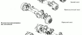
Arrangement and elimination of rear axle breakdowns
The rear axle is a support; inside it is the main transmission of the axle shaft, the differential. It can be of two categories: with a single main gear or an additional wheel drive. Wheel regulators, which increase torque and transmit it to the hubs of the conductive wheels, are located at the ends of the beam.
Wheel roller bearings rest on the regulator housings. Wheel gearboxes provide enormous ground clearance and are gears meshed internally. The main gear is bevel, with a spiral tooth, a bearing unit, which has a main gear and a bevel drive with 4 satellites. A satellite is a gear, compact, simple, rarely fails, and facilitates quick, easy gear changes.
The crankcase has a drain and fill hole and contains a certain amount of oil to lubricate the wheel hydraulic adjuster.
The rear converter support is detachable and consists of elements such as a cover, contamination protection, and pressed-in axle shaft housings. Its dimensions have been reduced, the gear ratio has been reduced to 2.77.
The driven rear axle gearbox is mounted on the shaft. It is installed in a roller bearing and bushing, tightened with a nut, and secured into the groove of the shaft. The ends of the gearbox shafts have movable couplings that help group and separate the shafts from the wheel hubs if necessary.
When the clutches are disconnected, the UAZ 469 becomes rear-wheel drive. This is useful on good paved roads. When driving in impassable terrain, turning off is not advisable. You can disconnect and connect the hubs from the start of operation of the quick response clutch or the hub cam. In this case, you do not need to crawl under the bottom of the car.
Differences between military bridges and civilian ones
Military and civilian bridges differ in that the former have not only a main gear, but also final wheel drives. The transfer case design of these cars is identical. The transmission of the UAZ 469 increases the torque received by each wheel, so a vehicle with a military axle has much better off-road and on-road characteristics.
A significant advantage of this system is that the axle of a military vehicle with side gears is 4 cm higher than that of a civilian vehicle. As a result, the vehicle's ground clearance is significantly improved when overcoming obstacles on the road. At the same time, military axles are manufactured with an overall gear ratio that is much higher than all other designs. This results in a significant increase in torque. A car with such characteristics is slightly inferior to its analogues in terms of speed characteristics.
An engine that constantly operates at high crankshaft speeds wears out its life much faster. The gear ratio of old civil bridges is 4.625 or 5.125. This depends on the number of teeth on the final drive sprocket.
For Military axles, the gear ratio is 5.38. The final drive ratio is 2.77 and the final drive ratio is 1.94. For Spicer axles, the gear ratio is 4.111. This is for carburetor cars. The gear ratio for diesel cars is 4.625.
On civilian UAZ 469 axles, a differential with forced or automatic locking is installed on each axle. The locking drive is used in different ways:
- pneumatic;
- Electricity;
- mechanical.
When installing a pneumatic drive, the car is retrofitted with a pneumatic system of the simplest design. In addition to blocking the UAZ 469 on civilian axles, it can solve many related problems.
Different bridges in the UAZ 469 differ in track width. Civilian and military axles were once produced in widths of 1443-1445 mm. Now the plant produces blocks up to 1600 mm wide. This is basically a modern Spicer design. The axial weight of the UAZ 469 collective farm is 120 kg, military 140 kg.
Construction of a military bridge (photo)
UAZ steering axle boot
Photo of an open side gearbox of a military UAZ axle
Image of a dismantled onboard gearbox of a UAZ car
Military bridge UAZ mushroom
Repair Gearbox UAZ 469
Assembling a pump for an IZH-Techno fire truck on a military axle
Dismantling the differential bearing of the UAZ military axle
Video replacement and adjustment of the main pair on the UAZ military bridge
Features of unit dismantling
When removing the rear axle, you need to unscrew the tail unit nut, remove the washer, mating flange, cover of the front gear roller assembly, and press the assembled gear with bearings out of the oil cooler at the rear of the car.
This circuit is excellent for disassembling a differential device. The next step is to unscrew the splines connecting the driven gear to the gearbox and reset it. Divide both parts of the box, pull out the gears, planetary gear rods, and support nuts. When assessing disassembly, pay attention to the integrity of the gear wheel teeth. If they are damaged, the part must be replaced. To remove rollers, outer and inner rings, special tools are required. Strictly study and understand the disassembly sequence so that you can accurately perform all steps in reverse order when reassembling.
When inspecting the oil stripper ring, check for surface irregularities. If yes, process to a thickness of 5 mm. The same goes for the cardan flange. Grinding height up to 53 mm. Wash the protective surfaces. Blow out the oil outlets. Drive design parts and axle shafts should be replaced if there are scuff marks or severe wear.
Nuances of installation and adjustment
The assembly (diagram) of the differential drive structure is carried out as follows.
- Connection of both satellite boxes depending on the case serial number.
- A crosspiece is inserted into the left satellite box.
- Place the assembled gear in the left box.
- Lubricate the differential units (axle gears, satellites, axles, thrust washers) with transmission oil.
- Secure the necks of the gear rings of the axle shafts with support washers.
- The satellites must be secured to the axis of the disconnected cross.
- Carry out the same actions with the right box.
- Tighten the parts of the boxes, insert the driven wheel of the base gear.
The foreman goes through the unit
Turn the six axle shafts of the mounted differential using splines with a force of no more than 59 N. Adjustment of the drive structural elements is carried out when replacing them.
- Secure the inner rings of the differential bearing units to the journals; the end play between the box and the rings should approach 3.5-4.0 mm.
- The installed differential differential is closed with an auto-gasket and a reservoir cap. Roll the bearings to establish the correct position. Secure the heat exchanger lock.
Adjusting the differential on a UAZ Patriot SUV
The device by which torque is divided between the wheels is called a differential. Thanks to its presence on the UAZ Patriot SUV, it is possible to change the rotation speed of each of the wheels. After all, when you turn the steering wheel, the outer wheel moves in a larger arc than the inner one and travels a greater distance. If differentials are not installed on the car, the wheels will slip when turning. This will lead to rapid tire wear, damage to the transmission, steering mechanism and accidents on the road. To eliminate this phenomenon, cars are equipped with a differential. Thanks to this element, it is possible to rotate the wheels at different angular speeds, which eliminates their actual slipping when turning. But today we will pay attention not to the design of the differential on the UAZ Patriot SUV, but to its adjustment. Why adjustment is needed and how it is carried out, let's take a closer look.
Forward and reverse torques
- Precise engagement in engagement with low load.
- Microcontact on top of the tooth (when debugging, move the head part towards the driven part).
- Contacting at the root of the clove (correction: the conductive one should move away from the driven one).
- Block contact is the narrow end of a tooth (deviation of elements from each other).
- Contact on the volumetric side of the tooth (deviation of the driven to the leading).
The gasket set is installed between the valve end of the front bearing assembly, the wheel and the axle support. The thickness of the package is a gap not exceeding 1.3.
Important parts of the unit
Secure the outer bearing lock assembly with the cuff with bolts, install the flange, and secure the washer with a cotter pin. A prefabricated differential is installed in the unit pan, then oil seals between the crankcase and the damper. The top of the pallet is mounted taking into account the spring pads located in the outer portion of the bridge.
The mounted bridge should not heat up while the machine is moving. Correctly adjusted parts will not cause heating. Of course, you just need to check that the driven gears are not jammed or caught, if the device has any.
Installation, adjustment, and repairs must be carried out on time. Safety when driving in a car depends on this. Maintenance of the UAZ bridge part is as follows.
- Constantly maintain the technical level, timely change the oil, check the seals, detect and eliminate axial gear play in the head drive of the unit. Systematically monitor the adhesion of fastening parts of components and assemblies.
- Pay great attention to cleaning the safety valve. If the oil is dirty or contains iron impurities, the heat exchanger should be flushed with kerosene before replacing it.
Experienced drivers recommend pouring 1 liter of gasoline into the pan, raising the wheels, connecting the engine, letting it run for 1-2 minutes, then draining the remaining gasoline, draining it, and pouring clean motor oil into the tank.
Steering
The steering of the UAZ 469 car is closely linked to the front drive axle, since the main components and parts are fixed to it. Steering equipment:
- Steering gear assembly with power steering.
- Cardan joint of the steering shaft.
- Steering bipod.
- Pump drive belt.
- Power steering pump with bracket, mount, bracket spacer, spacer corner.
- Oil tank with bracket and tank clamp.
- Oil filter.
- Fastening kits.
- Fan spacer with fasteners.
- Additional pulley with fasteners.
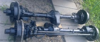
How the UAZ front axle works: detailed instructions for maintenance and repair
UAZ is a legendary SUV, popular both in Russia and beyond its borders. The car has been produced for quite a long time, which has proven the reliability of its design. This machine is actively used in the army. There are minor differences between the civilian and military versions. However, both here and there the UAZ front axle showed its best side. There are several modifications: on-board, regular, “loaf”, etc. Also, one cannot fail to note one of the advantages of the car - maintainability and the ability to restore the functionality of any unit, even in “garage” conditions. The mechanism allows you to activate all-wheel drive, which helps you confidently overcome obstacles.
Blocking test video
Related products:
Electrical locking connection kit for UAZ without automatic shutdown (vehicles with a mechanical speedometer)
Electric lock connection kit for UAZ with automatic shutdown (vehicles with electronic speedometer)
Sales are carried out from a warehouse in Ulyanovsk. Delivery of the product “Differential (cross-wheel) with electric locking UAZ Spicer/Timken bridges” is carried out to Moscow, Samara, St. Petersburg, Nizhny Novgorod, Yekaterinburg, Saratov, Krasnodar, Kazan, Perm, Orenburg, Penza and any other cities and regions of Russia.
UAZ front axle structure
It consists of a crankcase (sometimes called a stocking), a differential and a final drive. The rear and front axles have no fundamental differences. The only difference is in the direction of the thread of the oil rejection ring located in the main gear. The current design of the UAZ front axle is shown in the picture below. The support placed on the casing is fixed with five hardware. Pin bushings are pressed into the support. A pair of pins “engages” in holding the fist. He also holds the housing cover of the wheel gearboxes. A pin is fixed on it along with a shield on which there are parts of the brake system.
The pins do not rotate in the fist thanks to pin-type stoppers. The fist itself is made with preload (0.02-0.1 mm). The UAZ 469 axle is adjusted using spacers. Location: between the turn lever and the trim (left or right). The spacers are located between the pads and the fist.
One of the features of the described mechanism is that, in addition to increasing cross-country ability, it also turns the wheels. For this purpose, Birnfield ball joints are used. Their cavities contain lubricant that does not need to be replenished throughout their entire service life. The cams, as well as the axis of the pins, are inclined, which allows the wheels to be returned to the middle position after making a turn. The main advantages of the beam (Spicer):
- track is 1.6 m, which has a positive effect on the stability of the car;
- the wheels rotate at an angle of up to 32 degrees, which gives the machine improved maneuverability;
- instead of leaf springs, a dependent suspension on springs is mounted;
- no need to replace lubricant in mechanisms (fists);
- removable cover facilitates access to parts in case of repair;
- the differential together with the gearbox are in one housing - this increases rigidity and service life;
- An improved satellite gear has reduced noise.
Particularly worth mentioning are the hinges, or more precisely the stabilization of angular velocity. This is a design that ensures the stability of rotation of two shafts: the drive and the accompanying. The hinge includes two forks: in their sockets there are 4 balls. In the middle sectors of the parts there is a fifth one, needed for installation operations. In particular, centering the fork. To deactivate the front-wheel drive, there is a special device consisting of a clutch, bolts, and balls.
Distinctive features of the military version
The main feature of the front axle in the military version is the placement of the gearbox. It is located higher. The second distinctive point is the gear ratio - 5.38. The civilian version of UAZ 469, 452, 3151, 3303 has 4.6 or 5.125. All these characteristics increase the distance from the bottom of the car to the road surface from 220 to 300 mm. Those who want to quickly replace an ordinary bridge with a military one will be disappointed: this will not work without alterations. The reason is in the design of the bipod and suspension. In addition, driveshafts differ in length.
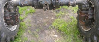
Carter
UAZ 469 vehicles are equipped at the manufacturer's factory with several options for front drive axles. Accordingly, the crankcases for each model of the drive unit will be different. The crankcase is the body of the bridge. Among motorists you can still hear its other name - stocking. Gears, shafts, and axle shafts are placed inside the crankcase, thanks to which rotational motion is transmitted from the engine to the wheels.
The UAZ 469 bridge of the Timken type, civil or collective farm, is split. The housing of such a bridge consists of two halves. Casings containing axle shafts are pressed into each of them. After completing the internal contents, the housing of such a bridge is assembled into a single whole. Safety valves are also installed on the casings. They limit the increase in pressure in the oil system.
There are pin assemblies at the edges of the crankcase casings. They consist of ball joints with steering axle housings or steering knuckles on them. Inside the ball joint housings, CV joints are installed - constant velocity joints. The outer hinge pins are located in the wheel hubs. CV joint UAZ 469 collective farm bridge price on Russian markets and portals ranges from 1,500 to 3,000 rubles.
Maintenance
Maintenance of the UAZ bridge is simple and comes down to monitoring the level of lubricant and topping it up and replacing it. The second point is to check the seals for leaks. It is regularly necessary to check the reliability of the fastenings, especially if the machine is used in difficult road conditions. Eliminate axial play in the differential bearings in a timely manner.
Assembly and connection diagram
When assembling the structure, do not remember several features:
- Press the bushing into the trunnion flush with the end of the washer socket. After completing the procedure, the sleeve must be deployed;
- Place one thrust washer inside the trunnion, the second - in the support. The oil lines in the thrust washers should face the joint. The washer is secured by punching in 3-4 places;
- When installing the hinge, add lubricant to the ball joint;
- Treat the pins and bushings with liquid lubricant.
To obtain the required axial tension, you need to select a certain number of spacers (but not less than five). They are installed on the ends of the knuckle body at the top and bottom. Their number should be the same. Soak the felt ring of the ball joint oil seal with engine oil. If possible, check the bridge on a bench after assembly. If the assembly is done correctly, the axle shafts should not heat up or make excessive noise when braking. Leaks through seals, cuffs, and bolted connections are not allowed.
How to disassemble a bridge
The first step is to remove the brake drum. Next, the hubs and hubs are dismantled. Along the way, inspect the bearings, which may have worn out and will have to buy new ones.
- Unscrew the brake system hose, it will get in the way, and remove the brake shield;
- Pull out the CV joint;
- Remove the rotating mechanism and shank;
- Divide the stocking into two parts;
- Remove the pair from one part of the bridge and the other.
Rear hub adjustment
We begin adjusting the rear hub with diagnostics.
We jack up the rear axle, then spin the rear wheels in different directions. The wheel should spin freely without jamming or extraneous noise. We spin different wheels and compare the sound. If there are any differences on one, it will be immediately clear. If there are no problems with wheel rotation, then check the wheels for play. To do this, take the wheel and swing it in different planes. If there is even the slightest hint of play, we move on to the next stage.
Disassembly
It may well be that if a small play is detected when removing the axle shaft, the play may turn out to be quite large. The axle shaft connected to the hub gives great leverage. Next, using a large Phillips screwdriver, remove the cap, which is secured with two bolts. We dismantle the axle shaft; to do this, unscrew the bolts with a 14mm head.
If the axle shaft does not come out immediately, there are special bolts in the flange that we screw in so that the axle shaft comes out. After removing the axle shaft, the play becomes quite noticeable. We remove excess grease so that we can clearly see the edges of the nuts and the petals of the keyholes. We begin to bend the petals of the keyholes that secure the nuts. There are two nuts, one is a locknut, the other is an adjusting nut. Unscrew the fixing nut with a hub wrench. Remove the lock washer.
Adjustment options
The adjustment consists of rotating the adjusting nut to catch the moment when there is no longer any play, but the wheel rotates freely.
The official instructions describe in detail how to adjust the hub, define the tightening torques and the procedure.
- Rotating the wheel as the car moves, smoothly tighten the adjusting nut; as soon as we feel the slightest slowdown of the wheel, we immediately stop tightening the nut. We check the backlash, if it is gone, the goal has been achieved.
After adjustment, we try to squeeze more lithol into the free cavities.
Then we put the lock washer in place, preferably a new one. Tighten the control nut and unbend the washer blades. If necessary, change the axle flange gasket. We tighten everything, check the gaps. If everything is fine, we continue to operate the car with pleasure. Have a good trip.
Repair of the most common faults
Restoring the bridge to operability is not very difficult: but it is required to be careful when performing operations. What “diseases” are most common?
Leak formation
Where the steering knuckle connects to the bridge, there is an oil seal - one of the weak points of the design in terms of lubricant leakage. The oil seal can leak oil not only due to wear, but also when the breather is clogged. If you add more lubricant than required, the result will be the same: a leak. There are two types of oil seals:
- rubber: inexpensive, but also short-lived;
- polyurethane: more expensive, have a long service life.
To replace a part, place the car on a level place and jack up the problem side, loosening the wheel nuts in advance. Further:
- remove the steering knuckle;
- clamp the part in a vice;
- pull out the oil seal by prying it with a flat screwdriver or other suitable tool;
- pull the oil seal out of the support cavity;
- Lubricate the seal before installation;
- press in the oil seal using a tube of the appropriate diameter.
- Installation is in the reverse order.
The mechanism began to hum
First of all, check the oil level. If it is normal, the bridge will have to be removed and disassembled. If the bridge hums constantly in any driving mode, the reasons may be as follows:
- incorrect setting or limiting service life of differential bearings;
- breakage (wear) of the axle shaft (its bearing);
- wear, damage, incorrect gear adjustment.
These bearings simply need to be replaced with new ones. If a humming noise appears during a sudden stop or acceleration, the reasons are as follows:
- incorrect clearance between the final drive gears;
- The final drive gear teeth do not mesh correctly.
In this case, you need to correctly adjust the gearing or replace defective parts. If the bridge hums when the UAZ enters a turn and moves in a straight line, the reasons may be the following:
- satellites rotate with great effort;
- abnormal operation of the axle gears in the differential;
- destruction, severe wear of the axle bearing;
- incorrect clearance between gears located in the differential.
To restore the functionality of the mechanism, adjust the clearances correctly and replace damaged, worn bearings. It is worth noting that the desired result when adjusting the gaps can only be achieved on a bench.
Wheel axial play
It occurs when the wheel bearings are incorrectly adjusted or when they completely fail, which is caused by over-tightening. As a result, the bearings become very hot, the smear liquefies and flows out. Algorithm of actions when performing the correct adjustment:
- Jack up the wheel on the desired side;
- Use a puller to remove the axle shaft;
- Move the lock washer to the side and unscrew the lock nut;
- Spin the wheel: if it rotates tightly, the reason may lie in jamming of the cuffs, contact of the drum and pads, etc.;
- Tighten the adjusting nut. Do this gradually while spinning the wheel. Use the WRENCH;
- Unscrew the nut about a third of a turn and install the lock washer. Tighten the nut and lock it;
- Check how the wheel rotates: it should spin freely without sticking;
- Replace the axle shaft, replace the bolts and tighten them.
You can finally check while moving. If the hub gets very hot, loosen the hub nut about 1/6 of a turn.
Design features of the product
Structurally, the rear axle of the UAZ Patriot SUV has the following form:
The Spicer Bridge consists of the following main parts:
- differential;
- two axle shafts;
- main couple.
The internal structure of the rear axle, or rather its gearbox, has the following form, shown in the diagram below.
All these parts are located in the bridge structure. The crankcase cover 35 together with the gasket 42 ensures the tightness of the internal structure of this design. Inside the device is filled with lubricant – oil. The rotation of gears and the friction of bearings requires careful treatment, which is ensured thanks to the lubricant. The owner of the SUV can only monitor the oil level in the axle, which can decrease due to deterioration of tightness. The design of the UAZ-3163 gearbox is not particularly difficult and allows you to repair the product at home.
Malfunctions and ways to eliminate them
If the gearbox fails, the vehicle cannot be used and appropriate repairs are required. Driving a car with the front axle connected is allowed only if it overcomes any obstacles, and driving on an asphalt road requires disabling it using the installed hub couplings.
The absence of a cross-axle differential leads to increased wear and tear on the rear-wheel drive unit, which is why in frequent cases, owners of UAZ-3160 and 3163 resort to independent modernization of the vehicle.
There are the following types of malfunctions of the Spicer rear axle on the UAZ Patriot SUV and methods for eliminating them.
- Detection of oil leaks that fill the device, as a result of which minor repairs are required to replace the seals or gaskets.
- The gearbox produces excessive noise and knocking, which leads to the need for repairs. In this case, extraneous noise can be produced due to wear of the bearings or the absence of oil in the bridge tank. Lubrication can eliminate these types of problems.
- Noises and knocking noises when cornering are caused by wear of the teeth of the satellites or semi-axial gears, which requires adjustment of the gap or replacement of defective parts.
In fact, the rear axle gearbox has many more faults, which can often be detected only after opening the crankcase cover. In frequent cases, the crankcase cover is deformed due to impacts with an obstacle when driving off-road. In this case, the integrity of the cover is compromised, which leads to the penetration of various third-party substances, such as dust and water, into the device, or more precisely, into the gearbox. In this case, these negative third-party substances cause many malfunctions: from oil leakage to jamming of the gearbox gears. Many owners, when operating a vehicle in harsh off-road conditions, resort to replacing the standard crankcase cover with a special reinforced one. The reinforced lid is made of cast iron and bronze alloys. In this case, the strength of the axle housing cover increases tens of times. The reinforced crankcase cover covering the gearbox has the following appearance.
The cost of such a device is about 5 thousand rubles, which not every full-time driver can afford. To replace the cover, you need to drain the oil and replace the standard part with a reinforced one, not forgetting to replace the gasket.
Often, knocking in the bridge structure is the main factor in the occurrence of failure, and indicates that the product requires repair. If a knocking noise appears in the axle, it is prohibited to operate the vehicle until the cause of the noise is eliminated or qualified maintenance is carried out. If the knocking cannot be determined on your own, then it is better to entrust it to an experienced specialist who can fix the problem in a matter of minutes or hours.
In frequent cases, knocking indicates the following causes of malfunctions in the rear axle of a UAZ Patriot:
- The clearance between the main gears has been increased.
- Loosening rear suspension bolts.
- Increased clearance between drive gear and flange.
- A knock may also indicate that there is a malfunction of the driveshaft, in particular, play has appeared in the crosspiece.
If the UAZ Patriot SUV is driven on rough terrain, then a knocking sound in the axle after the next race should not cause much distress, since this is a normal phenomenon that requires the intervention of an experienced craftsman in the design of the gearbox.
Removal and installation of the Spicer rear axle is carried out in case of wear or damage to the integrity of the structure. But, as practice shows, the rear axle on the UAZ-3160 and 3163 lasts quite a long time, which cannot be said about the gearbox, although periodic maintenance of the axle gearbox also allows you to extend the service life of the product. Lubrication of rotating parts is especially important. Untimely replacement of lubricant or its absence leads to not very pleasant consequences, requiring repair work with a significant investment of capital. Therefore, in order to avoid such unpredictable troubles, you should periodically check the presence of lubrication and perform preventative maintenance on the entire structure of the unit.
At this stage, we can summarize and conclude that, like any rear-wheel drive car, the UAZ Patriot SUV needs timely care and troubleshooting, and only in this case will it be possible to prevent a serious malfunction on the road.
Source
Disassembling the steering knuckle without dismantling the bridge
To perform this operation, first disconnect the hub by unscrewing the 6 bolts. Then bend back the lock washer, unscrew the hub nuts and remove it with the wheel and drum. Further:
- disconnect the oil deflector by unscrewing 6 bolts;
- remove a couple of bolts on the steering knuckle, hang the brake shield on the spring;
- remove 6 bolts to disconnect the cover and the knuckle body;
- to remove it, unscrew the bolts and remove the o-rings;
- Unscrew the knuckle linings, remove the kingpins and remove the steering knuckle housing.
As you can see, it is quite possible to repair the front axle of a UAZ with your own hands. However, you need to have experience in carrying out such work and a good set of tools.
Rear axle structure of UAZ 469
The device of this node
The Soviet SUV UAZ 469, produced by the Ulyanovsk Automobile Plant, is unique in its own way. The diagram of the rear axle of the machine is shown in Fig. 1. The design includes the following key components and assemblies:
- 1 — protective overlap;
- 2 — roller bearing of the differential device;
- 3, 8 — corrective auto-linings;
- 4 — tail part of the drive gear support;
- 5 — adjustment ring;
- 6 - oil removal holder;
- 7 - nut;
- 9 — front gear of the rear axle;
- 10 — head bearing support;
- 11 — hydraulic washer of the gear wheel axle shaft;
- 12 - gear element.
Arrangement and elimination of rear axle breakdowns
The rear axle is a support; inside it is the main transmission of the axle shaft, the differential. It can be of two categories: with a single main gear or an additional wheel drive. Wheel regulators, which increase torque and transmit it to the hubs of the conductive wheels, are located at the ends of the beam.
Wheel roller bearings rest on the regulator housings. Wheel gearboxes provide enormous ground clearance and are gears meshed internally. The main gear is bevel, with a spiral tooth, a bearing unit, which has a main gear and a bevel drive with 4 satellites. A satellite is a gear, compact, simple, rarely fails, and facilitates quick, easy gear changes.
The crankcase has a drain and fill hole and contains a certain amount of oil to lubricate the wheel hydraulic adjuster.
The rear converter support is detachable and consists of elements such as a cover, contamination protection, and pressed-in axle shaft housings. Its dimensions have been reduced, the gear ratio has been reduced to 2.77.
The driven rear axle gearbox is mounted on the shaft. It is installed in a roller bearing and bushing, tightened with a nut, and secured into the groove of the shaft. The ends of the gearbox shafts have movable couplings that help group and separate the shafts from the wheel hubs if necessary.
When the clutches are disconnected, the UAZ 469 becomes rear-wheel drive. This is useful on good paved roads. When driving in impassable terrain, turning off is not advisable. You can disconnect and connect the hubs from the start of operation of the quick response clutch or the hub cam. In this case, you do not need to crawl under the bottom of the car.
How to connect
To turn on the front axle on the UAZ “Bukhanka”, follow these steps:
- Turn the couplings connecting the wheel hub to the axle shaft.
- Use the transfer lever, which is installed in the cab, to engage front-wheel drive.
The clutches located on each wheel are engaged/disengaged by adjusting the rotary hubcaps. Most often, there are marks on the caps that indicate the current position of the clutches - 4 x 4 / 4 x 2. On relatively new axles, you can manually switch the clutches to 4 x 4 mode by simply removing the drive axle hub cover. There is no need to crawl under the car.
After the clutches on the front wheels are switched to 4 x 4 mode, you can engage all-wheel drive: first set the transfer lever to the neutral position, and then move it to the extreme forward position.
Front-wheel drive is activated both when the car is stationary and when the car is moving (speed should be less than 40 km/h). Disabling all-wheel drive is done in the following sequence:
- stop the car;
- turn off the front axle using the transfer lever;
- Set the coupling rotary caps to the 4 x 2 position.
Important! You cannot connect the front axle only from the passenger compartment if the clutches on the wheels are disconnected.
Although driving with all-wheel drive is fun, it is very expensive: high fuel consumption, rapid wear of the front axle components and tires. Therefore, on a UAZ it is better to use the 4 x 4 mode only on problem sections of the road, and turn it off in the city or on good road surfaces.
Features of unit dismantling
When removing the rear axle, you need to unscrew the tail unit nut, remove the washer, mating flange, cover of the front gear roller assembly, and press the assembled gear with bearings out of the oil cooler at the rear of the car.
This circuit is excellent for disassembling a differential device. The next step is to unscrew the splines connecting the driven gear to the gearbox and reset it. Divide both parts of the box, pull out the gears, planetary gear rods, and support nuts. When assessing disassembly, pay attention to the integrity of the gear wheel teeth. If they are damaged, the part must be replaced. To remove rollers, outer and inner rings, special tools are required. Strictly study and understand the disassembly sequence so that you can accurately perform all steps in reverse order when reassembling.
When inspecting the oil stripper ring, check for surface irregularities. If yes, process to a thickness of 5 mm. The same goes for the cardan flange. Grinding height up to 53 mm. Wash the protective surfaces. Blow out the oil outlets. Drive design parts and axle shafts should be replaced if there are scuff marks or severe wear.
Nuances of installation and adjustment
The assembly (diagram) of the differential drive structure is carried out as follows.
- Connection of both satellite boxes depending on the case serial number.
- A crosspiece is inserted into the left satellite box.
- Place the assembled gear in the left box.
- Lubricate the differential units (axle gears, satellites, axles, thrust washers) with transmission oil.
- Secure the necks of the gear rings of the axle shafts with support washers.
- The satellites must be secured to the axis of the disconnected cross.
- Carry out the same actions with the right box.
- Tighten the parts of the boxes, insert the driven wheel of the base gear.
The foreman goes through the unit
Turn the six axle shafts of the mounted differential using splines with a force of no more than 59 N. Adjustment of the drive structural elements is carried out when replacing them.
- Secure the inner rings of the differential bearing units to the journals; the end play between the box and the rings should approach 3.5-4.0 mm.
- The installed differential differential is closed with an auto-gasket and a reservoir cap. Roll the bearings to establish the correct position. Secure the heat exchanger lock.
Installation and adjustment of ball bearings of the conductive gear of the rear converter.
- Fixing the guide elements to the main gear.
- Grinding in the tail end with the guide element.
- Location of the spacer and spacers for the roller assembly between the inner rings.
- The main fastener for the main gear adjusting ring.
All intermediate actions, punching, are shown in the diagram in Fig. 2. This diagram describes all the nuances in more detail.
- When adjusting the head gear assembly, there should be no longitudinal play; the spring dynamometer will show the force. Indicators for new parts are 15-30 N, for run-in parts - 20-35 N. To reduce the tension when installing bearings, you can add spacers. To increase - remove.
- The adjustment has come to an end, we fix all the parts in their places and secure them with high-quality cotter pins.
The backlash adjustment and the location of the central gear gear are carried out as follows.
- A potential with adjusted prefabricated roller bearings is installed in the heat exchanger, their separation gasket is installed with a cover secured with a bolt.
- The distance between both teeth is set: 0.2-0.6 mm. The backlash is adjusted taking into account the number of driven gear oil seals: when their number decreases, the backlash must increase, and vice versa. When rearranging the gaskets, the tension of the potential elements will not be disrupted only when the number of gaskets does not change.
- The meshing diagram of gear wheels along the contact patch is shown in Fig. 3.
Return to contents