General characteristics
UAZ gearbox
A gearbox is a car's gearbox. The UAZ 469 has a manual 4-speed gearbox equipped with inertia-type synchronizers. They are designed to engage gears without noise or rumble. Synchronizers help equalize the speed of the connecting teeth before engaging. The rotation speeds of the motor and wheels do not match; a synchronizer is needed to combine them. In addition, the gearbox allows the car to move in reverse.
The UAZ 469 gearbox consists of the following parts:
- input shaft;
- front cover;
- special purpose nut;
- auxiliary fasteners;
- auto laying;
- ball bearings;
- secondary shaft drive bearing;
- crankcase;
- coupling for connecting III and IV gears;
- 3rd gear gear;
- 2nd gear gear;
- clutch for connecting 1st and 2nd gears;
- 1st gear gear;
- secondary shaft;
- fastening washer;
- gearbox spacer ring;
- mounting bolt;
- washer for fastening;
- intermediate shaft;
- reverse gear axis;
- reverse gear;
- cork;
- block of gear wheels driving the intermediate shaft and 3rd gear;
- lid.
The device of the UAZ box
If you are interested in the UAZ gearbox diagram, it is easy to find it in photos and drawings posted on various sites on the Internet.
4 studs are screwed into the clutch housing, on which the gearbox is attached. The intermediate shaft drive has gears that are in stable mesh. 1st gear gears have straight teeth, 2nd and 3rd gears have spiral teeth. They are mounted on the drive shaft, supported by needle bearings. The drive shaft has 2 supports. When engaging second gear, the role of the clutch is performed by the first gear. Activation of reverse and first gear occurs due to the movement of gears. Gearbox ball bearings. To prevent movement along the axis, the gears are secured with rear bearings. The rear bearing of the intermediate shaft is integrated with the shaft itself using a bolt.
The switching device has 3 forks attached to the rods with locking screws and located in the side cover. The ball-shaped stopper for neutral position and engaged gears has a rod. The locking blocks located between the rods do not allow connecting 2 gears at the same time. The support contains a lever that helps move the forks. It itself is pressed by a spring to the supporting spherical surface. The boot placed on the lever prevents water and dirt from entering the device. To prevent accidental engagement of reverse gear (the driver may simply get confused), this device contains a fuse - a plunger, which is equipped with a return spring and a ball.
The box lubrication device is combined with the transfer case. Lubricant from the transfer case passes into the UAZ gearbox through a double-row bearing (angular contact) and the existing drain device, after which it returns through the drain hole.
UAZ gearbox repair
The manual transmission is the most important transmission unit of the UAZ 469 vehicle . The UAZ 469 gearbox has a responsible and fundamental task - monitoring the variability of the amount of engine torque and carrying out transmission from the engine to the drive wheels of the vehicle. The UAZ 469 manual transmission has a fairly long service life. This does not mean that the gearbox does not need repair.
Proper use of the vehicle makes it possible to go without repairs for a long time, but if the operating conditions are not met, the UAZ gearbox components wear out, which inevitably leads to repairs.
Site about off-road vehicles, SUVs, off-road vehicles
Disassembly of the five-speed gearbox ADS 420.3181-1700010-02 and 420.3182-1700010 for UAZ is carried out in case of any malfunction during its operation or to replace damaged parts.
The need to disassemble the five-speed gearbox ADS 420.3181-1700010-02 and 420.3182-1700010 for UAZ.
If the reverse gear does not completely disengage when the clutch is depressed, when switching from reverse to forward gear, then the reason is most likely a crack in the reverse fork lever or damage to the synchronizer parts. In this case, all damaged or faulty transmission parts must be replaced.
If the gears in the ADS 420.3181-1700010-02 and 420.3182-1700010 gearboxes do not engage or do not shift sequentially, then most likely the gear shift lever has jumped out of the groove. Self-disengaging gears most often occurs due to a defect caused by excessive wear and deformation of the fork. If the synchronizer ring gear is damaged or worn, it must be replaced with a new one.
Noise or a characteristic knocking sound in the ADS 420.3181-1700010-02 and 420.3182-1700010 gearboxes usually occurs when the driven gears are damaged or broken. Check the gears and replace them. Also remove any remaining metal particles from the crankcase. If a bearing breaks, it must be replaced with a similar one.
If the oil level in the ADS 420.3181-1700010-02 and 420.3182-1700010 gearbox is low, eliminate the cause of the leak and add the specified gear oil. During operation, oil may flow into the transfer case in a volume of up to 325 ml. If oil leaks through the oil seal, the oil seal must be replaced.
Disassembling the ADS 420.3181-1700010-02 and 420.3182-1700010 gearbox for UAZ.
Removing the input shaft.
Remove the input shaft bearing cap bolts, paper gasket and thrust ring. Remove the input shaft bearing cover. Remove the retaining ring.
Remove the input shaft bearing using a bearing puller. Rotate the input shaft until the flat of the shaft matches the gear block and remove the assembly.
Removing the secondary shaft from the transmission housing.
Remove the retaining ring and the output shaft bearing using a special bearing puller. Remove the secondary shaft.
Removing the intermediate shaft of the ADS 420.3181-1700010-02 and 420.3182-1700010 gearbox.
Remove the rear snap ring and countershaft washers. While holding the intermediate shaft journal, remove the fifth gear of the intermediate shaft toward the rear using a tool until the circlips appear.
Pull the intermediate shaft back and remove the outer bearing race from the housing. Remove the intermediate shaft. Further disassembly is carried out as necessary, depending on the needs of maintenance, replacement of parts or repair of components and parts of the ADS 420.3181-1700010-02 and 420.3182-1700010 gearbox.
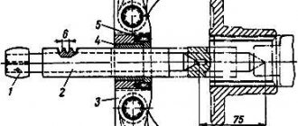
UAZ 469 gearbox device
The UAZ 469 gearbox has the following device:
- input shaft;
- bearing cover;
- input shaft cuff;
- retaining ring;
- input shaft ball bearing;
- secondary shaft roller bearing;
- input shaft spline;
- locking ring;
- synchronizer clutch for 3rd-4th gears;
- coupling hub;
- key;
- 3rd gear spline;
- third gear;
- gear bushing;
- 2nd gear gear;
- crankcase;
- 2nd gear spline;
- synchronizer clutch for 2nd-1st gears;
- 1st gear spline;
- 1st gear gear;
- 1st gear gear bushing;
- secondary shaft roller bearing;
- secondary shaft bushing;
- 5th gear driven gear;
- 5th gear housing;
- double row ball bearing of the secondary shaft;
- spline washer;
- retaining ring;
- secondary shaft;
- bolt;
- support ring;
- 5th gear drive gear;
- splined ring of the 5th gear drive gear;
- synchronizer spring;
- synchronizer block;
- 5th gear synchronizer clutch;
- intermediate shaft ball bearing;
- reverse gear roller bearing;
- reverse gear;
- reverse gear axis;
- gear block for drive of the intermediate shaft and 3rd gear;
- intermediate shaft;
- intermediate shaft roller bearing;
- bearing cover.
UAZ 469 gearbox diagram
Photo 2: Diagram of the UAZ 469 gearbox (Source: Yandex.Pictures)
The diagram of the old-style UAZ 469 gearbox is shown in the top figure. All the main spare parts for the UAZ 469 gearbox and gearbox components are clearly shown here. Products such as boot, oil seal, rubber seals are consumables and are replaced as they wear out. For the UAZ 469 car, the diagram is typical.
The gearbox in the UAZ 469 is attached to the clutch housing with four studs screwed into it. The drive gears of the intermediate shaft, second and third gears are made with helical teeth, the first gear - with straight teeth.
The gears are located on shafts and are in constant mesh. The gears of the first, second and third gears are mounted on the driven shaft on needle bearings. The drive shaft 1 has two supports. The front bearing is located in the crankshaft housing, the rear bearing is located in the front wall of the gearbox housing.
Operating principle
The old-style UAZ 469 gearbox is designed so that to engage 1st gear, the driver needs to move the upper end of the lever 37 with the knob forward and towards himself. After such manipulation, the lower end of the lever enters the transfer head of the 1st gear rod 56, moving it back. The force is transmitted through the fork 49 to the sliding clutch of the synchronizer 12.
It moves along the carriage splines and engages with the ring gear 13 of the first gear of the secondary shaft 16. From the primary shaft 1, torque is transmitted to the drive gear of the intermediate shaft 23. Then through the 1st gear of the intermediate shaft - to gear 13 of the 1st gear of the secondary shaft 16. These two pairs of gears significantly increase torque by reducing the speed of the secondary shaft.
From the gear 13 of the 1st gear of the secondary shaft, torque is transmitted through the ring gear to the synchronizer clutch 12 and then through the carriage to the secondary shaft 16. From the secondary shaft, the torque is transmitted through the splines to the transfer case and then to the transmission units.
When 2nd gear is engaged, synchronizer clutch 12 moves forward. Its internal teeth engage with the ring gear of gear 11. Through the drive gears of the intermediate shaft, then through the 2nd gear of the intermediate shaft, the torque is transmitted to the 2nd gear of the secondary shaft.
From the 1st gear gear of the secondary shaft, torque is transmitted through a ring gear to the synchronizer clutch. The next stage is through the carriage and then onto the secondary shaft.
3rd gear is engaged when the driver moves the synchronizer clutch 9 to the rear position. Gear 10 of the 3rd gear enters its shaft through the hub and synchronizer clutch. Through gear 10, torque is transmitted to synchronizer 9. Then, under the influence of torque, it enters secondary shaft 16.
The 4th gear operates at the moment when the synchronizer clutch 9 connects the primary 1 and secondary 16 shafts to each other. Torque is transmitted directly from one shaft to another, without intermediaries.
Reverse gear is designed in such a way that to engage it, the UAZ 469 gearbox lever must move forward the reverse intermediate gear 25. It engages with its teeth with the reverse gear of the intermediate shaft 23. At the same time, engagement is also carried out with the synchronizer ring gear 12.
Through the intermediate shaft gear 23, the torque is transmitted to the reverse intermediate gear 25. From there, the torque passes to the synchronizer ring gear 12. Next, it engages the secondary shaft 16. In total, when the 3rd gear is turned on, three pairs of gears operate, and the primary and secondary shaft perform multidirectional rotation.
Transmission feature
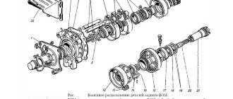
On the UAZ 469, the gearbox is mechanical, designed for 4 stages. At the same time, the 4-speed gearbox is equipped with synchronizers. They are necessary for speed equalization. There are shafts, with the primary shaft based on two supports. The intermediate shaft drive gears are helical. To absorb the occurrence of radial and axial loads during movement, the rear shaft support includes a double-row angular contact ball bearing. This gearbox allows the vehicle to move in reverse. The vehicle is equipped with a transfer case. The UAZ 469 transfer case includes drive axle shafts and gears, which have a long service life.
UAZ 469 gearbox diagram
Transfer case diagram
The advantage of a manual transmission is that it is designed to last a long time. A car that has off-road qualities and is equipped with a manual transmission is excellent for use on rough terrain.
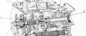
Gearbox UAZ 469, inside view
Conversion of GAZ-69
After some time, a breakdown occurred and I did not patch Trishkin’s caftan, but pulled out the engine, gearbox and transfer case at once.
I started the re-equipment with the installation of a Volgov engine. I secured it with the rear part to the engine cross member, and welded brackets to the frame under the front part using pre-prepared plates.
In order to dock the gearbox with the RK, I had to unscrew the body and raise it by 200 mm.
Having secured the gearbox with the transfer case, I began to manufacture the rear brackets for the transfer case support, and when I secured the transfer case, I removed the rear engine mounts from the yoke.
The time had come to cut out in the body what was preventing it from being put in place, so that in the future, to remove the gearbox and gearbox, you wouldn’t have to remove it again.
When the body was installed, the intermediate axis of the clutch drive had to be shortened and welded again, because it was impossible to put it in place, because it did not fit between the frame and the flywheel housing.
Next, it was the turn of the driveshaft. I couldn’t find the original rear universal joint, so I had to solve the problem using a makeshift method. I took two cardan shafts with the condition that one of them had a normal working splined part. I measured the distance between the flanges of the bridge and the transfer case, and then cut them with this calculation, as it turned out, almost in half.
Then, he took two corners of the thirty and clamped these remains of the cardans with the corners in a vice. The corners acted as centers for me. Then, he placed two electrodes on the cardan forks and aligned the cardan shafts so that they were in the same plane.
The welder grabbed the cardan first from below, and then from above. Next, we released the vice a little and turned the cardan 90 degrees. Again the welder tacked first from below and then from above. Then, the cardan was removed from the vice and the welder welded it in segments on opposite sides. Well, at the end of the process, I welded thoroughly on the second seam.
I did not tear off the balancing plates from the cardans, but left them in their original places. The first time welding the cardan was unusual and a little scary, but while driving it didn’t hit or hum, which means everything went well. Having gradually gotten the hang of it, I welded driveshafts on Volga and UAZ in this way for 10 years, maybe more.
After installing the rear universal joint on the car, it turned out that it was necessary to make a small tunnel under it on the floor of the rear passengers. Also, it was necessary to come up with different lids to close the windows, because... the old ones had to be redone.
The front driveshaft was taken from Bukhanka, but as you know, it is thinner, so I had to shorten it on a lathe.
The exhaust pipe was installed from a UAZ-469, but with some minor modifications. I cut the cross member under the rear of the engine a couple of times so that it would not interfere with the front cardan and attached it to the transfer case at the bottom.
The muffler had to be hung almost like on a UAZ-469 with an exhaust pipe on the rear of the car. I bent the gas control rods, as well as the connections of the water pipes of the engine and radiator. The gas line from the tank to the carburetor ran along the left side of the frame. The air filter was also supplied from UAZ. That's basically all the main changes.
Mechanism adjustment
After assembling and installing the new switching mechanism, it is necessary to adjust the rods and the entire system. The goal is achieved by changing the length of the vertical and horizontal rods. Do-it-yourself setup sequence:
- Move the gear shift lever to the neutral position, and move the element responsible for selecting the gear all the way.
- Move lever 1 to positions corresponding to speeds 1 and 2. While checking that the elements are not pulled up, connect and secure the selection rod.
- Similar actions must be carried out for other gear stages.
After work, you should check that the gears are fully engaged by starting first gear and reverse. The lever must not come into contact with other parts or controls. The optimal gap size is up to 3 mm.
How to disassemble
Before repairing a 5- or 4-speed gearbox (new model), you must carefully study the device diagram, prepare material and tools. To dismantle the unit yourself you will need:
- wrenches: open-end and socket;
- screwdrivers;
- hammer;
- assembly shovel.
The large weight of the product due to contact with the dispensing system requires an assistant during operation and removal of the box.
Disassembling the gearbox occurs in the following sequence:
- Fixing the machine above the inspection hole.
- Removing transmission oil to reduce unit weight.
- Removing the seats in the cabin.
- Dismantling the speed release fork, clutch pan near the muffler, frame, speedometer shaft and cardan.
- Disconnecting the dispensing system from the main structure, securing it to the side with a rope.
- Removing fasteners.
After this, you can remove the body from the car. The next step is to disassemble the gearbox stages, check all elements of the mechanism for wear, and replace non-functional parts with new ones.
Impressions from the car modernization
After upgrading the car, I drove out onto the road and immediately felt the changes. It should be noted that the tires on the car remained the same from the GAZ-69, size 6.50-16; they were narrower than the UAZ ones and somewhat lighter. Therefore, there was no particular point in using the first speed and I easily started off with the second.
The transmission noise became noticeably lower and the car went 80 km/h very easily. If you squeeze the gas to the floor, the GAZ-69 accelerates to 120 km/h, but there is a fair amount of noise in the cabin. Fuel consumption during quiet driving was up to 15 liters per 100 km.
However, along with the advantages, there were also small disadvantages. For example, the traction when driving in mud disappeared. If I sharply pressed the gas, then almost everything that was there flew out from under the wheels, but it was no longer possible to move under tension, as with the previous engine, because the engine just stalled.
On hard roads, greater engine power and better selection of a 4-speed gearbox made it possible to move much faster.
Even on the road, I began to notice that young soldiers, at the first opportunity, climbed into the second row with a great desire to overtake me from the start at the traffic light. Sometimes I took part in these unofficial competitions and at first, oddly enough, I always got ahead. The old GAZ-69 easily escaped the starting line from the newer UAZ-469.
I was helped in this not only by lighter tires and less weight of the old Kozl, but also by the fact that the military UAZ-469 was equipped with gear axles, and they do not provide advantages when starting from a traffic light.
However, all this happened a long time ago; now the ZMZ-409 engine would not leave a chance for victory. Or maybe put the ZMZ-409 on the GAZ-69 and try again?
Source
How to assemble
Assembly and installation of the automatic transmission is carried out in the following order:
- Placing the box in place, tightening the bolts and other fasteners.
- Attachment to the main structure of the transfer case.
- Installation of the speed release fork, clutch pan near the muffler, frame, speedometer shaft and cardan. At this stage you can assemble the lever.
- Installation of seats in the interior.
- Filling the container with new transmission oil.
After this, you can remove the car from the inspection hole. To install a new gearbox on a UAZ and replace other parts, first carefully read the mechanism diagram.
everything useful is here
Removing the gearbox
We work together on the inspection ditch.
We remove the transfer case and install a jack under the clutch housing. Disconnect the wire ends from the reverse light switch. We recommend removing the reverse light switch so as not to damage its terminals. Unscrew the nuts and remove the bolts of the rear supports of the power unit
Using a 12mm wrench, unscrew the four bolts securing the gearshift lever support.
Remove the lever with the spring.
Using a 10mm wrench, unscrew the four bolts securing the clutch cover cover lining.
Using a 19mm wrench, we unscrew the three nuts securing the gearbox (two on the right and the lower left), while the lower left nut rests against the gearbox housing and is not removed from the stud.
Use a jack to slightly lift the power unit (by the clutch housing).
Remove the support plate.
Using a 19mm wrench, unscrew the upper left nut securing the box.
Having moved the gearbox back, we finally unscrew the mounting nuts on the left side.
We remove the gearbox.
Install the gearbox in reverse order. Fill the gearbox and transfer case with oil
When talking about the modernization of the GAZ-69 car, one cannot help but talk about its engine. The M-20 engine, like any other engine, had advantages and disadvantages.
Its main advantage is its high-torque performance. Well, there were two main drawbacks: one of which was the engine life, which was extremely small and if the engine lasted 60 thousand km, then this was considered a good result; the second drawback was the insufficient engine power compared to its competitors.
RK Corps
The transfer case housing consists of two parts. To prevent lubricant leakage at the joint, the parts are sealed with gaskets. Oil seals are installed on the shafts coming out of the sealed housing. They prevent lubricant from leaking out when the car is moving.
REFERENCE: Under load, the lubricant and parts of the lubricant heat up. To avoid breaking the seal of the housing, the manufacturer equipped it with a breathing valve. The device provides communication between the device cavity and the atmosphere.
Drive mechanism
The RK mechanism consists of:
- Rear axle shaft. Rigidly connected to the rear driveshaft of the car. Mounted on ball bearings. They allow the shaft to rotate freely;
- Front axle shaft. Drives the front driveshaft. Fastened with a nut;
- Intermediate shaft. Necessary for engaging the front axle or downshifting;
- Shift forks. Used to move gears when turning the front axle on/off and to downshift. The movement of the forks is carried out along specialized rods. Each fork is equipped with a locking mechanism that prevents spontaneous movement of the product along the rod.
Control mechanism
The unit is made in the form of a metal cover. It is bolted to the transfer case housing. Two levers are installed in the cover. One serves to connect the front axle, the second to reduce the torque transmitted from the gearbox.
REFERENCE: The UAZ 469 transfer case diagram shown above is distinguished by its reliability and high service life. With normal maintenance, the unit can be used for a long time, regardless of operating conditions.
Safety precautions when performing work
To avoid injury when changing the oil in the transfer case, you must:
- Install wheel chocks under the vehicle wheels. This will prevent the car from rolling spontaneously;
- When dismantling the drain plug, it must be kept at a distance from the transfer case. Hot oil from the transfer case can cause burns if it comes into contact with the skin;
- Personal protective equipment such as gloves and goggles should be used to protect eyes and skin.
Assembling a synchronized gearbox
Assemble the gearbox, starting with the subassembly of its components, in the following order:
Assembling the input shaft
Latch the blocking ring onto the shaft cone to a size of 0.8–1.25 mm, as shown in Fig. 36
Press the ball bearing all the way with the sealing ring towards the bearing nut.
Screw on the bearing mounting nut (left-hand thread) and lock it by centering it in the groove of the shaft.
Place grease in the shaft hole and insert the rollers (14 pieces).
Synchronizer assembly
Select a set of couplings and synchronizer hubs with minimal clearances during free movement according to Fig. 37 or use factory-selected kits 469–1701117 and 469–1701138.
Place three springs (Fig. 38), three guide springs, three balls and three crackers in the hub and install the clutch on the hub (the clutch for 1st and 2nd gears is made integral with the reverse gear).
Install the crackers with the side with the smaller diameter holes towards the coupling.
Secondary shaft assembly
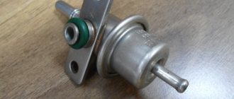
Gearshift lever UAZ 469, 3151
Purpose
In cars with a manual transmission, the lever is a very important element. A knob, lever or gearshift knob are all elements of a car's gear shift system. The peculiarity of these elements in manual transmissions is that the driver must operate them manually. Through the lever, the driver can transmit force to the mechanism for selecting, engaging and deactivating the vehicle's gears. Given the constantly changing loads, speeds and driving conditions, gears must be changed very often, which means that the gear lever must be operated frequently. Thanks to the ability to move longitudinally and transversely relative to the axis of the car, it is possible to select and engage gears. Transverse movement allows for selection, and longitudinal movement is responsible for turning on/off speeds.
Principle of operation
The essence of the operation of a manual transmission is to create connections between the primary and secondary shafts by varying gears with different numbers of teeth, which adapts the transmission to the constantly changing circumstances of the vehicle's movement.
This power unit provides the necessary operating modes of the engine by changing the number of revolutions, changing the transmitted force to the drive wheels. Accordingly, when the number of revolutions decreases, the transmitted force decreases, and when the number of revolutions increases, it increases. This is necessary when maintaining the required engine operating mode when starting to move, reducing speed or accelerating.
Peculiarities
First, this is the sequence of actions when starting the machine:
- depress the clutch pedal all the way and move the gearshift lever to the neutral position; if you have doubts whether the speed has been selected correctly, you need to move the lever handle to the sides; when the gearshift handle is in the neutral position, the lever moves freely to the right and left;
Secondly, the switching pattern for manual transmission. It is most often located on the outer part of the lever handle. When changing gear, it is recommended to focus on the tachometer. You can switch to a higher gear by spinning the engine speed to 1500–2000 rpm in the case of a diesel engine and up to 2000–2500 rpm in the case of a gasoline engine.
Thirdly, the gear shift process. It consists of several stages:
- release the gas pedal;
- Press the clutch pedal all the way with your left foot;
- move the lever by hand to the required position;
- Gently release the clutch pedal and slowly press the accelerator pedal.
Applicability
Sales are carried out from a warehouse in Ulyanovsk. Delivery of the product “Gearshift lever UAZ 469, 3151” is carried out to Moscow, Samara, St. Petersburg, Nizhny Novgorod, Yekaterinburg, Saratov, Krasnodar, Kazan, Perm, Orenburg, Penza and any other cities and regions of Russia.
For regular customers and wholesale buyers, cooperation with us is beneficial thanks to the existing system of discounts, the program of which you can find out from our managers.
The photo of the product card is for informational purposes only. There may be some differences in the completeness and appearance of the original product from the image shown in the photo. For detailed information on the characteristics of the product, contact the manager (Autogur73 store), the call within Russia is free.
Tuning the GAZ M-20 engine
When I returned from the army, I tried to boost the original GAZ-69 engine and to do this I milled the cylinder head so that the valves did not rest against it.
I also pressed out the exhaust valve guides and sharpened them to accommodate the thicker valve stem from the PAZ engine. Next, I drilled the sockets and ground the valves.
They installed PAZ exhaust valves because they had a sodium filler and did not burn even with 76 gasoline. However, the problem was that finding them was extremely difficult.
After carrying out the work described above, the valves stopped burning, and the engine noticeably increased in traction and on a straight road could accelerate the car to 110 km/h. My tuned engine lasted about 15 thousand km, after which water started to flow into the sump.
How much oil is in the manual transmission (gearbox) of UAZ 469
UAZ 469 is an all-wheel drive Soviet SUV, first introduced in 1972. The first modernization took place in 1980. The next restyling took place in 1985. The updated model received a hydraulic clutch drive, a dual-circuit brake system, as well as suspended brake and gas pedals. The UAZ-469 was equipped with a 2.5 liter gasoline engine with a power of 72-75 hp. With. and manual transmission. A two-speed transfer case was also available. The SUV was delivered to Asia, Africa and South America, as well as Italy. In 2003, the car was modernized and renamed Hunter.
- Regulations for changing oil in manual transmission1
- Recommended oil2
- How much oil is required for a UAZ 4693 manual transmission Year of manufacture – 1972-20033.1
The best motor oil. Does it exist?
Regulations for changing oil in manual transmission
According to the recommendations of experienced car owners and specialists, the oil in the UAZ 469 manual transmission must be changed every 50-100 thousand km. Next, we will consider the most favorable conditions for which the specified regulation is suitable.
- A mixed driving cycle is observed with the same mileage on the highway and in the city, without intense overloads and driving at maximum speeds
- Towing of heavy trailers with a volume exceeding the permissible limit for the UAZ Hunter is excluded
- Only original oil or its equivalent is poured into the gearbox.
- The transmission operates without jerking or jerking, gears shift smoothly and effortlessly
- There is no oil leakage from the seals. Their timely diagnosis is necessary to avoid not only oil leakage, but also the occurrence of corrosion processes inside the gearbox. The fact is that if the seals are not sealed properly, water can pass through them, for example, in rainy weather. The oil seals must be urgently replaced, then the box must be rinsed to remove any dirt deposits and new oil must be added.
Recommended oil
- Original – TAD-17; 80W-90 GL-4
- Alternative – Mobile, Castrol, Shell
Engines installed on GAZ-69
Soon the UAZ-469B car went into production, and since Since the new car was much more dynamic and comfortable than previous models, most GAZ-69 owners began installing UAZ and Volgov engines in their cars.
However, among the adherents of more powerful engines, there were also those who were partial to the engine from the UAZ-450. Due to the fact that it had a piston with a diameter of 88 mm, the engine power reached 62 hp.
I somehow came across such a cylinder block, but pistons and rings for it were in real short supply at that time and I was unable to find them. I must say that the only time I accidentally saw such a rare engine assembled in scrap metal. After such a meeting, I became a little interested in restorers of old equipment, because they find exclusive parts somewhere.
There was another engine in the USSR that was chased by Kozlikov lovers and which was valued much higher among foresters and hunters than the Volgovsky. It was a Polish engine from a Nysa car.
In its pedigree, this engine had roots from the GAZ M-20 engine, but was modernized by the Poles while maintaining the old dimension and converted into an overhead valve. With an engine power of 70 hp, it pulled like crazy at the bottom and when driving tight, it had absolutely no competitors.
Based on the above, the real contender for me for installation on the GAZ-69 car was the Volgovsky engine from the GAZ-21. However, preparations for the operation to install another engine took time and in my case took a lot of time.
Around the same time, I came across an interesting article about the modernization of production processes and it concluded that it makes no sense to separately reconstruct one workshop in production, because this will not lead to an increase in output throughout the enterprise.
After reading this and thinking a little, it became clear to me that if in my case I installed a more powerful engine, then I would also need to install a gearbox and transmission from a UAZ. Only then will I receive maximum benefit from the planned refurbishment. To put it simply, after the conversion I will have a modern UAZ in the skin of the GAZ-69.
Service station or self-repair?
It is this question that often makes bus owners think. In this case, it is recommended to proceed from the specific situation. There are minor malfunctions, to eliminate which it is enough to tighten a few nuts, which is quite possible to do yourself.
If you are faced with a serious breakdown of the UAZ 452 gearbox, it is advisable to turn to professionals. Moreover, you need to focus on a service station that specializes in transmission repair. One of them is an atelier in St. Petersburg, whose services can be found on the portal spb-avtoremont.ru.
A distinctive feature of this service station is its specialization in the repair of mechanical transmissions, transfer cases and engines. This allows craftsmen to work with boxes, regardless of model and year, and also maintain reasonable prices. In particular, the price for repairing a removed gearbox starts at 3,000 rubles. In addition, station employees, if necessary, help the client find spare parts.