We repair ZF truck gearboxes
85
We accept truck gearboxes for repairs using the trade-in system
Repair of gearboxes and gearboxes within 12 hours
Free oil change in internal combustion engines, gearboxes, RMZ
Our service guarantee
Team of professionals
More than 10 years of successful work
The optimum ratio of price and quality
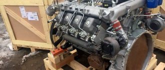
Truck Aggregate cargo service offers diagnostics and repair services for mechanical and automatic transmissions of trucks. We restore the transmission to 90% new condition by ultrasonic cleaning every part, and also replace every worn element. These works are carried out by our mechanical specialists who have extensive practical experience in this field, usually at least 5 years.
We repair ZF gearboxes for the following truck models:
- MAN TGA, TGS, TGX - boxes 16s181, 16s151, 16s109, 16s2220;
- DAF XF 105 - gearboxes 16s181IT, 16s2333;
- Renault Premium - transmissions 16s181, 16s151, 16s109, 16s2220;
- IVECO - 16s151, 16s221, 16s1920TD, 16s2220 TD, 16s2220TO, 16s2225TO.
To repair ZF gearboxes, spare parts from leading manufacturers Euroricambi, Ina, Fag, Skf are used. Spare parts for ZF boxes are available in stock. We coordinate all work with the client in advance. Major repairs are carried out within 12 hours. We always have a fixed price and a guarantee for repairs.
Long-distance-mangruzovik.ru. Instructions for repairing special equipment.
1-DEVICE OF SERVO DRIVE OF THE GEAR SHIFTING MECHANISM,
2-DIAGRAM OF OPERATION OF THE PNEUMOSYSTEM WHEN ENGAGED IN LOW RANGE GEARS,
3-DIAGRAM OF PNEUMOSYSTEM OPERATION WHEN HIGH RANGE GEARS ARE ENGAGED,
4-DIAGRAM OF OPERATION OF THE PNEUMOSYSTEM IN THE LOWER GEAR MODE,
5-DIAGRAM OF OPERATION OF THE PNEUMOSYSTEM WHEN NORMAL GEARS ARE INCLUDED,
6-PLANETARY REDUCER CONTROL SYSTEM.
The ZF 16 S 181 - 16 S 221 gearbox modification DD (with direct transmission) or OD (with overdrive) consists of the following components:
— The middle crankcase, which houses the input shaft, drive shaft, secondary shaft and gears for four forward gears and one reverse gear.
- Rear housing, which houses an planetary gear unit (“ERU”) with helical gears, which serves to double the number of forward gears. Thus, the number of gears increases from four to eight (4 normal and 4 low).
— A front housing in which a divider is installed, allowing each of the eight forward gears and one reverse gear to be further divided into two. The divider thus creates another gear between two successive gear ratios, so that each gear is divided into low and high (L and S, respectively).
Thus, these gearboxes have 16 forward gears with close ratios that can be engaged sequentially, and two reverse gears.
Synchronizers are single-cone type. Lubrication is carried out using a gear pump.
The “double H” type gear shift mechanism is equipped with a pneumatic servo drive, facilitating the process of selecting and engaging a gear.
The servo drive includes a pneumomechanical module and a bidirectional spool.
The advantages of this device are: - Reduced physical effort and reduced time for gear shifting. — Reducing vibration of the lever control mechanism, reducing noise levels. — Reducing the load on synchronizers. If the pneumatic system fails, the drive operates as a mechanical one.
GEAR SHIFT SERVO DRIVE 1. Control spool lever - 2. Gear shift lever - 3. Guide pin - 4. Air release hole - 5. Control spool piston - 7. Spool body. — 8. Return spring — 9. Lever connecting to the longitudinal rod.
OPERATING PRINCIPLE Low range gears
OPERATION DIAGRAM OF THE PNEUMUS SYSTEM WHEN LOW RANGE GEARS ARE ENGAGED Compressed air Air from the receiver is supplied simultaneously to the retarding valve (14) and to the selector valve (1) via the air line (15).
When the selector valve (1) is switched to the lower position (position L - low range gears), air through the selector valve (1) flows through the air line (16) to the bidirectional control spool (8).
Air supplied under pressure to the above-mentioned spool (8) moves the pistons (4 and 9) to the left.
As a result of the movement of the pistons (4 and 9), the valve (7) closes (sits into place) and air is released from the left chamber of the divider drive cylinder (2) into the atmosphere through the corresponding channel (12).
At the same time, valve (6) moves and opens. Air through the inlet duct (11) and line (3) is supplied to the right chamber of the divider drive cylinder (2).
When you press the clutch pedal, air from the retarding valve (14) is supplied to the bidirectional control spool (8) through the air line (13).
The air entering the spool (8) passes through the inlet port (11) and freely enters the right chamber of the divider drive cylinder (2) through the connecting line (3).
The piston of the divider drive cylinder, moving to the left, shifts the entire drive to the lower level, thus ensuring the engagement of low-range gears.
OPERATION DIAGRAM OF THE PNEUMUS SYSTEM WHEN HIGH RANGE GEARS ARE ENGAGED
Air from the receiver is supplied simultaneously to the retarding valve (14) and to the selector valve (1) via the air line (15).
When the selector valve (1) is switched to the upper position (position S 5 of the high row gear), the flow of air through the air line (15) into the bidirectional control spool is stopped, and the line (16) is connected to the outlet pipe (17).
As a result, air is released from the bidirectional control spool (8), and under the action of spring (10) and springs (15), the pistons (4 and 9) move to the right.
As a result of the movement of the pistons (4 and 9), the valve (6) closes (sits into place) and air is released from the right chamber of the divider drive cylinder (2) into the atmosphere through the line (3).
At the same time, valve (7) moves and opens. As a result, air is supplied through the inlet channel (11) and the line (3) into the right chamber of the divider drive cylinder (2).
When you press the clutch pedal, air from the retarding valve (14) is supplied to the bidirectional control spool (8) through the air line (13).
The air entering the spool (8) passes through the inlet port (11) and freely enters the right chamber of the divider drive cylinder (2) through the connecting line (12).
The piston of the divider drive cylinder, moving to the right, shifts the entire drive to the upper level, thus ensuring the engagement of high-row gears.
PLANETARY GEAR CONTROL SYSTEM Low gears Figure 4
OPERATION DIAGRAM OF THE PNEUMUS SYSTEM IN THE LOW GEAR MODE
The air pressure coming from the pneumatic system is reduced by the pressure reducer (1) to 9.5 bar. Air is then supplied to retarding valve D.
Now, when the gear shift lever is turned to the lower gear position (first H), part A, which is an integral part of the gear shift rod, opens valve E, which supplies air to cylinder G through line F.
The piston of cylinder G, moving to the right, activates the planetary gearbox "ERU"
At the same time, valve B closes and air from line C is released into the atmosphere.
As a result of the movement of the piston, the contacts of the electrical switch close, and an indicator with the image of a turtle turns on in the driver's cabin.
Normal gears Figure 5
OPERATION DIAGRAM OF THE PNEUMUS SYSTEM WHEN NORMAL GEARS ARE INCLUDED
The air pressure coming from the pneumatic system is reduced by the pressure reducer (1) to 9.5 bar. Air is then supplied to retarding valve D.
Now, when the gear shift lever is turned to the normal gear position (second H), part A, which is an integral part of the gear shift rod, opens valve B, which, through line C, supplies air to cylinder G.
The piston of cylinder G, moving to the right, turns off the planetary gearbox “ERU”.
At the same time, valve E closes and air from line F is released into the atmosphere.
As a result of the movement of the piston, the contacts of the electrical switch open, and the indicator in the driver's cabin turns off.
ZF Technical Documentation Catalog
S 5-42 (1307.050.363 PAVLOVO BUS) S 5-42 (1307.050.366 KAMAZ) 6 S 800 TO (1346.001.007) 6 S 850 (1290.055.130) 6 S 700 BO (1351.001.017 KAVZ) 6 S 1200 (1350.003.037 KAMAZ) 8S 1350 (1295 095 074 KAMAZ) 9 S 1310 TO (1324.001.048 KAMAZ) 9 S 1310 TO (1324.001.098 KAMAZ) 12 AS 2331 TD (1353.041.012) 12 AS 2301 IT (1327.040 .034) 12 AS 2301 IT (1327.040.059 MAN) 16 S 151 (1315.051.141) 16 S 151 (1315.051.760) 16 S 151 (1315.041.711) 16 S 151 (1315.051.947 IVECO) 16 S 151 ( 1315.051.989 RENAULT) 16 S 151 IT (1315.041.719) 16 S 181 (1316.055.
009) 16 S 181 (1316.055.139) 16 S 181 (1316.055.200) 16 S 181 IT (1316.04) 6.102 1316.055.108 MAN ) 16 S 221 (1316.051.196) 16 S 221 (1316.051.743) 16 S 221 (1316.051.935) 16 S 221 (1316.051.905 IVECO) 16 S 221 IT (1316.041.103 1316.051 .118 DAF TRUCKS) 16 S 251 (WSK 4130.065.212) 16 S 1650 (1297 095 111 MAZ) 16 S 1820 TO (1341.002.054 COMESA-MAZ) 16 S 1820 TO (1341.002.074 KAMAZ) 16 S 1920 TD (1342.001. 001) 16 S 1920 TD (1367.001.030 IVECO) 16 S 2220 TD (1356.001.031 IVECO) 16 S 2220 TO (1342.002.001 MAN) 16 S 2220 TO (1367.002.
030 IVECO) 16 S 2225 TO (1367.031.012 IVECO) 16 S 2230 TD (1356.001.040) 16 S 2331 TD (1356.052.026) 16 AS 2231 TD (1328.042.009) 16 S 2520 TO (134 3.002.056) 16 AS 2601 IT (1328.040.024 / 1328.001.049) 4 WG 160 (4656.054.117) 4 WG 200 (4644.024.146) 6 WG 190 (4657.026.105)
The world-class company ZF is considered one of the leaders in the car market in the production of equipment. ZF catalog presents a wide range of spare parts for any type of transport. The most common use of these products is for passenger cars and commercial vehicles.
The company guarantees the high quality and reliability of its products.
Application of ZF spare parts on different types of transport
The range of spare parts, in addition to systems and components of gearboxes, such as zf 16 - a manual gearbox designed for heavy-duty vehicles - up to 40 tons or zf 9s1310 - a 9-speed gearbox for medium-duty trucks, includes suspension components, chassis and transmissions for various types of vehicles:
- passenger car;
- cargo and commercial - zf 16s151;
- buses;
- motorcycles;
- various construction equipment.
The use of Polar Division innovations in passenger vehicles increases efficiency, safety and operating comfort. ZF gearbox control systems, used on trucks and commercial vehicles from the 9-speed zf 9s1310 gearbox to the zf 16s181 designed for heavy-duty vehicles, significantly increase their operating efficiency. The components used in passenger transport make it more attractive and its operation more economical. The products guarantee mobility when operating any type of transport in any conditions.
The entire range of products, from zf 2 to 16-speed gearboxes
Despite the fact that the specialization of the German concern's products is quite wide, its most common use is in passenger cars, trucks and commercial vehicles. The product catalog presented on our website today includes the following units and components:
- manual gearboxes for various types of transport, including zf 2 and gearboxes for heavier-duty vehicles zf 16s181;
- automatic transmissions for cars and trucks;
- clutch;
- power steering;
- drive axles and suspension systems;
- various components for industrial vehicles, including clutches, brakes and gearboxes.
Series 6S for Kamaz light trucks.
Light delivery trucks are equipped with 6S series gearboxes.
Technical characteristics of 6S 700:
Number of gears: 6 Gear ratios: 6.02 – 0.79 Maximum torque, N*m (kgf*m): 700 (71) Oil volume for pouring, dm 3: 6.0 Gearbox weight, net, kg: 103 First change oil after: 1,500 km (maximum - 5,000 km) Secondary change every: 90,000 km (maximum - 120,000 km) But not less than: 1 time per year Applicability: KAMAZ, KAVZ, and others
On the 6S gearbox, due to the close location of the output shaft for the PTO, an offset box is installed, which allows the installation of a pump.
ZF EcoSplit 16S gearboxes for heavy-duty Kamaz vehicles
ZF EcoSplit 16S 1650, 16S 1820 are designed for heavy trucks with engines from 320 to 500 hp. power
Gearbox ZF 16S 151, 16S 181, 16S 221, 16S 251
Series: 16S Gearbox type: mechanical Number of gears: 16 Gear ratios: 16.41 – 1.00 Maximum torque, N*m (kgf*m): 1600 (163) Oil volume for pouring, dm 3: 13.4 Gearbox weight, net, kg: 278 First oil change after: 1,500 km (maximum - 5,000 km) Secondary change every: 90,000 km (maximum - 120,000 km) But not less than: 1 time per year Applicability: Kamaz, MAZ, and others
The modern ZF-Ecosplit synchronized gearbox consists of a unit with 4 gears, a range and a front divider. Designed for high loads, it allows you to choose the most optimal movement option; synchronization of the divider and range-multiplier makes gear shifting smooth and guarantees reliable and long-term use of the gearbox.
The Servoshift servo mechanism consists of a mechanical-pneumatic control unit and a double-acting pneumatic cylinder, which greatly facilitates and automates the control of switching between lower and higher stages.
Prices for basic work
| Name of service | Price, rub * |
| Computer diagnostics of the node | from 1600 |
| With/a cargo gearbox | from 12800 |
| C/U gearbox ZF tractor | from 12800 |
| C/U gearbox ZF tractor with retarder | from 14200 |
| C/u gearbox ZF single | from 14200 |
| C/U gearbox ZF special equipment | from 18000 |
| Troubleshooting | from 7500 |
| Assembly | from 10000 |
| Change of oil | from 1400 |
| Checking the oil level | from 500 |
| Replacing the clutch (with removing the box) | from 14200 |
| Cardan shaft, removal/installation | from 2000 |
| Power take-off (if present) | from 3500 |
| Transmission support, removal/installation | from 2500 |
| Input shaft oil seal (with gearbox removed), replacement | 14200 |
| Replacing the shank seal | 2000 |
| Replacing cables | 5600 |
| Clutch fork repair | 1500 |
* — the cost of a standard hour is 1400 rubles.
* - the cost of work may vary depending on the type of car and its technical condition. Due to the fact that it is impossible to provide a full price list due to the large volume of work performed, we suggest you call the specified number or send a request for car diagnostics via the contact form communication and calculation of repair costs.
We also draw your attention to the fact that the standard time for performing a specific operation is taken from the current regulatory framework of the vehicle manufacturer. To calculate the cost of work performed, it is necessary to multiply the number of standard hours (standard time for completing a work operation) by the cost of one standard hour.
Sign up for diagnostics
Operation of the ZF gearbox
To extend transmission life and achieve significant fuel savings, follow these guidelines.
- Try to keep the engine speed always in the middle range for each gear. Use the highest available gear in each speed range.
- Always fully depress the clutch when changing gear, this will prevent increased wear on the gearbox synchronizers.
- ZF gearboxes, which are installed on Kamaz trucks, are equipped with synchronizers; they allow you to change gears quickly, without excessive effort and almost silently. There is no need to double-depress the clutch when moving from lower to higher gears, and vice versa.
Source
Carrying out repair work
Proper maintenance of this unit helps to avoid premature repair of the ZF gearbox. In particular, the motorist must independently monitor the oil level. Its excess or deficiency is the reason why the car system fails. By choosing synthetic oils, the driver extends the life of the box and its component parts.
It is better to order ZF gearbox repair at a service center. Here, using the defect detection method, it will be possible to accurately determine what type of malfunction exists on the car. The oil is drained, which must be checked for its external condition, whether it is cloudy or not. It is advisable to measure the axial play of the shafts, after which the repair of the ZF gearbox begins (disassembling the box). At this stage, worn parts are detected that need to be replaced. Also, the system is monitored for cracks and chips. It is important to disassemble the gearbox if the gearbox temperature is high.
As a rule, when a ZF gearbox needs to be repaired, the shafts are changed, including the shaft that belongs to the range, synchronizers, gears, and control valves.
Thus, repairing a ZF gearbox involves disassembling the gearbox, after which worn parts must be replaced.
Zf gearbox divider valve repair kit
- home
- Spare parts __/catalog/__
- Technical information __/catalog/tehinfo/__
- __/catalog/tehinfo/kppzf/__
- __/catalog/tehinfo/kppzf/kppzf-16s/__
- __/catalog/tehinfo/kppzf/kppzf-16s/remont-kppzf16/__
Back
Disassembly of the ZF 16S gearbox is carried out after removing the box from the car. Also, before disassembling the gearbox, it is necessary to clean it. A condition for carrying out repair work is the use of tools recommended by ZF.
After disassembly, be sure to clean all components of the ZF 16S gearbox . This applies primarily to corners, pockets and inclined surfaces of the body and covers.
Carefully remove caulk and flat seals. Check lubrication holes, grooves and lines for free passage. They must be free of deposits, foreign bodies or preservatives. The last requirement applies primarily to new parts.
Parts accidentally damaged during disassembly of the ZF 16S gearbox must be replaced with new ones (for example, shaft sealing rings, O-rings, U-shaped seals, caps, protective caps, etc.). Parts such as rolling bearings, shims, synchronizer parts must be checked by a specialist who will give an opinion regarding the possibility of their further use.
Flat seals are installed dry, i.e. free of oil or grease. Places where the use of flat seals is not provided are sealed using a heat- and oil-resistant sealant of plastic consistency (for example, type WEVO-L 100 A).
Disassembling parts of the range multiplier
1.1. Plastic pipelines
NOTE: Before dismantling, mark the pipelines according to their connections.
Remove the hollow bolts 1 and 2 from range cylinder 3 and range activation valve 4. Loosen the clamp 5 on the crankcase and completely remove the pipelines.
- Remove lock washer 1 from bolts 2.
- Stop the output shaft flange from turning.
- Remove the hex head bolts 2 and the clamping washer 3.
- Place the spacer on the planetary gear carrier and, using a puller with two or three jaws, remove flange 4.
- Remove O-ring 5.
- Unscrew the hexagonal head bolts and remove cover 1 with gasket 2.
- Unscrew the hexagonal head bolts and remove the cover 3 along with the gasket 4, cuff 5, compensating washer 6 and ball bearing 7.
- Using a plastic drift, remove the ball bearing from the cover. Remove the loose compensating washer. NOTE: With helical gears, the ball bearing is located on the output shaft. In this case, it should be removed using a puller. It should be borne in mind that in some designs of boxes for removing a ball bearing, a puller 1X56 122 314 is required, which has not ten, but eleven legs.
- Using a plastic mandrel, remove the cuff from the cover.
Rear splitter disassembly
1.4. Divider activation valve
- Remove the divider switch valve 1 of the ZF 16S gearbox
- Be careful not to lose O-ring 2. NOTE: The valve cannot be disassembled - it is a single piece. NOTE: The gearbox type 8 S 151 does not have such a valve.