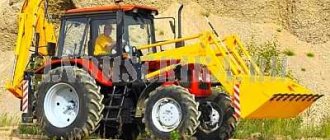
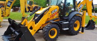
The British company JCB is known throughout the world for its high quality tracked and wheeled construction equipment. Backhoe loaders occupy a special place in the company’s product range. One of the most famous models of such equipment is the JCB 3CX Super. The vehicle is equipped with a proprietary diesel engine.
Unlike most construction equipment manufacturers, JCB pays a lot of attention to the design and ergonomics of its products. In this article we will take a closer look at the JCB 3CX Super backhoe loader. This instruction manual and reviews from real operators will help us.
A little history
JCB was one of the first manufacturers of backhoe loaders. The company’s “firstborn”, released back in 1954, was called Major Loadall MK. It was a regular tractor with a Fordson engine, a cable loader and excavator attachments. At that time, 550 units rolled off the assembly line.
Since 1956, a new model was launched, which was called Hydra-Digger. It featured longer excavator equipment. Until 1960, about 1,800 of these models were produced. At the same time, development of our own chassis began, which led to the creation of the JCB4 model. It was the first backhoe loader to feature the signature yellow color and a 180-degree rotatable seat. Over three years of production, one and a half thousand copies were sold.
Between 1961 and 1967, approximately 7,000 JCB 3 models rolled off the production line, featuring a movable carriage, supports and new excavator equipment. In 1963, some changes were made to the model. In particular, a hinged side door, an extended handle, and a new engine (Fordson or BLMC) were installed. And the index “C” was added to the name.
The new generation, released in 1967 under the name JCB 3C II, became a real long-liver. It was produced until 1980. In thirteen years, about 40,000 copies were sold. This version was distinguished by a curved arrow and a sliding door. Later modifications received a semi-automatic transmission and a pneumatic boom.
The next long-liver was put into production in 1980. Its name was JCB 3CX. The use of a double-jaw bucket allowed this version to dig holes up to 5.53 meters deep. Past modifications were limited to four meters. The 3CX model was produced for 11 years and sold 74,000 copies worldwide. It is so reliable that it still serves faithfully on construction sites.
In 1990, the JCB 2CX backhoe loader appeared, which has a 4 x 4 x 4 wheel arrangement. And 1991 became a turning point for the company. The 3CX model was completely redesigned: from the chassis to the design. At the same time, the company launched the production of a powerful all-wheel drive JCB 4CX model, which had coordinated turning of all wheels and the so-called “crab drive”.
In 2002, the company focused on design. It introduced a servo drive as well as a Powershift transmission into its flagship model. And 2005 was marked by the release of an updated model with a solid hood, new hydraulics, its own engine and a number of other less significant changes. This is where the story of our today's hero began.
Cabin
Like all its siblings, the JCB 3CX Super has a spacious, rounded cab. Its characteristic features are tinted windows and the absence of crossbars. This appearance has become one of the symbols of the British brand's products. The cabin design turned out to be very successful and comfortable. However, there is also a drawback - for the sake of aesthetics, all glass is glued into the openings. Considering the specific nature of the operation of such equipment, the risk of glass damage is quite high. And replacing it is now a labor-intensive and lengthy process. Excavator and loading booms are externally in complete harmony with the cab and chassis.
Device
The model has a two-axle all-wheel drive pneumatic chassis. The driver's cabin is located in the rear, the power plant is in the front.
The JCB 3CX gearbox was designed specifically for this equipment. The model is equipped with two types of gearboxes:
- Powershift with reverse and one shift lever located on the steering column;
- Syncroshuttle is electrically controlled and has a torque converter for smooth gear changes on the fly.
The triple brake system provides efficient and reliable braking. Due to the fact that self-regulating disc brakes operate in an oil bath, their properties are maintained even after several years of operation.
The backhoe loader is equipped with an Open Center hydraulic system that maintains optimal speed and hydraulic power. Depending on the type of conditions, the system automatically selects the necessary parameters, ensuring the greatest efficiency.
The operator’s cabin of the “troika” is made in accordance with ROPS/FOPS requirements. Large glass area (6.5 sq.m.) and excellent visibility contribute to increased safety. Additionally, the operator's cabin is equipped with:
- EasyControl servo control system, which optimizes the speed of extension of the shovel hydraulic cylinder rods;
- alternative hydraulic control system AdvancedControl.
The operator's cabin again houses an hour meter, coolant temperature and fuel level indicators, a tachometer, gauges, indicators and a clock. Two large halogen headlights, four work lights and two tail lights keep the illumination at the proper level even in bad weather.
The design of the operator's cabin turned out to be very successful. The only negative was the location of the glass, which is glued into the openings. This often leads to their damage, and replacement takes quite a long time.
How much does a new and used JCB 3CX backhoe loader cost?
The cost of the new JCB 3CX is in the range of 3-3.5 million rubles. Taking into account the number of hours worked and the year of manufacture, you can find options for 1.5-2 million rubles.
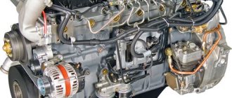
Motor
As already mentioned, one of the main distinguishing characteristics of the 3CX Super backhoe loader is the engine. It was developed specifically for this model. The JCB 3CX Super engine, according to the company, has a huge reserve of torque almost from idle. Many original solutions were made in the design of the engine cooling and power supply systems. So, we installed a water separator filter. It traps moisture trapped in the fuel. The oil filter was equipped with a counterflow valve. It holds the oil in the housing when the engine is turned off. This solution not only makes maintenance more comfortable, but also makes it possible to start the engine on clean, filtered oil.
The air supply system has a self-cleaning filter. The air intake was moved a little to the side. This makes the incoming air cleaner and cooler. They also took care of the ease of servicing the motor - all service points are located on the left side. So you no longer need to walk around the excavator to get this or that element.
Slip limit differential
An automatic feature on some vehicles, this should be distinguished from a differential lock. In difficult conditions, traction can be increased. This means that a larger proportion of the existing torque is transmitted from the rotating wheel to the drive wheel. If the wheel slips, it means that the limited limit has already been reached.
When the slip limiting differential is engaged (and especially when the steering mechanism is completely locked), if work is carried out on a surface with good grip, such as concrete, noise and vibration may occur. Their intensity is determined not only by the conditions of the coating, but also by the weight of the excavator, the angles of rotation - and this sound does not indicate damage to the axle.
Interior
Inside the cabin, everything is strict, restrained and very comfortable. The predominant colors are black and gray. Together with tinted glass, they give the interior a certain elegance. The interior layout has remained virtually unchanged since 1997. And this is not archaic at all, but time-tested convenience and ergonomics.
The cabin has two workstations. One of them is provided for the loader operator. The steering column has become a little “slimmer”. It has two steering column levers. The first controls the transmission, and the second controls the lighting equipment. Below the steering wheel is an indicator panel. It is topped with the JCB emblem. Having turned the chair 180 degrees, we find ourselves at the excavator operator’s workplace.
Here everything is done according to the traditional scheme for passenger cars. To the right is the glove compartment and to the left is the JCB 3CX Super instrument panel. Reviews from people who have worked with this equipment show that the ventilation system deserves special attention. Firstly, diffusers are scattered throughout the cabin, they do their job perfectly. And secondly, the operator has the ability to open the rear window.
Armchair
In this technology, special attention is paid to driver comfort. After all, working with a backhoe loader is quite complex and responsible. In terms of adjustments, the driver's seat is not inferior to modern passenger cars. Its height is modified in three versions: the entire chair, the front and the back.
Thanks to the compressor, you can adjust the level of support separately on the lower part of the backrest and on the upper one. For comfortable work in the cold season there is electric heating. Anyone can sit comfortably in the JCB 3CX Super chair. There is excellent visibility from the driver's seat. The front wheels and loader boom are clearly visible.
Video
As a result, the British managed to achieve optimal efficiency and payback indicators, which became a record in this class. The use of advanced technology in the backhoe loader has reduced noise and emissions and achieved additional fuel savings of 16%. Thanks to longer refueling intervals, the JCB 3CX's performance has been significantly improved.
The advantages of this model do not end there. It is valued for its versatility. The backhoe loader is used in almost any conditions: on a construction site, on rough terrain and within the city. Good cross-country ability and versatility of the JCB 3CX model are ensured by large equal-sized wheels. The special equipment has two driven steering axles, and the “track to track” mode allows you to turn the front and rear wheels in different directions. Backhoe loader hydraulic hoses operate in temperatures down to -40 degrees, and all components are tested to withstand sunlight, chemicals, oil, extreme temperatures and salt.
Control
In budget versions, the bucket and loader are controlled using simple levers. On more expensive trim levels it is assigned to three joysticks. One of them is responsible for the loader, and the other two are responsible for the excavator. Joysticks take over some of the functions of pedals. This opens up the possibility for the driver to work with the seat turned to the side. In inexpensive versions, the excavator is controlled by two levers. The right one is responsible for turning the bucket and raising/lowering the boom, and the left one is responsible for moving the bucket and turning the boom.
In this case, the pedals are responsible for only one function of the JCB 3CX Super - the telescope. How to adjust the telescopic boom extension? Quite simple. Expert reviews show that the pedals work well. And if you turn on the corresponding toggle switch, you can assign another function to them - shifting the excavator carriage. This is very useful, especially in urban environments.
Adjusting the supports also does not present any difficulties. This is done using levers located next to the dashboard. This is another highlight of this model. Another feature is the absence of a hydraulic hammer and wiring for it. During simple movement, the boom is locked with a lock, which can be unlocked using a special handle. It is located near the cup holder. A special toggle switch activates the bucket leveling system, which helps protect its contents from spilling.
Transmission
It was already mentioned above that the 3CX Super model is equipped with a semi-automatic Powershift transmission. Depending on the modification, it can be 4- or 6-band. Another difference between the cheap versions and the expensive ones is the absence of the “crab move” function. But on all variations the possibility of coordinated rotation of 4 wheels is available. It is also activated using a special toggle switch. Takes effect as soon as the wheels are aligned. This option greatly increases the maneuverability of the equipment, allowing you to work comfortably in tight spaces.
JCB error codes (hydraulics and electronics)
| Error codes | Inscription on the monitor display | Description of the malfunction |
| 101 | CRANK | ECU1 does not detect a signal from the crankshaft. |
| 102 | FUEL | Fuel sensor circuit open |
| 103 | EN TMP | The engine temperature sensor circuit is open. |
| 104 | HYD TMP | The hydraulic fluid temperature sensor circuit is open. |
| 105 | SET PT | The throttle position potentiometer circuit is open. |
| 106 | SENS PT | The actual throttle position potentiometer circuit is open. |
| 107 | OIL SW | The oil pressure sensor provides a pressure signal when the engine is off. |
| 108 | FLYWHEEL | The cardan drive sensor produces an engine speed signal when the |
| 109 | ALT | The generator provides a voltage signal when the engine is turned off. |
| 110 | THR SOL | The throttle valve solenoid circuit is open. Detected only when the engine is switched off. |
| 111 | BOOM SP | Boom low speed control circuit is open. |
| 113 | MAX FLW | The maximum flow solenoid valve circuit is open. For JS200W machines, this error can only be detected |
| 115 | BOOM | Priority Solenoid Valve Circuit Open |
| 116 | FL PMP | The refueling pump output circuit is open. |
| 117 | HORN | The horn output circuit is open. |
| 118 | HYD PMP | The hydraulic pump circuit is open. Since the valve is proportional, the error is only detected when the motor is switched off |
| 119 | SLW LCK | The boom lock solenoid valve circuit is open. |
| 120 | HYD FAN | The hydraulic fan output circuit is open. Detectable only when the engine is off |
| 121 | SLW BRK | Boom release solenoid valve circuit open |
| 122 | SLW ST | The boom cut-off solenoid valve circuit is open. |
| 127 | TL CHNG | The speed shift solenoid valve circuit is open. |
| 128 | WASHER | The washer motor circuit is open. |
| 129 | DOZER | Blade solenoid valve circuit is open. |
| 130 | GRB CW | The clockwise rotation solenoid valve circuit is open. |
| 131 | GRB CCW | The grab counterclockwise rotation solenoid valve circuit is open. |
| 132 | LW FLOW | Low flow solenoid valve circuit is open. |
| 133 | ISOL | The waterproofing solenoid valve circuit is open. |
| 135 | 2 STAGE | Stage 2 safety solenoid valve circuit is open. |
| 136 | QK HTCH | The quick hitch solenoid valve circuit is open. |
| 138 | HAMMER | The hammer solenoid valve circuit is open. |
| 139 | CUSHION | The hard/soft cushion solenoid valve circuit is open. |
| 142 | ENG SD | The engine shutdown output circuit is open. |
| 143 | GLW PLG | The glow plug output circuit is open. |
| 156 | TL FLW3 | The 3 motion flow solenoid valve circuit is open. |
| 157 | TL FLW2 | Flow 2 solenoid valve circuit is open. |
| 158 | GR CHNG | M2 solenoid valve or gear shift circuit is open. |
| 159 | BRKE LT | The brake lamp output circuit is open. |
| 160 | AXLE LK | The axle lock solenoid valve circuit is open. |
| 161 | STAB UP | The stabilizer lift solenoid valve circuit is open. |
| 162 | STAB DIN | The stabilizer lower solenoid valve circuit is open. |
| 163 | STAB LH | The left stabilizer solenoid valve circuit is open. |
| 164 | STAB RH | The right stabilizer solenoid valve circuit is open. |
| 165 | CRUISE | The cruise control solenoid valve circuit is open. |
| 166 | DIG ISL | The cutting edge isolator solenoid valve circuit is open. |
| 167 | PRK BK | The M1 solenoid valve or parking brake circuit is open. |
| 168 | DRV ISL | The drive isolator solenoid valve circuit is open. |
| 202 | FUEL | Short circuit of the fuel level sensor circuit. |
| 203 | EN TMP | Short circuit of the engine temperature sensor circuit. |
| 204 | HYD TMP | Short circuit of the hydraulic fluid temperature sensor circuit. |
| 205 | SET PT | Short circuit of the throttle position potentiometer circuit. |
| 206 | SENS PT | Short circuit of the actual throttle position potentiometer circuit. |
| 210 | THR SOL | The throttle solenoid valve circuit is short circuited. Detected only when the engine is switched off. |
| 211 | BOOM SP | Boom low speed control circuit short circuited. |
| 212 | INT LT | Interior lighting circuit short circuit. |
| 213 | MAX FLW | Maximum flow solenoid valve circuit short circuited. For JS200W machines, this error can only be detected when the engine is turned off, since these machines have a proportional valve. |
| 214 | BEACON | Short circuit of the beacon circuit. |
| 215 | BOOM PR | Priority solenoid valve circuit short circuit. |
| 216 | FL PMP | Short circuit in the refueling pump solenoid valve circuit. |
| 217 | HORN | Horn circuit short circuit. |
| 218 | HYD PMP | Short circuit in the hydraulic pump circuit. Since the valve is proportional, the error is only detected when the motor is switched off. |
| 218 | HYD PMP | Short circuit in the hydraulic pump circuit. Since the valve is proportional, the error is only detected when the motor is switched off. |
| 219 | SLW LCK | The boom lock solenoid valve circuit is short circuited. 220 HYD FAN Hydraulic fan solenoid valve circuit short circuit |
| 220 | HYD FAN | Hydraulic fan solenoid valve circuit short circuited. Detected only when the engine is switched off. |
| 221 | SLW BRK | The boom release solenoid valve circuit is short circuited. |
| 222 | SLW ST | The boom cut-off solenoid valve circuit is short circuited. |
| 223 | LW WIPR | Short circuit of the lower wiper circuit. |
| 224 | WIPER | Wiper circuit short circuit. |
| 225 | LH CAB LT | Short circuit of the boom working light circuit. |
| 226 | RH CAB LT | Short circuit of the tool box working light circuit. |
| 227 | TL CHNG | Short circuit of the speed control solenoid valve circuit. |
| 228 | WASHER | Washer motor circuit short circuit. |
| 229 | DOZER | Blade solenoid valve circuit short circuit. |
| 230 | GRB CW | Short circuit of the solenoid valve for clockwise rotation of the grab. |
| 231 | GRB CCW | Short circuit of the grab counterclockwise rotation solenoid valve. |
| 232 | LW FLOW | Low flow solenoid valve circuit shorted. |
| 233 | ISOL | The isolator solenoid valve circuit is short circuited. |
| 234 | EMG STP | Emergency stop solenoid valve circuit short circuited. |
| 235 | 2 STAGE | Stage 2 safety solenoid valve circuit short circuit. |
| 236 | QK HTCH | Short circuit of the quick coupling solenoid valve. |
| 237 | TL ALRM | Short circuit of the start-up alarm circuit. |
| 238 | HAMMER | Hammer solenoid valve circuit is short circuited. |
| 239 | CUSHION | The hard/soft cushion solenoid valve circuit is shorted. |
| 240 | BOOM LT | Short circuit of the boom working light circuit. |
| 241 | ENG SD | Engine stop solenoid valve circuit short circuited. |
| 242 | ENG SD | Engine stop solenoid valve circuit short circuited. |
| 243 | GLW PLG | Glow plug circuit short circuit. |
| 244 | CNT LT | Short circuit of the counterweight working light circuit. |
| 244 | LH IND | Left turn indicator circuit short circuit. |
| 245 | LH IND | Left turn indicator circuit short circuit. |
| 246 | LH SIDE | Short circuit of the left side lighting circuit. |
| 247 | LH FOG | Short circuit of the left fog lamp circuit. |
| 248 | LH MAIN | Short circuit of the left high beam headlight circuit. |
| 249 | LH DIP | Short circuit of the left low beam headlight circuit. |
| 250 | RH IND | Short circuit of the right turn indicator circuit. |
| 251 | RH SIDE | Short circuit of the right side lighting circuit. |
| 252 | RH FOG | Short circuit of the right fog lamp circuit. |
| 253 | RRH MAIN | Short circuit of the right high beam headlight circuit. |
| 254 | RH DIP | Short circuit of the right low beam headlight circuit. |
| 255 | HZD LED | Hazard LED circuit shorted. |
| 256 | TL FLW3 | Flow 3 solenoid valve circuit short circuit. |
| 257 | TL FLW2 | Flow 2 solenoid valve circuit short circuit. |
| 258 | GR CHNG | Short circuit of the M2 solenoid valve or gear shift. |
| 259 | BRKE LT | Brake lamp output circuit short circuit. |
| 260 | AXLE LK | Short circuit of the axle lock solenoid valve circuit. |
| 261 | STAB UP | Short circuit of the stabilizer lift solenoid valve circuit. |
| 262 | STAB DIN | Short circuit of the stabilizer lowering solenoid valve circuit. |
| 263 | STAB LH | Short circuit of the left stabilizer solenoid valve circuit. |
| 264 | STAB RH | Short circuit of the right stabilizer solenoid valve circuit. |
| 265 | CRUISE | Cruise control solenoid valve circuit short circuit. |
| 266 | DIG ISL | Cutting edge insulator solenoid valve circuit short circuit. |
| 267 | PRK BK | Short circuit in the M1 solenoid valve or parking brake circuit. |
| 268 | DRV ISL | Drive isolator solenoid valve circuit short circuit. |
| 300 | EC1 CAN | The connection between ECU1 and the CAN bus is interrupted. |
| 301 | ECW CAN | The ECUW connection with the CAN bus is interrupted. |
| 302 | THRT CAL | The difference between the maximum and minimum calibration points for the throttle dial potentiometer is less than 100 A/D points. |
| 304 | THRT CAL | The dial potentiometer position is changed by more than 10%, but the engine continues to run in the idle position. This state must last for at least 15 seconds to be recorded. This error does not exist on machines with EEC (Electronic Engine Controller - electronic engine control unit).. |
Drive unit
The 3CX Super backhoe loader has all-wheel drive. In this case, the transition between the rear and full version is carried out both manually and automatically. In the latter mode, all-wheel drive is turned off when 4th gear is engaged. This allows you to increase transmission life and save fuel.
By the way, fuel consumption standards for the JCB 3CX Super, according to the manufacturer, are 9-15 l/hour. It all depends on the type of work. When the vehicle speed decreases and 3rd gear is activated, the drive automatically changes to full drive. As the JCB 3CX Super owner's manual shows, it is advisable to engage all-wheel drive when operating the loader. In this case, the load on the front axle greatly increases.
JCB Backhoe Loader Dashboard
content .. 11 12 13 ..The running indicators are located on the front instrument panel. Additional instruments are located on the side of the driver's seat.
With the starter switch set to O , all devices are disconnected from power except the hazard lights indicator.
Front instrument panel
The main light (and buzzer) on the front console B comes on when any of the following lights on the side console are illuminated:
The air filter is blocked; Water temperature; Transmission oil temperature; Engine oil pressure; The parking brake is on; Oil pressure in the gear system.
There are also additional warning lights on the front instrument panel. The main light signal B is also linked to the front console light signals 2 - Service brake malfunction, 9 - Stabilizer support lowered and 10 - Water in fuel indicator.
Warning lights
1 High beam on. Turns on when the high beam headlights are turned on. Turn off your high beams when another car is approaching you. 2 Service brake malfunction. If the main buzzer sounds or the brake lights illuminate, indicating a brake pressure failure, bring the vehicle to a safe stop as soon as possible. Do not use the vehicle again until the brake system has been repaired. 3 Front work lamps. Turns on when the front work lamps are turned on. 4 Rear work lamps. Turns on when the rear work lamps are turned on. 5 Turn indicators.
Flashes simultaneously with the turn indicators. Use the indicators before making a turn.
6 Not used in this model.
7 2-wheel drive control. 8 Rear fog lamp. Turns on when the rear fog lamp is turned on. 9 Stabilizer supports. Stabilizer Controls Illuminates, the stabilizer mounts are lowered (and the gear is installed in certain countries). 10 Indicator of water in the fuel sump. The indicator will light up when there is water in the sump, drain the water as soon as it is safe.. ^ Emptying the water separator and engine fuel filter 11 Clamping the torque converter. The indicator will light up when the torque converter is locked - for description and operation. ^ TorqueLock.
Speedometer
Indicates road speed in miles per hour (MPH) and/or kilometers per hour (km/h).
Side shield
The side instrument panel is located on the side of the driver's seat. The positions of indicator lamps and devices are shown in the figure
1 Tachometer. Shows the engine speed in rpm. RPM are based on the outer circle. The scale unit is 100 rpm. The green band on the scale indicates the rpm values with the greatest fuel economy. Whenever possible, work within this band only. 2 Digital display. Digital display. 3 Water temperature meter.
Shows engine coolant operating temperature. The arrow of the device gradually moves upward along with an increase in the temperature of the cooling mixture. When the coolant temperature is in the red zone, an alarm will sound, the hazard indicator light will come on, and text will appear on the digital display.
Note: These alarms will remain until the temperature moves out of the red zone. Leave the car as soon as it is safe to do so and turn off the engine. This will allow the temperature to drop.
Fuel flow meter.
Shows the level of diesel fuel in the tank. Do not allow the fuel tank to empty, otherwise air will enter the system. => Refueling the car with fuel). 5 Cabin clock. (E+) or decrease (E-) button, set the time. For quick setup, press any button for 5 seconds. 6 Warning lights. ^Warning lights
Warning lights
1 Two-wheel steering is enabled. Steering mode selector switch 2 4-wheel steering is engaged. Control mode selector switch 3 Lateral movement enabled. Control mode selector switch 4 Fuel level indicator.
When the fuel level drops below 20 liters for 2.5 seconds, a text message will appear on the digital display. When the fuel level reaches the red zone, the message “LOW FUEL” and a warning tone will sound for 3 seconds.
When the fuel level drops below 10 liters for 2.5 seconds, the buzzer will sound and will sound until the fuel level rises above 10 liters for 10 seconds. Refuel as soon as possible.
If the tank is empty, bleeding may be required to start the engine. => Refueling the vehicle..
Warning lights with audible alarm
Note: If lights 5, 6, 7, 8, 9, 10 come on while the engine is running, stop the engine at the first safe opportunity. Do not use the machine until the problem is resolved.
5 No charge. Turns on when the battery charging circuit fails while the engine is running. The lamp should turn off a few seconds after the engine starts. 6 Parking brake applied. Turns on when the parking brake is applied when the machine is in forward or reverse mode. The alarm will sound if forward or reverse is selected. 7 Low engine oil pressure/high coolant temperature. Triggers if the engine oil pressure drops too much / triggers if the engine coolant mixture overheats. When the engine starts, the signal should go out. In the event of a malfunction, a message should appear on the digital display. 8 Gear oil (low pressure I high temperature).
Illuminates when the transmission oil pressure is too low/oil temperature is too high. When the engine starts, the signal should go out. In the event of a malfunction, a message should appear on the digital display. 9 Water temperature indicator. 10 Air filter clogged.
If illuminated, this may indicate that the engine air filter is blocked. When the air filter warning light comes ON, stop the vehicle and turn the engine OFF. After a short pause, turn on the engine again. If the light goes out, continue to operate the machine as normal.
If the warning light remains illuminated after starting the engine, check to see if the engine air filter elements are blocked. In the event of a malfunction, a message should appear on the digital display. => Replacement of air filter elements
When the starter is in position I , if the outside temperature is -6°C or lower, the indicator light will illuminate to indicate that the intake manifold heater is ON. When the light goes out, the engine is ready to start (Where this option is installed). =0" Starter.
Digital display
Digital display A is located on the side console. The digital display includes the following information screens: 1 Number of hours the engine has been running 2 Time remaining until service
Starter Switch Off
To view the current number of engine hours, turn on the sidelights. In this mode, the digital display shows the number of hours the engine has been running (I).
Starter switch turned on
To check the system, all LCD display segments light up briefly when the starter switch is set to position I. ^ Starter.
Press information switch B to advance to the next information screen.
Action example:
1 Number of hours worked by the engine The total duration of engine operation is shown with an accuracy of 0.1 hour. For example, the current engine operating time is I 185.4 hours. Note: When the display is set to the engine hours display, the IA hourglass icon appears.
2 Time remaining until service Time remaining until service is the difference between the next service interval and the current number of hours the engine has been used. In this example, the time remaining until service is 314.6 hours (1500 hours - 1185.4 hours).
Note: When the display is set to the time remaining until service screen, the service icon 2A appears.
Note: After servicing the machine, be sure to reset the time remaining until service displayed on the screen.
Resetting the time remaining until service display
After servicing the machine, ensure that the value shown on the screen of the time remaining until service is reset.
1 Secure the machine with the loader boom lowered. See Preparing the Machine for Maintenance. 2 Ensure that the parking brake is set, then turn on the ignition. 3 Quickly press and release the information button. Repeat as necessary until the time remaining until service screen appears (with an open book icon I).
4 Press and hold the information button for 20 seconds. Browse using the arrow buttons C . Release the information button. 5 up arrow buttons to change the screen from TIME-SRV to SRV RST (other parameters can be changed here, see “Other machine parameters”). 6 Press and hold the information button for 1 second to exit to the RESET screen. Release the information button. 7 Press and hold the information button for 3 seconds to reset the time remaining until service (the word RESET will flash once). Release the information button. 8 Press and hold the information button for 1 second to exit the RESET screen. Release the information button. 9 Use the up and down arrow buttons to move to EXIT. 10 Quickly press and release the information button to return to normal operation.
Other machine parameters
Other machine parameters that can be changed: 1 GRD HTR (grille heater) - to change the grille heater settings, go to this option and select GRD NFIT or GRD FIT (screen heater installed or not installed). 2 LANGUAGE - To change the language, go to this option and select the desired language. 3 H/W VERSION - Shows the hardware version of the instrument panel. 4 S/W VERSION (software version) - shows the instrument cluster software version. 5 BST PUMP - Booster pump installed or not installed - BST FIT or BST NFIT. 6 BUZ - MUTE - Turns the buzzer on or off. Works only in the first cycle of the ignition switch.
View the total number of hours the machine has been used
To see the total number of hours the car has been driven with the ignition off, turn on the brake lights. The digital display will show the total number of hours the machine has been used.
content .. 11 12 13 ..
Maneuverability
The steering system of the model is hydraulic. In the event of an unplanned engine stop, the emergency steering system is activated. The design provides two modes: rotation of two and four wheels. The first option is used mainly when driving on simple roads, and the second when working in cramped conditions and manipulating loads. The steering wheel turns 2.75 turns from lock to lock. Turning characteristics without wheel braking: diameter along the outer wheels - 9.35 m, along the edge of the bucket - 11.15.
At the same time, turning while braking the wheels is more compact. In this case, the diameter along the outer wheels is 8 m, along the edge of the bucket – 9.5. JCB 3CX Super tires are standard for this brand and have dimensions of 16.9 x 24.
JCB 3CX Super: characteristics
Some more interesting technical data:
- The weight of the device is 7725 kg.
- Engine power – 92 liters. With. (or 68.6 kW).
- Digging depth – 4.37 m.
- The breakout force of the bucket is 6227 kgf.
- Bucket volume – 1 m3.
- The maximum breakout force of the bucket is 3217 kgf, with a hinged bottom - 6324.
- Pump flow – 154 l/min.
- The approach angle is 74°.
- Departure angle – 19°.
- The angle at the top of the obstacle between the wheels is 118°.
- Unloading height – 2.64 m.
- Thickness of the cut layer – 0.23 m
Specifications
“Troika” has average dimensions: length – 5620 mm, height – 3610 mm, width – 2360. The model’s ground clearance is 370 mm, wheelbase – 2170 mm.
The JCB 3CX is equipped with an 85-horsepower engine and a 160-liter fuel tank. At the same time, special equipment requires approximately 8 liters of fuel per hour of operation. “Troika” is capable of accelerating to 35 km/h.
Other characteristics of this backhoe loader:
- weight - 7.3 tons;
- maximum bucket suspension height – 3450 mm;
- bucket capacity – 0.48 cubic meters;
- digging depth – 4240 mm;
- unloading height – 2420 mm.
Brakes
The creators paid a lot of attention to the braking system. As a result, when you press the pedal, you can get a sharp and unambiguous, but at the same time predictable response. The brakes are very reliable, but their harshness takes some getting used to. When driving on ordinary streets, it is recommended to fasten your seat belts and use the “floating ride” mode. It eliminates vibrations of the fork of the loader, which can weaken the entire device on bumps.