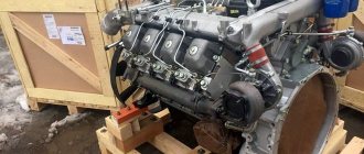
MAZ wiper motor pinout
Cars are equipped with a windshield wiper with three blades for cleaning windshields.
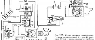
The windshield wiper is turned on by switch 1 (Fig. 1), which has three positions:
“Off”, “Low speed on”, “High speed on”.
When the first (low speed) is turned on, contacts “L” and “V” are turned on, as well as “D” and “I” of switch 1.
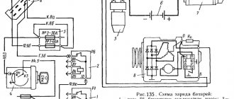
Voltage is supplied through the gray wire to the thermobimetallic fuse 10 and from it to the fixed contact 8. Then the current flows to the plug block and from it through the white wire to the “L” terminal of the switch.
From the “L” terminal, the current flows to the “V” terminal, through the yellow wire to the “D” terminal, and through the plug block to the positive electric brush of the motor armature.
Having passed through the armature, the operating current flows to fixed contact 7 and from it through the plug block through the black wire it goes to ground.
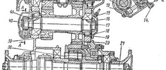
From the interaction of the magnetic fields of the permanent magnet 5 and the magnetic field of the armature, the latter begins to rotate. At the same time, cam 9 mounted on the worm gear of the windshield wiper gear rotates, closing and opening contacts 6, 7 and 8.
When the second, increased speed is turned on, the contacts of terminals “L” and “H” of switch 1 are closed, the contacts of terminals “D” and “I” are opened, the operating current no longer flows to the positive terminal of the armature, but through the brown wire to the additional electric brush, which leads to to a decrease in the working turns of the armature and, consequently, to a decrease in the magnetic field of the armature, as a result of which the frequency of rotation of the armature increases.
When the windshield wiper is turned off, the circuit of terminals “L” and V” of switch 1 is broken, but armature 4 of the electric motor continues to rotate, since power is supplied to it through closed contacts 6 and 8 to the plug block, from it through the red wire to switch 1, through it - to terminal “D”, from which the current passes through the yellow wire to the positive electric brush of the armature, through the armature to the negative brush, to pin 7 and from it to ground.
The armature rotates until cam 9 opens contacts 6 and 8. This position of the cam corresponds to the placement of the windshield wiper blades at the bottom of the car windshield.
Due to the inertia of the armature, the latter can make several more revolutions before stopping, which will lead to the brushes moving up the windshield, which will interfere with the driver.
In order to eliminate this phenomenon, contact 7 was introduced, when closed with contact 6, the armature electric brushes are bypassed between each other, which is easy to trace in the diagram.
When shunting, an abrupt stop of the armature occurs, which ensures that the brushes are laid strictly in the specified position.
The heating and ventilation system of the cabin has two electric motors, which are switched on at low and high speeds, which changes the performance of the fans.
In the first position of switch 11, both electric motors operate at high speed, since they are connected in parallel. In the second position, both electric motors are connected in series.
Functionality check
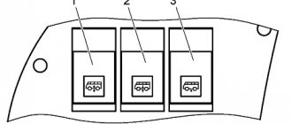
On the body of each relay there is a diagram with contact numbers and control voltage rating. A rectangle with pins 85 and 86 means a coil. Therefore, when measuring winding parameters, you need to connect to them. Other pins numbered 30, 87 and 87a (88) are the switching key for the external circuit.
It is convenient to use a digital multimeter as a tester for regulator relays and any other electromagnetic relay. This is because it can measure current, voltage and resistance.
Since the performance of the device depends primarily on the health of the winding, the test begins with measuring the coil resistance. Its values range from several tens of ohms to several hundred ohms.
To do this, switch the multimeter to resistance measurement mode. We connect measuring probes to pins 85, 86 and take readings. If the resistance is within normal limits, then you need to check the condition of the controlled outputs. In a relay with normally closed contacts 30 and 87, when measuring the resistance between them, the multimeter should show 0 Ohm. With normally open pins 30 and 87 the resistance between them should be infinity. When the control voltage is applied to the coil terminals 85 and 86, everything should change exactly the opposite.
Sometimes only the actuation current is known, then the coil resistance is measured. After this, the multimeter readings are multiplied by the operating current, and the control action of the winding is obtained. Then, by applying the calculated voltage, you can check the contact group, as described above.
Only AC voltage can be applied to the AC relay coil.
After checking the relay, if there is a need and the ability to adjust the contacts, do so. Otherwise, replace the entire device. Its installation and removal must be carried out with the device's power turned off.
Scheme of operation of the MAZ windshield wiper and brushes
The windshield wiper circuit is similar to the MAZ heater circuit.
When low speed is turned on, contacts V and L are activated, modes D and I are set on the first switch.
To the thermo-metallic fuse 10, and then to the fixed contact.
Current then flows to the switch terminal L.
From this terminal, the voltage is transferred to terminal V, then to D. The final point of current transfer is the plug block to the electric armature brush of the MAZ electric motor.
Also in MAZ windshield wipers, the operating current affects:
- Contact 7 (fixed type);
- Magnets;
- Anchor;
- Cams;
- Reducer gear;
- Contacts 6,8, 7.
AUTOMOTIVE ELECTRICAL DIAGRAMS
To download a diagram, you need to click on it with the mouse, then on the arrow below “full size” and right-click on “save drawing as...”.
Electrical connection diagram for the chassis of MAZ cars -631705
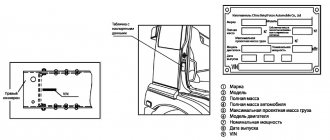
List of electrical equipment elements on the diagrams of the MAZ-631705 Al car - Fuse and relay block A3 - Windshield wiper breaker A6 - Turn signal breaker A7 - Radio tape recorder A8 - Range locking relay BAI, BA2 - Loudspeaker VK - Temperature sensor VR1.VR2 - Air pressure sensor VRZ - Oil pressure sensor BP4.BP5 - Emergency air pressure sensor BPI0 - Emergency oil pressure sensor BV2 - Speedometer sensor BV3 - Speed sensor EKZ, EK4 - Spark plug EFU E1, E2 - Headlight EZ, E4 - Fog light E5, E6 - Front light E7 — Lantern E8 — License plate lamp E9…E11 — Road train sign lamp EI2 — Underbody lamp
E13,E14 — Side turn signal EI5.EI6 — Position light E17, E18 — Rear light E20 — Reversing light E23.E24 — Cabin light E25 — Engine light E26 — Headlight — spotlight E28, E27 — Bed light EK1 ,EK2 - Shelving light EZO - Mirror heater EL1...EL6 - Instrument backlight lamp FU1 - Fuse 60 A FU2 - Fuse 30 A FU3-FU9 - Fuse 8 A FU11 - Fuse 16 A G - Generator GBl, GB2 - Battery 6CT I90A HA 1 - Set of electrical signals HA2 - Pneumatic signal KK1 - Additional resistance KK2 - Parking brake warning lamp breaker K1 - Starter relay Ml - Starter M2, MZ - Heater motor M4 - Wiper gear motor M8 - Washer motor RR - Instrument cluster P2 - Tachometer PS — Speedometer RP — Backlight rheostat XSl — Main socket XS3 — Socket XS4 — Portable lamp socket in the cabin XS5, XS6 — Socket WA — Antenna SA1 — Starter switch SA2 — Wiper switch SA3 — Main light switch SA4 — Turn signal switch SA5 — Heater switch SA7 — Lamp switch SA8 — Lamp switch SB1, SB3 — Push-button switch SB4 — Hazard switch SA9 — Hydraulic extraction valve switch Push-button switches with backlight: SB5 — Fog lights SB8 — Neutral switch SB9 — Engine light SB11 — Finder headlight SB12 — Interwheel differential SB13 — Center differential SB 14 — Road train lights SB 15 — Heated mirrors SB20 — Shelving lights SK — Emergency temperature sensor SLI — Fuel level sensor SP1.SP6 — Stop signal switch SP7 — Switch SQ1, SQ2 — Switch Warning lamps: HG1 — Warning lamp block HG4 — Tractor turns HG5 — Trailer turns HG7 — ECU systems HG8 — High beam HG9 — Divider switches HG10 — Interaxle blocking HG11 — Cross-wheel locks HG12 — Neutral switches Electro-pneumatic valve: Y1 — Pneumatic signal Y2 — Fuel electric valve Y3, Y4, Y7 , H9 -Electromagnet Y5 -Electromagnet
Electrical connection diagram for the cabin of MAZ-631705 cars
Similar auto electrical circuits
- Electrical diagrams BMW 5 E39 (0)
- Electrical diagrams of Saab 9-5 from 1997. (0)
- Electrical wiring diagrams for “Priors” - VAZ-2170. (0)
- Electrical diagram of Volvo S40 - V40 cars (from 1996 to 2000) (0)
- Electrical diagram of UAZ - 469 and 3163-Patriot (0)
Installation of windshield wiper arms and brushes MAZ
As soon as the mechanism for quickly cleaning windshields for MAZ is started, the circuit consisting of terminals V and L immediately breaks.
At this time, the armature of the mechanism, according to the general scheme of MAZ windshield wipers, continues to rotate.
However, as soon as cam 9 opens contacts 8 and 9, the wiper blades are placed at the bottom of the glass.
The ventilation and heating system includes electric motors. The mechanisms operate at both low and high speeds.
Checking the starter regulator
To check the starter regulator relay without removing it from the car, you can use a multimeter and test all the wires that go to it. To do this, they are first disconnected from the regulator. The multimeter is switched to resistance measurement mode, the disconnected wires are checked.
If everything is normal, then the conductors are returned to their place. The voltage at the battery terminals is measured with the engine off. The multimeter is switched to DC voltage measurement mode in the range from 0 to 20 Volts. The probes attach to the battery terminals. The device should show 12.2-12.7 V. If 12 volts or lower, then it needs to be recharged.
Then the engine must be started and checked again with the same measurements. If the voltage is in the range of 13.2-14 V, then this is normal. We add engine speed to 2000 per minute and measure again. Normally, the multimeter should show between 13.6-14.2 V. We also add revolutions to 3500 per minute.
We take readings. They should not exceed 14.5 Volts. If the value does not change and remains 12.7 Volts, as when the engine is turned off, or even decreases, then the regulator relay is faulty. Therefore it needs to be replaced. If 14.5 Volts are exceeded, the regulator must also be changed.
Sometimes the question arises of how to test a relay with a multimeter if there is no access to the regulator. Then you need to remove it, and to check it you must have, in addition to the tester, a charger with a voltage regulator and a light bulb. The following scheme is assembled from them. The charger is connected to the input terminals of the regulator, and the light bulb is connected to the output (thick) terminals. A multimeter monitors the voltage at the regulator input. By charging we change the voltage from 12 to 15 volts. The light should go out at 14.5 volts. If this does not happen, the regulator is faulty and must be replaced.
Maintenance of MAZ windshield wipers
During scheduled maintenance, the electric motors of all systems are not checked.
If you experience malfunctions in the operation of your windshield wipers, we recommend:
- Inspect fuse 12 and 10, switch 1. The mechanisms must be in good working order.
- Make sure there is voltage at the connector terminal.
- If you notice that one of the parts needs to be repaired, remove the MAZ windshield wiper for more convenient repair of the mechanisms.
- In the picture you will see possible malfunctions of MAZ brushes and solutions.
We repair MAZ windshield wipers
Once you have disassembled the unit, carefully inspect for any faults:
- Anchor;
- Contacts;
- Electric brushes;
- Worm gear reducer.
In most cases, you will notice the following malfunctions in the operation of the MAZ windshield wiper circuit:
- The teeth of the wheel are very worn - we replace the wheel with a new spare part.
- There are traces of carbon on the contacts - the stop contacts must be cleaned.
- All electric brushes on the car must be replaced with new ones if they are severely damaged.
- If damaged, the armature is carefully ground and the surface of the truck commutator is also ground.
After a step-by-step repair of reliable MAZ windshield wipers, we recommend installing all the parts so that the lever system is visually pulled into one line.
In more detail, you can study the windshield wiper diagram for MAZ in the figure (see above).
Be sure to follow this rule, otherwise the windshield wiper will quickly fail.
Source
Operating principle
Essentially, a relay is an electromagnet. When control voltage is applied to the coil, the rod attracts the armature, thus switching the circuit.
There are three types of relays:
- with normally closed contacts;
- with normally open;
- throwing over.
When a control signal is applied to a device with normally closed connectors, they open; if there is no signal, they close. For relays with open connectors, the opposite is true. There is voltage on the winding, the terminals close, but when there is no voltage, it opens. In flip-over models there are two sets of connectors, one normally closed and the other normally open. They have a common terminal. When current is applied to the winding, the contacts switch from one position to another.
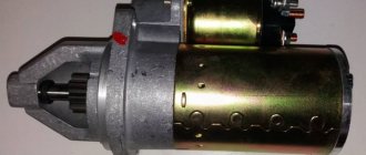
Checking the solenoid relay
When the battery is charged, but the engine does not start, you need to check the starter.
If the generator spins but the engine does not, then in such cases it is necessary to check the solenoid relay of the electric motor and the bendix. To do this, you need to remove the starter. After this, all contacts are cleaned, and the resistance of the relay winding is measured with a multimeter. If the value is infinity, then the winding has burned out. In this case, it is necessary to rewind the coil or replace it. The device shows several tens of ohms, which means the winding is intact.
Then its performance is checked. The positive terminal of the battery is connected to the corresponding relay terminal using the cigarette lighter. And the minus is connected to the starter housing. A click should be heard, then the device is working properly, otherwise it needs to be disassembled and the mechanical part checked.