GAZ Gazelle Business Logbook Replacing the electric motor of the GAZelle business stove
In general, the stove had been asking for a long time, howled on the waves, squealed on the bumps, and then one day it started howling all the time... it was decided to change it myself (the toad would strangle 7 thousand to give for a replacement) plus make a noise on the engine shield... I decided to try to film the whole thing, climbing a bunch of videos and I couldn’t find any data on the forums. The biggest problem was that it was very difficult to find a garage for such a crocodile, so having stocked up on a 220V heater, I went to open it with spare parts to replace the stove motor... I also bought: 4 sheets of STP AERO PREMIUM (2.5 was enough)2 sheet BIPLAST A 15 (1.5 was enough)
READ VAZ 2107 generator does not charge
Below are pictures with the positions of the bolts! Attention, you will need to remove: - Brand from the battery - side racks - plastic with places for standard speakers - side panel covers - dashboard - middle part (xs as the name) between 4.5 and 6.7 - lower glove compartment—right cup holder—pry off the plastic under the windshield with a screwdriver (I don’t know what it’s called)…
If everything worked out, move on, open the hood and look
We unscrewed it, we go into the salon, the panel should be loose. You need to unscrew the heater radiator pipes in the salon
How to remove the instrument panel on a Next gazelle
Swapers experience approximately the same sensations when encountering similar products for the first time. So I thought, what should I do on Friday evening? Maybe move the arrows?
To revive such a device, you either need to have your own motor brains as a source of a digital signal (although you will most likely sell them to another lucky gazelle driver along with the wonderful engine of the “Kamen” system), or something that replaces these brains (issuing the same commands) . Or you can replace the tidy with some old one. Each option undoubtedly has its pros and cons.
In the following videos, the computer with the mouse will be replaced with a box - a data converter from the Toyota digital bus format to the Gazelle bus. After which we will proceed to the tidy of Ford and VW.
Thanks to Misha and Denis for the equipment provided to be torn apart, you are the best =) I hope that pre-production mock-ups of the future device can be tested this year. The device, as usual, will be universal, i.e. will be suitable for any car with a digital dashboard (CAN or MPX/BEAN)
Installation diagram of the Starline B94 car alarm on a GAZelle-Next car from 2012
Car alarm Starline B94 - alarm with auto engine start, control range 2000 meters
Remove the GAZelle Next instrument panel. To do this, dismantle the torpedo, then unscrew the 4 screws and remove the steering casing. We remove the instrument panel cover and, having unscrewed the 4 fastening screws, remove the instrument panel itself
We install the alarm unit behind the instrument panel
We connect the alarm ground behind the instrument panel
In the connector of the instrument panel we connect the handbrake control according to diagram 1, the door limit switches according to diagram 2 and the alarm system.
Repair of the GAZelle Next instrument panel. (surge suppressors)
Programmable function Function meaning
9.starter cranking duration 6.0 seconds
Setting up the shock and tilt sensor. We check the operation of the alarm. We assemble the GAZelle Next interior in the reverse order.
The instrument panel consists of a metal support frame, a plastic frame and removable parts.
The plastic frame is attached to the metal frame with thirteen breakaway rivets.
The assembled frame is attached to the cab panels with screws and plastic holders.
Disconnect the negative terminal of the battery
Disconnect the positive terminal of the battery
In the engine compartment, unscrew the coupling bolt of the terminal connection of the upper and lower intermediate shafts and disconnect the intermediate steering shaft
We pull the edges of the two recesses in the lower decorative shield and, overcoming the resistance of the latches, remove the shield, disengaging its axes from the hinge axes
We remove the axes of the box from engagement with the axes of the hinges and remove the box
Unscrew the two screws on the left securing the lower cladding
Unscrew the two screws on the right securing the lower cladding
Pull the edges and disengage from the panel, first the two spring holders located on the sides of the cladding, then the latches located on top and remove the cladding
We remove the steering wheel, having first installed the wheels straight.
Remove the steering column cover. Remove the steering column switch assembly
how to remove the instrument panel on Gazelle Next
Disconnect the wiring harness of the instrument switch and ignition switch
Under the instrument panel, unscrew the two bolts securing the ball joint of the upper intermediate shaft
READ Replacing fuel filter ssangyong actyon diesel
Unscrew the two bolts securing the steering column to the instrument panel frame on the left
Unscrew the two steering column mounting bolts on the right and remove the steering column
We disconnect the connectors of the wiring harnesses located under the instrument panel
Press the latch and disconnect the wire block from the fan motor
Disconnect the wire block from the additional resistor
We unscrew the fastening bolt and disconnect the panel frame support from the cab bracket.
We take out the plug in the upper central part of the instrument panel (near the windshield) and unscrew the bolt securing the panel to the front panel bracket.
We remove the plugs and unscrew the two bolts on the left securing the panel frame to the cab pillar
We unscrew the two bolts on the right securing the panel frame to the cab pillar
We lift the instrument panel up by six to eight mm, removing the side hooks of the panel from engagement with the rectangular holes in the front pillars of the cabin.
Pull the instrument panel back, disengage the mounting tabs of the panel from engagement with the front panel and remove the panel.
Install the instrument panel in reverse order.
How to Disassemble a Panel on a Gazelle ~ AUTOINTERLINE.RU
Many drivers, paying tribute to fashion, want to replace the old device panel on a Gazelle car with a panel of a new standard. The article is devoted to the “Gazelle tidy”: purpose, probable malfunctions. Annotation is given on the removal and installation of the torpedo.
Panel purpose
The main purpose of the device panel is to inform the driver about the current state of the car. On the Gazelle, all instruments and indicators are located on a small section of the torpedo. Drivers get used to this arrangement of devices.
The device panel of the old standard on the Gazelle contains from 3 to 5 round dials, which are surrounded by various indicators. The largest dials are the tachometer and speedometer. The main device is the speedometer, which is why it is always located in the center.
The third largest device is the cooling water thermometer. In addition, on the dashboard there are dials for charging the battery and the amount of gasoline. The oil dial is located less frequently.
Tidying up the old standard
Updated look
Drivers are replacing their old dashboard with a business panel because of its attractive appearance. The second prerequisite for the change will be that the Gazelle Business device panel has expanded functionality and more abilities to provide information about the operation of the car.
The Euro panel is equipped with 2 large dials for the speedometer and tachometer and 2 small ones, informing about the amount of gasoline and coolant temperature. Other indicators are placed in the center.
The simplicity of the Euro panel makes it easier for the driver to receive information. The downside of the newest panel is the difficulty of installation. True, the pinout is contained in the annotation. If the car owner has experience in similar work, then it will not be difficult for him to install the latest tidy.
Pinout of the Gazelle device composition
Functional
If the installation is completed correctly, then the new composition of devices works properly. The only drawback is the weak backlight, which is practically invisible at night. It is recommended to install LED backlighting of devices along the entire perimeter of the panel (video creator - Vodila Chelyabinsk).
The Gazelle is equipped with 20 indicators that indicate that one of the vehicle’s components or sensors is not working.
If the “Stop” light comes on along with one of the icons, it is better to remove the problem before starting to drive.
Using indicators, the dashboard displays information about the status of the main components and assemblies of the vehicle. A detailed description of the purpose of each of them can be found in the instructions for installation and operation.
Typical faults
After changing the device, the following malfunctions are likely:
- either some of the devices or the entire panel does not work;
- the arrows on the devices stop;
- incorrect sensor readings.
You can solve the problem by following these steps:
- First you need to check the power supply: integrity of wires, quality of contacts.
- If everything is fine with the wiring, the controller may be broken. It is better to replace the entire panel than to repair the controller.
- The sensors may not work if the contact is poor or the fuse is blown.
- You can test the operation of the sensors again by pressing the “Mode” button.
When changing the composition of devices, the electronics are not affected, but problems occur specifically with them. The problem is solved by changing fuses and updating the wiring.
Typical faults
After replacing the device, the following malfunctions are possible:
- either part of the instruments or the entire panel does not work;
- the arrows on the instruments stop;
- incorrect sensor readings.
Read:
You can solve the problem by doing the following:
- First you need to check the power: the integrity of the wires, the quality of the contacts.
- If everything is fine with the wiring, it is possible that the controller is broken. It is better to replace the entire panel than to repair the controller.
- The sensors may not work if the connection is poor or the fuse is blown.
- You can try to restore the operation of the sensors by pressing the “Mode” button.
When replacing the instrument cluster, the electronics are not affected, but problems occur with them. The problem is solved by replacing the fuses and updating the wiring.
Panel purpose
The main purpose of the instrument panel is to inform the driver about the current state of the car. On the Gazelle, all instruments and indicators are located on a small area of the torpedo. Drivers get used to this arrangement of instruments.
The old-style instrument panel on the Gazelle contains from 3 to 5 round dials, which are surrounded by different indicators. The largest dials are the tachometer and speedometer. The main instrument is the speedometer, so it is always located in the center.
The third largest device is the coolant temperature gauge. In addition, the dashboard contains dials for charging the battery and the amount of gasoline. Less commonly, an oil dial is present.
Old style tidy
How to remove and install the instrument cluster of a Gazelle car
Three instrument combinations can be installed on GAZelle family cars of different years of production and configurations: the old model produced before 2003, the new model produced since 2003 for cars with engines ZMZ-4063, ZMZ-40522, UMZ-4215 and the new model produced since 2003 for cars with ZMZ-40524 and UMZ-4218 engines.
The instrument cluster combines all the vehicle's instrumentation.
It includes a speedometer, total and daily mileage counters (in combinations of the old model produced before 2003 and the new model produced since 2003 for cars with engines ZMZ-4963 ZMZ-40522 and UM Z-4215 mechanical type counters
And in the combination of a new model produced since 2003 for cars with ZMZ-40524 and UMZ-4218 engines, meters are located on the first liquid crystal display), an electronic tachometer (from 0 to 6000 rpm), a clock and a voltmeter on the second liquid crystal display (in combination new model produced since 2003 for cars with ZMZ-40524 and UMZ-4218 engines), coolant temperature indicator, fuel level indicator, control and warning lamps, backlight lamps.
Temperature and fuel level indicators of electromagnetic type.
The instrument cluster of a new model produced since 2003 for cars with ZMZ-40524 and UMZ-4218 engines provides an audible alarm function in the event of an emergency.
In addition, it uses “night” and “day” backlight modes for liquid crystal displays for easy viewing of readings
The developers of the instrument cluster have also introduced a self-testing mode, which allows you to monitor the proper operation of the pointer indicators, the display of information on liquid crystal displays, and the functionality of the alarms.
GAZ Gazelle business 4x4 Titan - pinout
1 - not connected 2 - 382.3801 has an open door alarm (may not be present). You can run a wire to the limit switch on the driver's door. 3 - 382.3801 has an oil overheating indicator (may not be present). You can run a wire to the TM-108 overheating sensor, and put the sensor itself into the crankcase. 4 - 385.3801 has an open door alarm (may not have one). You can run a wire to the limit switch on the driver's door. 5 - 382.3801 has a test. If ground is applied to this contact, the indicators for brake fluid level, oil overheating, open doors and coolant overheating light up. Can be connected to a button or relay. In the second case, the relay winding is connected to ground and the wire from the lock to the starter (i.e., when the starter is turned on, the lamps will be tested). 6 - 382.3801 has a seat belt warning indicator (may not be present). 7 - 382.3801 has a fuel reserve indicator. Connect the blue wire with the red stripe. 8 — fuel level indicator. Connect to the pink wire with the red stripe. 9 — oil pressure indicator. At 382.3801, run a wire to the sensor (you need a VAZ-2106 tee) from GAZ under the ZMZ-406 engine. With 385.3801, if you install a sensor, it will squeak about low pressure at idle, so a sensor is not needed, you need to connect the wire from the device to ground through a resistor, select it experimentally. 10 — emergency oil pressure indicator. Connect to the gray wire with a blue stripe. 11 — engine overheat indicator. Can be connected to overheat sensor TM-111-02. The sensor itself must be in contact with the coolant. 12 — coolant temperature indicator. Connect to the green wire with a white stripe. The pointer will exaggerate the readings; you can connect a resistor to the wire gap and select it experimentally. 13 - indicator for closing the carburetor air damper. Connect to the gray wire with an orange stripe if the car is a carb. 14 - for 382.3801 the indicator may be on and will light up when the mass is supplied. 15 - downshift indicator (may not be present), will light up when the mass is supplied. 16 - differential lock indicator (may not be present), will light up when the mass is supplied. 17 - for 382.3801, the seat heating indicator will light up when positive is applied. 18 - rear PTF indicator (may not be present), lights up when positive is applied. 19 — side light indicator. Connect to the yellow wire. 20 — instrument lighting lamps. Connect to the white wire. 21 - 385.3801 has power supply to the meter. Connect to constant power (red-white wire of stop switch). 22 and 23 - right and left turn signal indicators, respectively. You can connect them together and connect to a blue wire with a white stripe (the arrows will light up when the left or right turn signal is turned on), or to the hazard warning switch: blue - right, blue-black - left, insulate the blue wire with a white stripe (each arrow will correspond to the activation of its turn signal). 24 - parking brake indicator. Connect to the brown wire. 25 - high beam headlight indicator. Connect to the green wire with a black stripe. 26 - front PTF indicator (may not be present), lights up when positive is applied. 27 - ABS indicator. When the mass is supplied it will light up. 28 - 385.3801 has a rear window heating indicator. Lights up when positive is applied. 29 — speed signal output to the on-board computer. If it is, then take the speed signal from this contact. 30 - to the vehicle speed sensor. 31 - low brake fluid level indicator. Connect to the pink wire with a blue stripe that goes to the lamp above the cigarette lighter. 32 - power supply for lamps and devices. Connect to the orange wire with the blue stripe. 33 - battery charge indicator. Connect to the brown wire with a white stripe. 34 - mass. Connect to the black wire. Wow, I wrote a lot... 35 — speedometer power supply. Connect to the orange wire. 36 — speedometer mass. Connect to the white wire with a black stripe. 37 - tachometer. Connect to the brown wire with a blue stripe, but if the readings drop, connect to pin 38. 39 - 385.3801 has a low beam indicator (it may not be present), it will light up when positive is applied. 40 - low oil level indicator (may not be present), will light up when the mass is supplied. 41 - if the car is injection, connect to the orange wire too. 42 - if the car is injection, connect to the remaining wire (I don’t know the color) it went to the 8-terminal block on the old device. 43 - brake pad wear indicator (may not be present), will light up when the mass is supplied. 44 - glow plug indicator. 45 and 46 - does not connect. 47 - low coolant level indicator (may not be present), will light up when the mass is supplied. 48 - low washer fluid level indicator (may not be present), will light up when mass is supplied. 49 - low power steering oil level indicator (may not be present), will light up when the mass is supplied. 50 - the indicator for burnt out lamps on 382.3801 or the presence of water in the fuel filter on 385.3801 (may not be present) will light up when the mass is supplied. 51 and 52 - 382.3801 has indicators (may not be present) that will light up when the mass is supplied.
Diagram and contacts of the Gazelle instrument cluster
XP1 connector
1 Coolant temperature sensor 2 Emergency coolant temperature selection 3 Emergency low engine oil pressure 4 Oil pressure sensor 5 Fuel level sensor 6 ———- 7 ———- 8 Open bus doors 9 ———- 10 Open interior doors, hood or trunk 11 ——— 12 ——— 13 Malfunction of the electronic brake force control (EBD)
XP2 connector
1 Battery 2 Right side turn signal lamps on 3 Left side turn signal lamps on 4 Parking brake on 5 High beams on 6 Front fog lights on 7 Gearbox illumination 8 Side lights on 9 Rear fog lights on 10 ——— 11 Center differential lock on 12 Downshift 13 Type of oil pressure sensor
XP3 connector
1 Housing for analog signals 2 Ignition 3 Housing 4 High-voltage tachometer input 5 Low-voltage tachometer input 6 Low beam headlights on 7 Low battery 8 Ignition 9 Low brake fluid level 10 Speed sensor 11 Speedometer output to on-board computer 12 Heated rear window on 13 Anti-lock brake malfunction brake systems (ABS)
XP4 connector
1 Diagnostic indicator (-) 2 Diagnostic indicator (+) and activation of engine preheating (+) 3 Wear of brake linings 4 Activation of engine preheating (-) 5 ————- 6 ————- 7 ————- 8 ————- 9 ————— 10 ————- 11 Windshield washer fluid level low 12 Coolant level low 13 Engine oil level low
Detailed description of icons
Details about instrument combinations, decoding of symbols and pictograms are described in the GAZelle operating instructions.
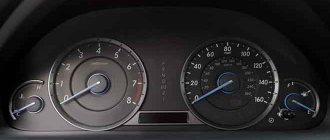
The panel is a combination of instruments with sound and signal indication. The main meters that the driver focuses on are the speedometer and tachometer, located on either side of the signal sensors. The speedometer indicates the speed of the vehicle. Its scale ranges from 0 to 200 km/h. The tachometer shows the crankshaft rotation speed of the power unit per minute with a scale of 0-6.
On the left side of the speedometer there is a device that determines the amount of fuel in the fuel tank. Nearby is the “Reset” button, when clicked, the daily mileage readings are reset to zero. Mileage parameters can be read on the digital odometer, with the upper numbers indicating the total value, the lower ones indicating the daily value.
To the right of the tachometer is the coolant temperature indicator. The arrow moving into the red sector means the engine is overheating. The motor runs until the alarm high temperature signal is triggered.
In the lower right corner there is a “Mode” button that turns on the ignition. Signal sensors are installed in the center of the panel.
Flashing red:
- STOP indicator, when activated, further movement is prohibited until the problems in the car are resolved;
- indicator of lack of battery charging, which operates when the ignition is turned on until the engine starts;
- indicator of low oil pressure in the engine;
- minimum fluid level sensor in the brake system hydraulic drive reservoir;
- engaging the parking brake.
Instrument cluster
Tachometer. Indicates the engine speed in rpm. Do not allow the engine to run for long periods of time at speeds above 3600 rpm.
Engine coolant temperature gauge. When the arrow reaches the red zone of the scale and the emergency high coolant temperature indicator lights up, it is necessary to stop the engine and eliminate the cause of overheating.
Mode/trip computer control button.
To self-test the instrument cluster, turn on the instruments (key position I) and after 1–2 seconds press the button. In this case, indicators 2, 3, 4, 7, 9, 11, 24, 26, 27, 29 and 30 are turned on, all segments of the multifunction display, dial indicators go from minimum to maximum.
The self-test mode is interrupted: independently after the instrument needles move from the initial scale mark to the maximum; when the engine crankshaft speed signal appears, when the instruments are turned off.
After the self-test mode ends, the instrument cluster enters operating mode.
To control the trip computer (menu selection in a circle), turn the button clockwise (MK-up) or counterclockwise (MK-down).
Multifunction trip computer display. See operating modes on the next page.
Button for setting daily mileage readings to zero/changing hours and minutes.
To reset the daily mileage reading to zero, press the button and hold it pressed for at least 3 seconds.
To change the hours and minutes, turn the button: clockwise to change the hours, counterclockwise to change the minutes.
Fuel level indicator.
The fuel tank can hold up to 64 liters of fuel. When the remaining fuel is less than 8 liters, the needle reaches the red zone of the scale and the indicator for the minimum fuel reserve in the tank lights up.
Speedometer. Indicates the vehicle speed in km/h.
ATTENTION!
To avoid malfunctions in the operation of the instrument cluster, it is prohibited to disconnect the battery (disconnect the wires from the terminals, etc.) while the instruments are turned on.
To eliminate the consequences of malfunctions in the instrument cluster:
- Turn off appliances.
- Restore the connection between the battery and the vehicle's on-board network.
- Press and hold the Mode button and turn on the devices. In this case, the dial indicators will return to their original position.
Replacing the old instrument cluster with a new one
Many car owners of a gazelle or Volga car with an old-style instrument panel strive to change it to a new-style instrument panel, in which most of the indicators have been replaced with modern LED ones, and such an instrument panel looks much prettier and brighter.
So, to remove the instrument cluster, first remove the trim by unscrewing the four screws. Then remove the four screws securing the combination; disconnect the electrical connectors and remove the instrument cluster. Repair the instrument cluster by block replacement of faulty devices. To replace devices, remove the protective glass and unscrew the nuts securing the faulty device on the reverse side.
The reason why many drivers install the Gazelle Business dashboard is because it looks better. The second reason why you should buy this particular panel option is the functionality and increased number of opportunities to monitor the performance of the car.
The euro-type panel has 2 large dials - speedometer and tachometer, as well as 2 small ones, which display the amount of gasoline and the temperature of the coolant. The rest of the information about the state of the nodes and any errors that have occurred is displayed using illuminated indicators in the middle of the panel. A simpler design significantly relieves the driver’s attention.
Dashboards for Gazelle
Is it worth installing a new Gazelle instrument panel in the car, or is the old panel quite suitable for use? The question is quite common, especially among those drivers who have had the opportunity to slightly update their car. It’s worth installing a new thing, but how much it will cost is another question.
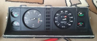
Classic Gazelle dashboard
Panel purpose
The instrument panel performs one function - informational. In a small area in the dashboard of the car, all the instruments with indicators about the car’s performance are located, this is both good and not very good. While the driver is looking for the indicator, the speed indicator, he is distracted from the road, creating conditions for an emergency situation. However, most Gazelle users eventually get used to the appearance of the panel and intuitively examine one or another section of it to obtain information.
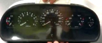
The standard panel on most modifications of the Gazelle looks like 3-5 round dials surrounded by several signaling devices. The main gauges—the speedometer and tachometer—are large.
The speedometer is always located in the center, since it is the main device that the driver focuses on. The three largest devices most often include the coolant temperature sensor. The remaining dials indicate either the amount of gasoline, or the battery charge, and less often, the amount of oil. All the indicators that the driver needs can also look like warning lights. Their indicators light up from time to time. The devices are placed compactly and do not interfere with each other.
Appearance of the update
The reason why many drivers install a Gazelle business dashboard is simple - it looks better. The second reason why you should buy this particular panel option is the functionality and increased number of opportunities to monitor the performance of the car.
Gazelle business dashboard design
The disadvantage of such a panel is that on most Gazelles you will have to sweat a little when connecting. The device's pinout diagram is included in the kit, so there will be problems with the connection if you have not encountered such work before. You will also have to add several terminals and change several contacts so that all devices and sensors work correctly.
Functional
In most cases, everything works properly without the slightest breakdown, but the new panel can still be improved. Many people do not like the dim illumination of devices, which is practically useless at night. It is recommended to install LED lighting and diodes inside the devices and around the entire perimeter of the panel for better visual perception. The new Gazelle instrument panel has almost 20 indicators that light up when a malfunction occurs.
4 of them, which indicate the level of emergency oil pressure, overheating of the coolant, emergency amount of fluid in the brakes and the parking brake sensor, may indicate serious damage to the system.
If one of the mentioned indicators lights up along with the STOP button, it is recommended not to start driving until the damage has been repaired.
In addition, the dashboard has various alarms about the lighting system, brakes and engine status. The driver has access to the most complete information about all the main components of the car.
Installing and removing the torpedo
The dashboard is included in the Euro kit for Gazelle. On the latest versions it is installed at the factory. Drivers of older models also want to upgrade their dashboard. Replacing the device is not difficult: the design of the fasteners is almost identical, and the panel seat is the same in size.
Replacing a torpedo entails significant alterations, since it differs in both the shape and design of the fastenings. The car owner has to think about what changes to make himself. Sometimes, to repair the stove, you have to completely dismantle the torpedo. To do this, you need to know how to remove and install the torpedo back. For this procedure you need to prepare a set of keys and screwdrivers. An assistant may be needed.
Removing a torpedo on a Gazelle
The removal procedure consists of the following steps:
- Before starting work, for safety reasons, the vehicle should be de-energized. To do this, you need to remove the negative terminal from the battery.
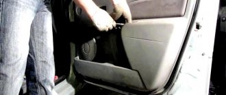
- First of all, all the pads are removed. Use a Phillips screwdriver to unscrew the screws securing the upholstery.
- Then, by unscrewing two screws, remove the casing from the steering column.
- Next, remove the trim from the instrument panel, remove it by pulling the steering wheel towards you until it stops.
- We unscrew the fastenings of the instrument cluster and dismantle the tidy, disconnecting all the wires.
- Next, remove the steering column along with all connections.
- At the next stage, turn off the power supply to the lighting: rear fog lights, interior lighting. You also need to turn off the electric headlight leveler.
- Then unscrew the air damper bolt.
- Disconnect the cable from the carburetor by unscrewing the screw securing the cable sheath.
- Next, turn off the cigarette lighter and hazard warning lights.
- Using a screwdriver, unscrew the two bolts near the stove control.
- After unscrewing the 10 bolts securing the panel, carefully remove it from its mounting location.
- Now we disconnect the air ducts from the deflectors.
- Remove the carburetor damper.
- We dismantle the panel by disconnecting the hoses of the heater air ducts.
- Now you can remove the torpedo. It is better to do this with an assistant, as it is very heavy.
- Installation of the torpedo is carried out in the reverse order.
After installing a new torpedo, some indicators may not work due to incompatibility between the system and the new torpedo.
Whether to install a new dashboard on a Gazelle or not - that is the question
Many drivers, paying tribute to fashion, want to replace the old instrument panel on a Gazelle car with a new panel. The article is devoted to the “Gazelle tidy”: purpose, possible malfunctions. Instructions are given for removing and installing the torpedo.
The main purpose of the instrument panel is to inform the driver about the current state of the car. On the Gazelle, all instruments and indicators are located on a small area of the torpedo. Drivers get used to this arrangement of instruments.
The old-style instrument panel on the Gazelle contains from 3 to 5 round dials, which are surrounded by different indicators. The largest dials are the tachometer and speedometer. The main instrument is the speedometer, so it is always located in the center.
The third largest device is the coolant temperature gauge. In addition, the dashboard contains dials for charging the battery and the amount of gasoline. Less commonly, an oil dial is present.
Old style tidy
Updated look
Drivers are replacing their old dashboard with a business panel because of its attractive appearance. The second reason for the replacement is that the Gazelle Business dashboard has expanded functionality and more options for providing information about the operation of the car.
The Euro panel is equipped with two large dials for the speedometer and tachometer and two small ones, informing about the amount of gasoline and coolant temperature. The remaining indicators are located in the center.
The simplicity of the euro panel makes it easier for the driver to perceive information. The disadvantage of the new panel is the complexity of installation. True, the pinout is contained in the instructions. If a car enthusiast has experience in such work, then it will not be difficult for him to install a new device.
Guide to removing the instrument panel on GAZelle Business and description of icons
The GAZelle Business instrument panel is the main component of the car interior, located in the front part and designed to provide information about the current state of the car, the performance of mechanisms and systems. The installed special shield of a new type has been improved, modernized and belongs to the Euro-3 class. Compared to older models, it is more convenient, informative, practical and has a modern design.
How to remove a GAZelle Business panel
In order to dismantle the GAZelle Business panel, you need to disassemble this panel. To do this, remove the old shield, disconnect the steering wheel with a special tool, unscrew the decorative trim screws and fastening bolts.
In case of some breakdowns, not only the instrument panel is dismantled, but also the dashboard. Removal of the kit should be done with care to avoid any conflict with the electronics.
The torpedo is attached like this:
- after removing the shield, turn off the interior lighting, rear fog lights, and electric headlight range control;
- unscrew the torso of the air damper and disconnect it from the carburetor;
- turn off the hazard warning lights, cigarette lighter;
- unscrew the fasteners in the amount of 10 pieces and disconnect the air duct hoses from the deflectors;
- remove the damper from the carburetor;
- turn off the air ducts;
- remove the torpedo.
Installation is carried out in reverse order.
Purpose of elements on the GAZ instrument panel
1 — the voltmeter indicates the voltage in the on-board network of the GAZ car; 2 — warning lamp of the engine management system; 3 - reserve (or abs malfunction warning lamp on a Volga GAZ car equipped with an anti-lock brake system); 4 — “STOP” light display. Lights up simultaneously with one of the malfunction indicator lamps, if further movement with this malfunction is prohibited; 5 - indicator lamp for turning on the left turn signal. The lamp lights up simultaneously with the left turn indicators. If one of the indicator lamps malfunctions, the control lamp blinks at double frequency; 6 - warning lamp for emergency drop in brake fluid level. The lamp lights up when the fluid level drops (below the minimum allowable) in the brake master cylinder reservoir. As the brake pad linings wear, it is necessary to add brake fluid; 7 — odometer (total mileage counter); 8 — the speedometer indicates the speed of the car; 9 - indicator lamp for turning on the parking brake. The lamp lights up when the parking brake lever is raised and the ignition is on. 10 — control lamp for turning on the right turn signal. The lamp lights up simultaneously with the right turn indicators. If one of the indicator lamps malfunctions, the control lamp blinks at double frequency; 11 - reserve; 12— warning lamp for unfastened seat belts (installed on some Volga GAZ 31105 cars); — warning lamp for emergency drop in oil pressure in the engine lubrication system. The lamp should light up when the ignition is turned on and go out after starting the engine. If the light remains on after the engine has started, or comes on while the engine is running, stop the engine immediately and check the oil level. The level is normal - the engine is faulty. For a car with high mileage, the lamp may come on when the warm engine is idling; 14 — reserve (for installing additional warning lamps); 15 — fuel level indicator. The device shows the approximate amount of fuel in the tank. The scale has divisions: 0 - empty tank; 1/2 - half a tank; 1 - full tank: 16 - fuel reserve warning lamp. The lamp turns on when the remaining fuel in the tank is less than 8 liters; 17 — oil pressure indicator in the engine lubrication system allows you to assess the technical condition of the engine; 19 — control lamp for turning on heated seats (for GAZ 31105 vehicles with heated seats); 20 — coolant temperature gauge allows you to control the engine temperature; 21 — control lamp for turning on external lighting (side light); 22 - the coolant overheating warning lamp turns on when the coolant temperature rises above the permissible value; 23 - control lamp for turning on the high beam headlights. The lamp turns on when the high beam headlights are turned on; 24 — button for setting the daily mileage counter to zero. In order to reset the counter readings, you must press the button; 25 — car daily mileage counter. To reset the counter readings, you must press the zero setting button (pos. 24); 26 - tachometer. The device shows the engine speed; 27 - battery discharge warning lamp. The lamp should light up when the ignition is on, and go out after starting the engine. Illumination of the lamp while the engine is running may indicate a malfunction of the generator or its circuits.
Icons on the dashboard of GAZelle Next and Business
The Gazelle Business dashboard has an expanded list of icons relative to older models.
Original combinations of symbols allow you to timely detect and eliminate breakdowns in machine components.
GAZelle Business dashboard: description of icons
The dashboard of a car with a UMZ 4216 engine has 26 current status indicators. Lamps and devices are divided into three groups:
- notifying;
- indicator;
- warning.
The first category shows the actions or state of the system that require increased attention or caution from the driver. The second type contains a complete group of notifications. This includes headlight position indicators and turn signals.
The third on the list is a type of signal that is reflected in red and requires immediate intervention from the motorist. Serious breakdowns or problems with the machine are displayed here.
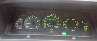
The photo shows the location of all elements of the 2016 Gazelle Business tidy.
Important! In versions 2010, 2012 and 2022, the location of the indicators and the design of the tidy itself may differ.
A complete decoding of combinations and decoding of icons describes the appearance and functional decoding.
- 1 – Fuel tank full indicator. The pointer element is based on a mechanical principle and rarely fails.
- 2 – Speedometer. The electronic part has a gradation of 20 km/h from 0 to 200.
- 3 – Handbrake operating position indicator. If the handbrake is raised, the element lights up red. The serviceability of the line is checked when the ignition is turned on - the lamp flickers. If the car starts moving, the indicator is duplicated by an additional sound signal.
- 4 – Battery health indicator. If the lamp ignites, there are problems with charging or the integrity of the battery is compromised. You need to check the generator wires and measure the voltage at the output terminals.
- 5/9 – turn signal indicators. It also indicates that the hazard warning system is activated. When switched on, they blink green.
- 6 – emergency oil pressure indicator. When the ignition is turned on, the light comes on - this indicates that the electrical line is working properly. When the engine reaches idle speed, the lamp goes out, which indicates that the required pressure has been built up. In some cases, the indicator begins to blink during a critical decrease in the crankshaft speed. When you let it go, everything becomes normal.
- 7 – STOP is located strictly in the center of the instrument and lights up simultaneously with some elements. The combination indicates that further use of the vehicle is strictly prohibited until the breakdown is repaired. A failure can be identified by the icon lighting up at the same time.
- 8 – ECM unit status indicator. The warning light is activated immediately after the ignition is turned on and does not go out for 7-8 seconds. If the sequence is followed, this indicates that the module is ready to start the engine. If the indicator periodically flashes while driving, one of the circuit elements has failed or there is an error in the electronic engine control system.
- 10 – indicator of the anti-lock brake system. When it is activated, the operation of the mechanism is disrupted. You can find out about the presence of a module in the vehicle's service manual.
- 11 – standard tachometer. The magnetic circuit is lined from 0 to 6 and indicates the actual speed of the crankshaft.
- 12 – the EBD option is installed on some vehicle modifications. Usually mounted in tandem with an ABS device. The indicator is displayed in the upper right corner. The ebd light says that the brakes are not working properly, the electronic force distribution is broken - requires immediate repair. If you continue to drive the car, the calipers may not work properly.
- 13 – indicator that the doors are closed correctly. If the car is moving with the locks open, the icon lights up and sounds a sound signal.
- 14 – the lamp is installed on a Cummins engine with a 4x4 drive and is responsible for indicating that the transfer clutch is engaged. Not used on vehicles version 3302 and similar.
- 15 – critical overheating lamp of the power unit. If an element is displayed on the dashboard, you need to stop immediately and turn off the engine. Continued use of the car until the antifreeze cools down is fraught with irreversible consequences for the car. In some situations, pipes rupture and the piston group jams.
- 16 – pointer indicator of the actual engine coolant temperature. Driving is allowed until the pointer moves into the red zone. The normal position is approximately in the middle of the scale in the green compartment.
- 17 – service key “mode” – installed on all modifications of cars.
- 18/22 – the light indicates that the rear/front fog lights are on. When the lighting is turned off, the indicator goes out.
- 19 – the indicator is intended to notify the driver about the inclusion of the high-range head lighting mode.
- 20 – indicator for turning on the headlights, located in the central part of the LCD display, paralleled by an audible alarm.
- 21 – indicator for turning on the low beam headlights.
- 23 – emergency loss of brake fluid volume in the expansion tank. When the indicator turns on, you must immediately stop and check the serviceability of the lines, eliminate leaks and replenish the tank.
- 24 – odometer. The lower part indicates the daily mileage, the upper part indicates the total mileage.
- 25 – reset key – using the control, the accumulated kilometers per day are reset to zero.
- 26 – fuel tank reserve lamp, lights up when most of the fuel is used up. The indicator lights up when there is no more than 8 liters of gasoline left in the fuel tank. It is prohibited to move in this mode for a long time - this may damage the pressure pump.
Removing the dashboard on a Gazelle
In general, the stove had been asking for a long time, howling on the waves, squealing on the bumps, and then one day it started howling all the time... it was decided to change it myself (the toad would strangle 7 thousand to give for a replacement) plus make a noise on the engine shield... I decided to try to film the whole thing, climbing a bunch of videos and I couldn't find any data on the forums. The biggest problem was that it was very difficult to find a garage for such a crocodile, so having stocked up on a 220V heater, I went to open it with spare parts to replace the stove motor... I also purchased: 4 sheets of STP AERO PREMIUM (2.5 was enough) 2 sheets of BIPLAST A 15 (1 was enough ,5)
Below are pictures of the bolt positions! Attention, you will need to remove: - Brand from the battery - side pillars - plastic sheets with places for standard speakers - side panel covers - dashboard - middle part (xs as the name) between 4.5 and 6.7 - lower glove compartment - right cup holder - pry off a plastic screwdriver under the windshield (what’s the name)…
If everything worked out, move on, open the hood and look
Unscrew it, go to the salon, the panel should be loose. You need to unscrew the heater radiator pipes in the salon.
Installing and removing the torpedo
The dashboard is included in the Euro kit for Gazelle. On the latest versions it is installed at the factory. Drivers of older models also want to upgrade their dashboard. Replacing the device is not difficult: the design of the fasteners is almost identical, and the panel seat is the same in size.
Replacing a torpedo entails significant alterations, since it differs in both the shape and design of the fastenings. The car owner has to think about what changes to make himself. Sometimes, to repair the stove, you have to completely dismantle the torpedo. To do this, you need to know how to remove and install the torpedo back. For this procedure you need to prepare a set of keys and screwdrivers. An assistant may be needed.
Removing a torpedo on a Gazelle
The removal procedure consists of the following steps:
- Before starting work, for safety reasons, the vehicle should be de-energized. To do this, you need to remove the negative terminal from the battery.
- First of all, all the pads are removed. Use a Phillips screwdriver to unscrew the screws securing the upholstery.
- Then, by unscrewing two screws, remove the casing from the steering column.
- Next, remove the trim from the instrument panel, remove it by pulling the steering wheel towards you until it stops.
- We unscrew the fastenings of the instrument cluster and dismantle the tidy, disconnecting all the wires.
- Next, remove the steering column along with all connections.
- At the next stage, turn off the power supply to the lighting: rear fog lights, interior lighting. You also need to turn off the electric headlight leveler.
- Then unscrew the air damper bolt.
- Disconnect the cable from the carburetor by unscrewing the screw securing the cable sheath.
- Next, turn off the cigarette lighter and hazard warning lights.
- Using a screwdriver, unscrew the two bolts near the stove control.
- After unscrewing the 10 bolts securing the panel, carefully remove it from its mounting location.
- Now we disconnect the air ducts from the deflectors.
- Remove the carburetor damper.
- We dismantle the panel by disconnecting the hoses of the heater air ducts.
- Now you can remove the torpedo. It is better to do this with an assistant, as it is very heavy.
- Installation of the torpedo is carried out in the reverse order.
After installing a new torpedo, some indicators may not work due to incompatibility between the system and the new torpedo.