Hello dear friends! In today's article, we will analyze and get acquainted with the brake system of the Gas 3307 truck. Gas 3307 is equipped with three brake systems: a working main one, acting on all wheels; a spare one is if, say, your rear brakes fail, the front ones remain in working condition, so - like the Gas 3307, the braking system is two-circuit: one circuit for the rear wheels and the second, respectively, for the front wheels.
And so, if one circuit fails, the second remains operational, that is, how a spare circuit turns out. And the third system: this is, of course, the parking (hand) brake. On older Gas 3307 models, the parking brake system has a mechanical drive that acts on the drum brake mechanism mounted on the gearbox. ( see Fig. 1. )
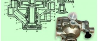
Fig.1. Parking brake Gas 3307, old model.
On new Gas 3307 models, they have already begun to install a parking brake that acts on the rear wheels. ( See Fig. 2. ) This design of a parking brake has been used on passenger cars for quite a long time. But on trucks not so long ago. I’m afraid of course I’ll be wrong, but I’ll say it anyway: they started installing such a parking brake system on Gas 3307 trucks around 2000. (But if I’m wrong, I apologize, I don’t remember exactly, but it’s not that important).
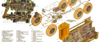
Fig.2. Hand (parking) brake Gas 3307, new model.
1. Lever; 2. Front cable; 3. Plug; 4. Adjustment screw; 5. Expansion link; 6. Support sleeve; 7. Drive lever; 8.9. Rear cables; 10. Equalizer lever; 11. Equalizer; 12. Bracket; 13. Adjusting nut; 14. Lock nut.
It is worth paying special attention to adjusting the parking brake Gas 3307. And it needs to be maintained in working condition. If not adjusted correctly, there may be self-braking or weak braking of the parking brake. There may be different consequences, therefore, it is better to adjust the parking brake in time and correctly. To adjust the parking brake Gas 3307, you need to do the following. If, when braking with the parking brake system, lever 1 ( see Fig. 2 ), when a force of 600 N (60 kgf) or more is applied to it, is fixed on the uppermost teeth of the sector, then the drive should be adjusted in the following order:
- lower lever 1 to its lowest position and the gearbox lever to neutral;
- completely release the tension of the cables by releasing the adjusting nut 13;
- jack up the rear wheels;
- remove plug 3 in the brake mechanism;
- Using a screwdriver, turning adjusting screw 4 through the slot in the shield, select the gap between the expansion link 5 and the drive lever 7, rotating the wheel forward by hand until it slows down;
- tighten screw 4 until the wheel begins to rotate freely;
- install the plug in the brake mechanism;
- adjust the second wheel in the same sequence;
- move lever 1 by one tooth of the locking mechanism;
- by rotating the adjusting nut 13 of the front cable, tighten the rear cables until one of the wheels begins to brake;
- lower lever 1 to its lowest position and make sure that the rear wheels do not brake;
- lock the adjusting nut 13 with a locknut;
- lower the car onto its wheels.
With a correctly adjusted drive of the parking brake system, the drive lever, when applying a force of 600 N (60 kgf), should move 15-20 teeth of the locking mechanism.
Working brake system of the GAZ-3307 car.
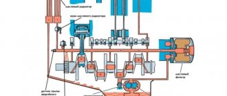
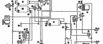
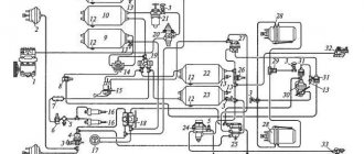
The GAZ-3307 vehicle is equipped with a brake drive with a fault signaling system, with separate braking of the axles ( see Fig. 3 ) and having a hydraulic vacuum booster and a vacuum cylinder with a shut-off valve in each circuit.
Fig.3. Diagram of the brake system Gas 3307.
I—vacuum; II—air; III—brake fluid; 1—intake manifold (spider) of the engine; 2—shut-off valve; 3—vacuum cylinder of the front circuit; 4—signalling devices; 5—hydraulic vacuum amplifier of the front circuit; 6—vacuum cylinder of the rear circuit; 7—rear wheel brake mechanism; 8—rear axle housing; 9—pressure regulator; 10—hydrovacuum amplifier of the rear kennel; 11—air filter; 12—sensor for emergency brake fluid level drop; 13—filling tank; 14—main cylinder; 15—front wheel brake mechanism.
Vacuum cylinders provide independent power to each circuit. The vacuum level is monitored by vacuum sensors with red indicators (on the instrument panel) for each circuit. The lighting of one of the indicator lamps indicates insufficient vacuum in the corresponding circuit.
A brake pressure regulator is installed in the hydraulic drive of the brake mechanisms of the rear wheels Gas 3307. Its functions in the event of failure of any of the two circuits are performed by the remaining serviceable circuit (front or rear axle).
At the same time, there is an increase in pedal travel by 90-115 mm. In this case, braking can occur with a gap between the pedal and the cabin floor of 15 mm.
Brake master cylinder (MBC).
Fig.4. Details of GTZ Gas 3307.
I—primary cavity; II—secondary cavity; 1—protective cap; 2—sensor for emergency brake fluid level drop; 3—additional tank; 4—connecting sleeve; 5—tube; 6—tank fitting; 7 and 20—hulls; 8—protective cap; 9—pusher; 10 and 18—pistons; 11—thrust bolt; 12—head sealing ring; 13—cuff; 14—piston head; 15—thrust rod; 16—return spring; 17—primary piston stop; 19—piston head spring; 21—secondary piston stop; 22—valve plate; 23—overpressure valve; 24—fitting.
Operating principle of GTZ Gas 3307.
The pistons of the main brake cylinder Gas 3307 are equipped with floating heads 14, which act as a bypass valve. In the initial (released) position, under the action of return springs 16, a gap is established between the head and the piston: the working cavities of the front and rear contours communicate with tank 3. ( see Fig. 4 ).
When you press the brake pedal, the pistons move, the heads 14, under the action of the springs 19, are pressed against the end of the pistons, separating the working cavities from the reservoir, and pressure is created in the drive. The seal is ensured by rubber rings 12 installed in the piston heads. Valves 23 maintain an excess brake fluid pressure of 40–80 kPa (0.4–0.8 kgf/cm2) in the system.
Failure of one of the circuits of the Gas 3307 brake system is accompanied by an increase in the brake pedal travel due to idle movement of the piston of the faulty circuit. A healthy circuit creates the brake fluid pressure necessary for braking.
Repair and maintenance of GTZ Gas 3307.
To replace worn parts, it is necessary to remove the unit from the car, disconnect housings 7 and 20, unscrew the thrust bolts 11 and remove the pistons. Before assembly, wash all parts with clean brake fluid. Do not allow foreign particles, dirt, or oil to enter the unit. Check for a gap of 0.4-1 mm between the end of the piston and the sealing ring 12 by pressing the head 14 with your hands until it stops. When assembling the unit, the thrust bolts 11 must fit into the grooves of the pistons.
Repair manual
Due to the fact that GAZ-3307 and GAZ-3309 trucks are domestic vehicles, their repair usually does not become an impossible task. Spare parts are available in any dismantling or automotive market.
Buying them is not a problem, and thanks to the availability of an accessible and understandable instruction manual, not only the service station technician, but also the owner of the car can replace relatively simple spare parts.
Getting a car owner's manual is not a problem. It can be downloaded from specialized websites on the Internet or bought a printed version in a store or market.
Name: GAZ-3307, 3309. Operation, maintenance and repair manual. Publisher: Third Rome Year: 2007 ISBN: 5-88924-367-3 Number of pages: 186 Format: PDF Size: 93.33 MB Language: Russian
Of course, if we talk about more serious breakdowns, then the owner will not be able to do the kind of diagnostics that can be carried out by technicians at a service station on his own. In addition, there are a sufficient number of users on the Internet who have been “communicating” with GAZ 3307 and GAZ 3309 for a long time, and will be able to share their experience. You can meet such people on forums dedicated to the repair and maintenance of this car.
Engine repair process
Brake system repair
Malfunctions of the brake system must be eliminated immediately or as soon as possible - brakes are directly related to traffic safety. Malfunctions include:
- Increased free play of the brake pedal, in some cases the brakes do not grab the first time, and the part requires two pedal strokes or more;
- Pedal hardness. The pedal becomes tight, and braking efficiency decreases;
- The brake fluid level light in the car lights up, indicating a lack of fluid in the brake system;
- The brake pedal grabs at the very beginning or there is no free play at all.
Diagram of the brake system of GAZ 3307
- The master brake cylinder has failed. As a rule, one of the two circuits stops working in it. A malfunction of the brake master cylinder (MBC) is accompanied by increased travel or failure of the brake pedal;
- The brake booster diaphragm is torn. With such a defect, the brake pedal becomes hard and difficult to press;
- Brake pads are incorrectly adjusted or worn. The malfunction is characterized by increased pedal travel. The eccentrics on which the pads are attached may also be worn out;
- Air getting into the brake system. In this case, the brakes become hard and braking efficiency is lost. If air gets in, it is necessary to bleed the brakes;
Not available:
| № | Part code | Name | Part Information |
| 52-3507006 | Parking brake spare parts kit (for spare parts) | Quantity for 3307 1 Model 52 Group Brakes Subgroup Parking brake Part number 006 | Not available |
| 52-3507010 | Parking brake assembly | Quantity for 3307 1 Model 52 Group Brakes Subgroup Parking brake Part number 010 | Not available |
| 52-3507065 | Central brake shield reflector | Quantity for 3307 1 Model 52 Group Brakes Subgroup Parking brake Part number 065 | Not available |
| 201496-P8 | Bolt M10-6gх22 | Quantity per 3307 4 Galvanized coating | Not available |
| 52-3507011 | Central brake shield assembly | Quantity per 3307 1 OKPO add. 52-3507010 Model 52 Group Brakes Subgroup Parking brake Part number 011 | Not available |
| 51-3507083 | Central brake pad support | Quantity per 3307 2 OKPO add. 52-3507010 Model 51 Group Brakes Subgroup Parking brake Part serial number 083 | Not available |
| 51-3507048-B | Central brake primary shoe tension spring | Quantity per 3307 2 OKPO add. 52-3507010 Model 51 Group Brakes Subgroup Parking brake Serial part number 048 Additionally Interchangeable with a part previously released under the same number | Not available |
| 51-3507080 | Central brake adjustment housing | Quantity per 3307 1 OKPO add. 52-3507010 Model 51 Group Brakes Subgroup Parking brake Part serial number 080 | Not available |
| 11-2108 | Adjusting screw assembly | Quantity per 3307 1 OKPO add. 52-3507010 | Not available |
| 51-3507049 | Secondary shoe coupling spring | Quantity per 3307 2 OKPO add. 52-3507010 Model 51 Group Brakes Subgroup Parking brake Part number 049 | Not available |
| 11-2041 | Central brake release pad | Quantity per 3307 1 OKPO add. 52-3507010 | Not available |
| 296980-P16 | Plug 31 | Quantity per 3307 1 Coating leaded | Not available |
| 51-3507014 | Parking brake shoe with friction pad assembly | Quantity per 3307 2 OKPO add. 52-3507010 Model 51 Group Brakes Subgroup Parking brake Part number 014 | Not available |
| 52-3507063 | Central brake oil deflector gasket | Quantity for 3307 1 Model 52 Group Brakes Subgroup Parking brake Part number 063 | Not available |
| 224682-P8 | Screw M8-6gx16 | Quantity per 3307 2 Galvanized coating | Not available |
| 51-3507052-G2 | Parking brake drum | Quantity per 3307 1 Model 51 Group Brakes Subgroup Parking brake Serial part number 052 Additionally Interchangeable with a part previously released under the same number | Not available |
| 52-3507062 | Central brake oil deflector | Quantity for 3307 1 Model 52 Group Brakes Subgroup Parking brake Part number 062 | Not available |
| 51-3507018-B2 | Parking brake shoe assembly | Quantity per 3307 1 OKPO add. 51-3507014 Model 51 Group Brakes Subgroup Parking brake Serial part number 018 Additionally Interchangeable with a part previously released under the same number | Not available |
| 51-3507020-B | Friction lining of the central brake | Quantity per 3307 1 OKPO add. 51-3507014 Model 51 Group Brakes Subgroup Parking brake Serial part number 020 Additionally Interchangeable with a part previously released under the same number | Not available |
| 293997-P | Rivet 4.75x11 | Quantity per 3307 16 Coating without coating | Not available |
| 296955-P16 | Plug 25 | Quantity per 3307 1 Coating leaded | Not available |
| 51-3507074 | Central brake release pusher | Quantity per 3307 2 OKPO add. 52-3507010 Model 51 Group Brakes Subgroup Parking brake Part serial number 074 | Not available |
| 51-3507070 | Release mechanism housing | Quantity per 3307 1 OKPO add. 52-3507010 Model 51 Group Brakes Subgroup Parking brake Part serial number 070 | Not available |
| B11-906-200 | Ball (353087-S) GOST3722-81 (purchased product) | Quantity per 3307 2 | Not available |
| 51-3507072 | Central brake release mechanism ball housing | Quantity per 3307 1 OKPO add. 52-3507010 Model 51 Group Brakes Subgroup Parking brake Part serial number 072 | Not available |
| 51-3507073 | Stroke limiter for the central brake release mechanism ball housing | Quantity per 3307 1 OKPO add. 52-3507010 Model 51 Group Brakes Subgroup Parking brake Part serial number 073 | Not available |
Clutch repair
3307 trucks often operate at maximum loads. A fully loaded car cannot drive in one gear when going uphill, and shifting gears in this mode forces the clutch to work quite hard. In addition, the 3307 gearbox is not synchronized and requires double squeezing when changing from one gear to another. Due to the heavy load on the clutch, it often fails and has to be repaired.
Signs of poor clutch are determined by pedal pressure:
- It fails, the gears cannot be engaged;
- Doesn’t squeeze out completely and sticks up;
- The pedal is too “soft”;
- Large free movement, squeezing occurs at the very end.
There are cases when the pedal pressure is normal, but when the gear is engaged, the car does not move.
Clutch diagram for GAZ 3307
The cause of the malfunction can be almost all clutch parts. Often fail:
- “Basket” and clutch disc;
- Release bearing;
- Master and slave cylinder;
- Clutch fork.
A little more detail about each detail:
- Driven clutch disc. The wear of the disc linings can be determined without removing it from the car. You need to remove the clutch housing tray - and then the disc linings can be seen. Linings that are too thin indicate the need to replace the part. Sometimes the disc hub breaks, and then the car does not move when the gear is engaged. Such a malfunction can also be determined on the spot. Two people need to do the check. One squeezes the clutch with the engine not running, the other moves the disc with a screwdriver. The break will be noticeable by the uneven movement of the disk.
- Clutch drive disc (“basket”). The “basket” of a gasoline engine is claw-type (three legs), the height of the legs is adjusted using nuts. Accuracy is very important here - incorrect adjustment affects the movement of the car: when starting off and when changing gears. The car can:
- twitch at the beginning of movement;
- gears on an unadjusted clutch engage with a crunch;
- the clutch can “drive”, but the car will not move.
- Release bearing with bore. The unit consists of two parts - the hub and the bearing itself. The hub has an oiler - the rubbing surface on which the hub moves is lubricated. The bearing itself must have a lithol type lubricant inside. A dry bearing can jam, and in this case the varnishes of the clutch “basket” will instantly wear out.
- Clutch master and slave cylinders. If the master cylinder fails, the pedal becomes soft (“wobbly”) and the clutch periodically disappears. A faulty slave cylinder usually leaks. You can try changing the cuffs inside the cylinders, but if the parts are old enough, it is better to replace them.
- Release bearing fork (clutch fork). The part is very simple, but its malfunction can most often be seen only when the fork is removed. Three characteristic defects of the part:
- the tips in connection with the release bearing hub are worn out;
- the fork bursts in the area of the swivel joint (“soldier”) or in the place where the rod is attached;
- the fork bends.
How to convert brakes to gas 3307
Hi all. I won’t talk about the lyrics, but straight to the point. The topic for today, as you already understood, is about brakes.
Earlier in the logbook, I think I already mentioned that in the summer I tinkered with the brakes. No? Damn, okay, I'll tell you.
In the summer, one day while working, the warning lights for both brake circuits came on. I understood the matter immediately, it was time to look for and change the hoses on the VU or receivers. Well, I found a hose in my father’s garage, quite thick, the main thing is that the internal diameter is just what I need. But a fat person will live longer. Well, without thinking or wondering, I replaced all the hoses. I don’t remember how old they are. And almost all of them burst. I replaced it, but somehow didn’t think to bleed the brakes right away. Started it up, honked the horn, drove it - everything was OK. Well, the job is done, I thought, and in the morning we successfully ran to work.
On the way, I began to notice that the brake circuit warning lights were lighting up at high speeds. At idle it seems fine. At the first successful opportunity, I opened the book to look through what else could be there, maybe I missed something? And it's true. After eliminating the malfunction, and in my case replacing the burst hoses, it is necessary to bleed the brakes and return the pistons of the warning device to their original position. Oh yes, it was mid-July.
I left for the working day with tears in my eyes, well at least not until the evening, but until 16 o’clock and then went straight home. At home my brother and I started pumping the brakes. To be honest, I have never pumped them for so long before. I used up the liter of brake fluid I bought, but the air keeps coming and going. It got dark. We left the whole thing until the morning.
In the morning, we got up early and went to continue pumping. I pumped these brakes, most likely with a hack. The air was still flowing, but it seemed to take the first time to press. Well, okay, off to work. The car runs smoothly, the brakes are not bad, and the warning lights do not come on. I'm happy, but for some reason cats scratch in my soul. And onto the scrapers. After a few days, 5-6 days it seems I waited. My fear, or my doubt, resulted in the fact that the braking efficiency has dropped and when you walk on the brakes for a long time, the pedal sinks. The warning lights started to light up. At first it blinked and then the malfunction indicator in the front circuit came on. After the indicator has been on for a long time, the rear circuit also lights up. Damn, they've arrived. “The problem is in the GTZ, it doesn’t hold the pressure,” I thought.
Well, I went to the store, bought a repair kit for the GTZ, brake fluid and went home. I don’t know, RosDOT (or as they call it “Turtle”), isn’t it good? The seller recommended it to me well.
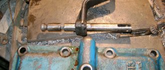
I came home, had a snack and went to remove the GTZ. The nuts and the fitting got on my nerves, especially the fitting, until I gave it a good whack with a hammer. I took it apart, and the cuffs were not in bad condition, only there was some dirt, “Mother, don’t worry.” Well, again, they were in good condition, they were soft, unlike the new ones. I washed everything, wiped it, lubricated it and assembled it. I didn’t notice much change, I just started biting the piston in the GTZ and it came back very slowly.
I had to disassemble it again and a couple of cuffs that were getting snagged had to be replaced with old ones. I assembled it and hurray, the brakes are back. I spread the pads a little, bled the brakes and hallelujah. I even miss those brakes. The brakes are just a bomb.
But after 2 weeks of work, something hisses somewhere again. I heard this when I arrived home after work, turned off the engine and heard a hissing sound. I ran through the hoses and there was nothing suspicious. I lifted the body and didn’t even need to look closely. There is a hole in the VU master cylinder cover. That's where the air comes from. It's on the front edge.
I couldn’t find the donor, so I covered it up with cold welding. I removed all the debris from it and checked it. It's not clear somehow. Bleeded the brakes. The rear holds up and brakes well, but the front doesn’t, it barely grips. And the VU seems to have stopped working or something, I couldn’t figure it out. I bought a repair kit at VU, I will continue to do so. My father also found it in the village and removed the complete VU from an old car. He tells me to put it on.
And like this all summer, it would seem that everything goes by in days, but I was busy with them from mid-July until now. I will continue working on Friday and add to the bortovik.
Friday.
Well, Friday has come. I'm trying to solve the problem with the brakes again. The VU was removed, the cuffs on it were replaced and installed in place. Then I pumped the front circuit again. Let me remind you that the back grips, but the front grips poorly, barely.