Modifications
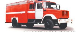
Based on the basic all-terrain vehicles, the Ural Automobile Plant produced a number of modifications intended for military or civilian use. Some versions are manufactured by third parties that receive the chassis from the chassis manufacturer. Vehicles are shipped equipped with both standard suspension and reinforced front axle springs. Such cars are designated as Ural-43203.
Onboard
The flatbed version is the most common. There are trucks that differ in platform size and side height. There is a car model built on the long wheelbase chassis 4320-19. Lengthening the platform made it possible to place cargo weighing up to 12 tons.
Device
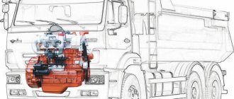
Ural vehicles use an all-metal cabin designed for 3 people. The power unit, closed by the hood, is located in front of the driver. This arrangement provides good protection for the vehicle’s crew in the event of a mine explosion, but impairs visibility for the driver. The Ural clutch device includes a pneumohydraulic booster, which reduces the level of physical activity. Behind the cabin there is a platform or other equipment.
Electrical equipment
The electrical circuit of the Ural-4320 is single-wire, with an operating voltage of 24V. The negative terminal of the battery is connected to the body and body parts. Wiring harnesses are routed in the truck cab and under the bed.
The electrical circuit of cars is protected by cylindrical fuses designed for a current of 8-16A. To protect against short circuits, a bimetallic insert is installed, triggered at a current of 30A. The node is reusable. The electrical wiring is colored insulated, which simplifies repair and maintenance.
Brake system
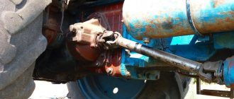
The Ural brake system has a mixed drive. When you press the brake pedal, the pneumatic booster is activated, which transmits pressure to the hydraulic lines. The working fluid enters the actuator cylinders and presses the pads to the surface of the brake drums. The hydraulic drive is divided into 2 circuits: the first serves the front and middle axles, and the second serves only the rear axle. If any circuit breaks down, the remaining one provides full braking of the car.
At the output of the transfer gear shaft of the all-terrain vehicle there is a separate drum mechanism, which is a parking brake. Switching on is carried out using a lever located in the driver's cabin. A pneumatically controlled auxiliary brake, called a mountain brake, is installed in the engine exhaust pipe. When a control signal is applied, the gas exhaust channel is blocked and the fuel supply is simultaneously turned off.
Cooling system
The engines of the all-terrain vehicle have a closed forced-type cooling system; the coolant is a special liquid Tosol-A. Short-term filling of lines with distilled water is allowed. In winter, the water must be drained while it is parked, since when it freezes there is a risk of the jacket rupturing.
The heat exchanger is a tubular-plate radiator; the air flow through the honeycomb is created using a fan. There are 2 thermostats in the system lines that maintain the engine temperature within the required limits. Fluid circulation is carried out by a mechanical pump driven by a belt from the crankshaft.
To make it easier to start the engine in winter, a pre-heater PZD 30 is used, running on diesel fuel. The design of the device has an electric pump that ensures fluid circulation and uniform heating.
Air system
The power unit contains a two-cylinder compressor, which is a source of compressed air. The all-terrain vehicle is equipped with several receivers for storing a supply of compressed gas. The cabin has a dial pressure gauge for the pneumatic system. The trucks are equipped with a centralized tire inflation system, which improves the off-road parameters of the Ural vehicle. Windshield wipers and a PSU installed in the clutch drive are connected to the pneumatic lines.
Transmission
Transmission models for the Urals depend on the version of the installed engine. Early cars used a KamAZ 141 five-speed manual transmission. The clutch was a dry type, equipped with 2 working discs. When using engines from the Yaroslavl plant, a five-speed YaMZ 236 gearbox and a single-plate clutch are installed. The control drive uses a hydraulic drive and a pneumatic amplifier. In the cabin there is an information plate with a Ural gear shift diagram.
On the gearbox housing there is a standard place for installing a power take-off gearbox. There are several models that allow operation only when parked or while the all-terrain vehicle is moving.
The transmission has a two-speed transfer gearbox that proportionally distributes power flows between the front axle and the rear bogie. The transfer case includes a center differential equipped with a pneumatically driven lock. Both gears of the Ural transfer case are low, the gear ratios depend on the model of the power unit. A description of the gearbox control circuit is available on a plate attached to the instrument panel.
History of the development of the model design
The Ural M 62 motorcycle, 650 cm cubed, was created in 1961 by the Irbit Motorcycle Plant on the basis of the M 72M motorcycle.
After the Irbit plant created a new forced overhead valve engine and began installing it on the M 72 motorcycle, a transitional model appeared - the M 61.
The M62 motorcycle is a modernized model of the M 61 and differs from it in the design of the power transmission, chassis and ignition system devices. The main technical parameters of the engine remained unchanged.
The engines are overhead valve and were manufactured on the basis of the M 72M engine, therefore only their distinctive features are described in comparison with the design of the M 72M engine.
The crank with connecting rods is an integral unit, which differs from the corresponding unit of the M 72M engine in the length of the connecting rod and the distance from the axis of the axle to the axis of the crank pin.
A second oil scraper ring is installed on the lower part of the piston skirt.
The cylinders are interchangeable and in the upper part have four holes for the head mounting studs and two holes into which the pusher rod tubes are pressed.
To drain oil from the valve box into the crankcase, there is a tube passing through the cylinder ribs.
Diagram of the gas distribution mechanism of the M 62 engine.
The gas distribution mechanism of the described engine is an overhead valve mechanism, which is its fundamental difference from the M 72M engine.
The valve disc diameter is 35mm, the stem diameter is 7.5mm and the overall valve length is 91mm. The valves move in guides pressed into the body of the cylinder head. The gap between the bushing and the valve stem is 0.05-0.1 mm.
The camshaft has four camshafts, which differ from the cams of the M72M engine shaft in their shape and location, which makes the camshafts not interchangeable.
Tips with a hemispherical recess are pressed into the body of the pushers.
The thermal gap (0.1 mm) between the valve stem and the rocker arm is adjusted with the valve box cover removed.
Lubrication system
Valves and rocker arms are splash lubricated. Through holes located at the end of the pushrod guide bushings and the rod casing, oil enters the cylinder heads and is sprayed there by the valve springs.
Supply system
The M 61 engine has two K-52 carburetors, and the M 62 engine has two K-38 carburetors. Two K-37 carburetors can be installed on the M61 motorcycle engine.
Return to contents — ↑
Operation and repair manual
Each vehicle comes with an instruction manual. Before starting operation, you must familiarize yourself with the manufacturer’s recommendations, which will allow you to avoid breakdowns and costly repairs.
- After starting a cold power unit, do not allow operation at high speeds. Movement is allowed to begin only after warming up to +40°C.
- If the engine was running at high speeds under load, then it should idle for 2-3 minutes before stopping. Such manipulation is necessary for uniform cooling of structural elements.
- It is forbidden to completely drain the fuel from the tanks, as this leads to air entering the fuel supply system.
- When driving on hard ground, it is not recommended to engage the center differential. When blocked, accelerated wear of transmission elements and tires begins.
- It is prohibited to drive on a rut with the steering wheel turned all the way.
- Movement should begin only after reaching a pressure of 4 kgf/cm² in the pneumatic system. At a reduced value, the vehicle's braking system does not provide effective deceleration.
When operating equipment, there are several types of maintenance:
- Daily, which is carried out when the car leaves the route and immediately after returning.
- Seasonal, produced in spring and autumn.
- The next one, which comes in categories TO-1 or TO-2 (after 4000 and 16000 km, respectively). It is also possible to carry out work according to the engine hour meters - after 125 or 500 hours of engine operation.
The required list of actions is given in the service instructions. The manufacturers and types of technical fluids that must be used when replacing are also indicated there. It is not recommended to use materials that differ in characteristics from the manufacturer's recommendations.
Technical characteristics of the motorcycle Ural M 62
Total information
Motorcycle type - With sidecar Base, mm - 1435 Ground clearance, mm - 125 Track, mm - 1100 Dimensions, mm: Length - 2420 Width - 1650 Height (by ignition key) - 1000 Motorcycle weight, kg: dry - 340 working - 366 Fuel consumption on the highway, l/100 km -6.0 Fuel reserve on the highway, km - 300 Highest speed, km/h - 100 Capacity (oil), l: engine crankcase - 2.0 Gearbox crankcase - 0.8 reverse gear housing - 0.150 air cleaner - 0.2 Fuel tank capacity, l - 22
Engine
Engine type - Four-stroke two-cylinder Brand - M - 62 Cylinder diameter, mm - 78 Piston stroke, mm -68 Displacement, cm cubed - 649 Compression ratio - 6.2 ± 0.2 Maximum power, l. With. — 28 Maximum torque, kg m — 4.5 Block head material — aluminum alloy Head gasket — Asbestos metal 0.6 mm Piston material — aluminum alloy Valve distribution phases (by crank angle), deg.: beginning of intake to c. m.t. - 57 end of intake after n. m.t. -77 beginning of production BC m. t. - 97 end of release after century. m.t. - 37 Carburetor - Two K - 38
Power train or transmission
Main gear ratio - 4.62 Clutch - Dry double-disc in the engine flywheel Number of disks: driving - 3 driven - 2 Number of springs - 6
Transmission
Type - Four-speed two-way Gear ratios: in first gear - 3.6 in second gear - 2.286 in third gear - 1.7 in fourth gear - 1.3 Total gear ratio: in first gear - 16.65 in second gear - 10, 56 in third gear - 7.85 in fourth gear - 6.01
Tires
Size, in inches - 3.75-19 Pressure, kg/cm squared: front wheel - 1.8 rear wheel - 2.2 stroller wheels - 2.0 spare wheel - 2.2
Ignition Electrical equipment
Type - battery magneto Ignition coil brand - B - 201 Battery - 3 M T - 14 Generator - G - 402 Regulator relay - R R - 302 Signal - S - 23 Headlight - F G - 116
Return to contents — ↑