Kamaz rear suspension
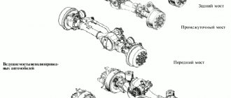
The rear suspension of three-axle cars is balanced on two springs.
With this suspension, the intermediate and rear axles swing relative to the balancer axis
In this case, the springs perceive only the force of gravity of the car; other forces and moments are transmitted by pushers and reaction rods.
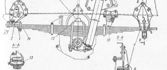
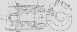
The balance suspension of the intermediate and rear axles of the KamAZ-5320 vehicle is shown in Fig. 1
The rods pivotally connecting the axles to the frame form a lever suspension in the form of a parallelogram
On the brackets attached to the frame side members, the balancing device brackets into which the axle is pressed are secured with studs and nuts.
The shoe can be rotated on an axis in two bronze bushings, held from axial displacement by a split nut tightened with a bolt.
The middle of an inverted semi-elliptical spring is attached to the shoe with stepladders and a pad.
The ends of the springs are installed on supports.
When the springs bend, their ends slide in the supports.
When the axles move downwards, the springs are held in the supports by fingers.
Pushing forces and reaction moments are transmitted to the frame by six reaction rods. The reaction rod hinges are self-clamping.
The ball pins of the hinges are located between the spherical liners 5 and 7. To seal the hinge from leakage of lubricant and dirt, an end seal 8 is installed
Based on the distance between the centers of the tip holes, reaction rods are divided into four selective groups. The rods of adjacent groups may differ in length by 0.6...1.2 mm.
The lower suspension rods have one group, since with an unfavorable combination of sizes, it is possible to install the intermediate and rear axles at an angle to each other, which increases fuel consumption and causes increased tire wear.
The installation of upper suspension rods by group is not regulated. The group marking is marked on the head of the rod end and is covered by the hinge seal.
The suspension distributes loads evenly between the intermediate and rear axles, and they can move up and down independently of each other as a result of the rotation of the shoe.
The possibility of relative angular transverse misalignment of bridges when a vehicle moves on an uneven road is due to the sliding of the ends of the springs in the supports.
The rear suspension of KamAZ-53212, -54112, -5511 vehicles, unlike other vehicles, has a balancing device with one axis (Fig. 4), which also serves as a balancer tie.
The springs of this suspension are reinforced and consist of 14 leaves instead of 9.
The first, second, third and last sheets of this spring are rectangular in section, the remaining sheets are T-shaped.
To fasten the spring to the shoe, reinforced stepladders 2 are used.
On KamAZ-4310 vehicles, the rear spring step nuts are secured against self-loosening with locknuts.
_______________________________________________________________________________
Front and rear suspension of Kamaz trucks
The suspension of a Kamaz vehicle absorbs the main dynamic loads from the impact of road irregularities. To ensure a smoother ride and dampen vibrations, double-acting hydraulic shock absorbers are installed in the front suspension of the Kamaz. Kamaz front suspension For different models and configurations, Kamaz front and rear suspensions are installed that differ in: the springs used, depending on the load; for front suspensions - with a stabilizer bar; shock absorbers and shock absorber mounting brackets; additional buffers and their design; stepladders and fastening elements.
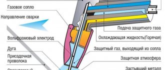
Fig.1. Front suspension KamAZ-5320, 5410, 55111 1 — eye fastening bolt; 2, 17 — coupling bolts; 3 — ear pad; 4 — car frame; 5, 10 — upper and lower shock absorber brackets; 6 — spring buffer; 7 — spring stepladder; 8 — overlay; 9 – pin; 11 — shock absorber; 12 - clamp; 13 — rear spring bracket; 14 — cracker finger; 15 - cracker; 16 - overlay of the root sheet; 18 — bushing; 19 — liner; 20 — front spring bracket; 21 - ear finger; 22 - ear bushing; 23 — spring eye; 24 – oiler Kamaz-5320, 55111 front suspension (Fig. 1) consists of two longitudinal semi-elliptical springs, working together with two telescopic shock absorbers and two hollow rubber compression buffers. In the middle part of the springs are attached by two stepladders 7 to the front axle beam area. Between the springs and the Kamaz beam, brackets 10 of shock absorbers 11 are installed. The front ends of the springs are attached to the brackets 20 using detachable lugs 23 and pins 21. The bushings 22 of the detachable lugs are made of anti-friction malleable cast iron, which increases the wear resistance of connections with the pins of the springs. The rear ends of the front springs of the Kamaz-5320, 55111 suspension are sliding and rest on replaceable protective crackers 15 and side liners 19. The main leaf of the spring is of rectangular section, and the remaining leaves are of T-shaped section. Total 15 sheets. An overlay 16 is secured to the sliding end of the main sheet with rivets, protecting it from wear. The spring pins are lubricated through an oiler. Kamaz shock absorbers Front suspension shock absorbers KamAZ-5320, 55111 are connected to the vehicle frame and front axle using pins and rubber bushings. The bushings compensate for distortions and soften shock loads transmitted from the vehicle axle to the frame. Washers are installed at both ends of the rubber bushings. When a Kamaz vehicle moves along a road with small obstacles, the amplitude of suspension vibrations is insignificant and the resistance created by the shock absorbers is small. On an uneven road, the vibration amplitude of the Kamaz suspension increases, while the shock absorber provides great resistance, preventing the vehicle from swaying and absorbing energy both during smooth and sharp compression and recoil of the springs. To limit the travel of the Kamaz front suspension, rubber hollow buffers 6 are used, mounted on the frame side members. Fig.2. Front suspension stabilizer Kamaz-53212, 65115 The front suspension of Kamaz-53212, Kamaz-65115, Kamaz-53228, 53229 and 54112 vehicles has a stabilizer bar, which increases the angular stiffness of the suspension, reducing the roll angle of the sprung part of the vehicle when the vehicle is subjected to transverse (lateral) ) force, increases vehicle stability. The stabilizer bar in the middle part is fixed to the front axle beam in rubber cushions using clips, pads and stepladders. The Kamaz suspension stabilizer bar is pivotally connected by struts to brackets installed on the left and right side members of the frame. Connecting the struts to the frame brackets is similar to attaching a shock absorber. Fig.3. Shock absorber for Kamaz-5320, 55111 1 - eye; 2 — tank nut; 3 — rod seal; 4-tank nut seal; 5 - bypass valve; 6 — hole in the outer row; 7 — recoil valve; 8, 11, 22 — springs; 9 — compression bypass valve; 10 - compression valve; 12 - nut; 13 — bypass valve holes; 14 - piston; 15 - hole in the inner row; 16 — piston ring; 17- tank body; 18 — working cylinder; 19 — piston rod; 20 — rod guide; 21 — guide oil seal; 23 — seal ring; 24 — rod seals; A - hole for draining liquid into the tank; B - reservoir cavity The Kamaz shock absorber (Fig. 3) is attached with the upper eye to the bracket on the frame, and the lower eye is attached to the lower shock absorber bracket. The operating principle of Kamaz hydraulic shock absorbers is as follows. With relative movements of the sprung and unsprung parts of the car, the liquid in the shock absorber, flowing from one cavity to another through small holes, resists the vertical movement of the rod and dampens the vibrations of the springs. Kamaz rear suspension The Kamaz rear suspension is a balancer, on two semi-elliptical springs, with reaction bars with rubber-metal hinges (see Fig. 4). The ends of the springs slide on supports welded to the bridge beams.
Fig.4. Rear suspension KamAZ-5320, 53212 1 - rear spring buffer; 2 — reaction lever; 3 – spring; 4 — reaction rod; 5 – nut; 6 — spring pad; 7 – spring stepladder; 8 — spring support pin; 9, 16 — studs; 10 — expansion sleeve; 11 — spring support; 12 — rear axle; 13 — bracket for the lower reaction rod; 14 — intermediate bridge; 15 - bracket for the upper reaction rod; 17 — spar; 18 — rear suspension bracket gasket; 19 — spring shoe; 20 — shoe cover gasket; 21 — shoe fastening nut; 22 — filler plug; 23 – shoe cover; 24 — bolt of the coupling nut for securing the shoe; 25 – shoe bushing; 26 — sealing ring; 27 - thrust ring; 28 — cuff; 29 — nut for fastening the bracket tie; 30 — cuff clip; 31 — shoe axis; 32 - ball pin fastening nut; 33 - balancer bracket; 34-brace of balancer brackets
The Kamaz balancer axis is made of one piece, without a coupler. The reaction rod pins are nitrided and the spring supports are reinforced. The springs in the middle part are attached by stepladders 7 to the spring shoe 19. The ends of the springs are installed in supports 11 (Fig. 5). When the springs bend, their ends slide in the supports. When Kamaz axles move downwards, the springs are held in the supports by fingers 8, secured from axial movements by cotter pins and washers. To limit the upward stroke of KamAZ axles and soften their impacts on the frame, buffers 1 are installed on the side members. Pushing forces and reaction moments are transmitted to the frame by six reaction rods 4. The reaction rod hinges are self-moving.
Fig.5. Installation of rear suspension KamAZ 43101, 43114, 43118 1 - intermediate axle; 2 - frame; 3 — upper reaction lever; 4 — studs; 5 - jet rods; 6, 10, 13 — bolts; 7 — spring stepladder; 8 — spring pad; 9 — stepladder nut; 11 — support finger; 12 — buffer lining; 14 — buffer; 15 — ball pin cover; 16 — support; 17 — rear axle; 18, 22 — lower reaction arms; 19 - balancer axis bracket; 20 — filler plug; 21 - spring The balancing device of Kamaz-5320, 55102 and 5410 vehicles consists of two axles 31 pressed into brackets 33, and shoes 19 with bushings 25 pressed into them made of antifriction material. The Kamaz balancing device brackets are connected by tie rod 34 and secured with studs to the rear suspension brackets, which in turn are bolted to the frame side members. Cover 23 has a hole with a plug for filling oil. To prevent lubricant leakage, reinforced rubber cuffs are installed in the shoes, and O-rings are installed to protect the seals from dirt. Shoes 19 are secured to the axles with split nuts, tightened with bolts 24.
Fig.6. Rear suspension KamAZ-55111, 53112 Rear suspension KamAZ-53212, 55111 and 54112 (Fig. 6), in contrast to the rear suspension shown in Fig. 67, has a balancing device with one axis pressed into the balancer axis bracket and acting as a coupler. To improve repairability, the spring supports and lower reaction arms of Kamaz are made removable. The supports are secured against movement by mounting plates. To limit the downward travel of the axles, axle swing limiters are installed on the spring supports. Kamaz jet rods Kamaz jet rods (Fig. 7) are identical in design. In each tip of the reaction rod there is a hole bored into which an internal liner 7 is installed, which is fixed in the tip with a rivet 6, a ball pin 8 and an outer liner 9 to prevent it from turning.
Fig.7. Kamaz 1 reaction rod - oiler; 2 - nut; 3 - spring washer; 4 - oil seal; 5 — rod; 6 - rivet; 7 — inner liner; 8 - finger; 9 — outer liner; 10 - spring; 11 - gasket; 12 - cover The outer liner is pressed by a spring and closed with a cover with a sealing gasket 11. To lubricate the liners, an oiler 1 is installed in each cover. To seal the hinge of the Kamaz reaction rod from leakage of lubricant and dirt, an end seal 4 is installed with an interference fit on the conical surface of the pin: it is one the side rests against the end of the lever bracket, the other, working, is pressed against the end of the tip of the rod.
_______________________________________________________________________________
_______________________________________________________________________________
_______________________________________________________________________________
- Clutch KamAZ-5320 and its components
- Repair of PGU and Kamaz clutch master cylinder
- Gearbox gearbox KamAZ 141
- Gearbox gearbox KamAZ ZF 16
- Gearbox 152 Kamaz with divider
- Gearbox gearbox 154 Kamaz
- Gearbox Kamaz-4308
- Clutch of a Kamaz-4308 car
- Clutch and gearbox KamAZ-65115
- Disassembly and assembly of Kamaz-4310, 55111, 43118 gearboxes
_______________________________________________________________________________
- Cylinder block, head and valves Kamaz-740
- Fuel system of Kamaz-740 diesel engine
- Adjustments and repairs of fuel injection pump Kamaz-740
- Drive axles of the Kamaz-4310 vehicle
- Repair of Kamaz drive axle gearbox
- Rear axle KamAZ-4308
- Axles and suspensions of Kamaz-65115 dump trucks
- Installation of Kamaz cardan shafts and axles
- Repair of Kamaz vehicle transfer case
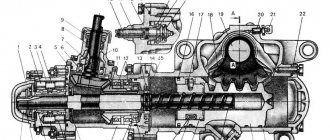
- Kamaz power steering - adjustments and repairs
- Repair of Kamaz steering gear parts
- Steering parts Kamaz-4308
- Parts of the brake system Kamaz-4308
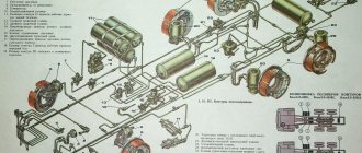
- Brake system and brake drive Kamaz
- Repair of brake valves and Kamaz compressor
- Suspension Kamaz-4310, 55111, 43118 and their parts
- Frame and suspension of the Kamaz-4308 car
- Cabin details and platform KamAZ-65115
- Cabin components Kamaz-4308
- Platform mechanism of Kamaz vehicles
- Klintsy KS 65719-5K truck crane based on KamAZ-6522 chassis
- Truck crane KC-35719-7-02 based on Kamaz-43118 chassis
- Truck crane Galichanin KC-55713-1K based on KamAZ-65115 6x4
- Ivanovets KS-45717K-1/1R truck crane based on KamAZ-65115 chassis
- Ivanovets KS-3577-3/4 truck crane on KamAZ-43253 4x2 chassis