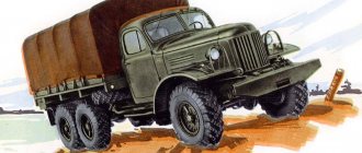
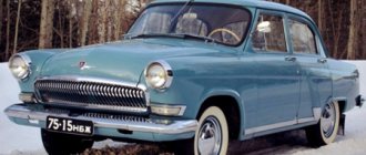
At the end of the 1950s, the era of large-scale construction of inexpensive housing, which was called “Khrushchev”, began in the Soviet Union. At the same time, new ZIL-164 vehicles began to appear on construction sites. It is with these trucks that the older generation associates warm memories of their Komsomol youth and the joy of getting new apartments.
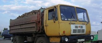
In the first half of the 60s, ZIL-164 dump trucks appeared in huge numbers. They carried concrete and other materials for construction. Onboard models were also used to transport workers.
Differences between ZIL-164 and ZIS-150
The new truck was created at the Likhachev plant as a successor to the ZIS-150, which at that time was considered quite outdated. Although the latest modifications of the ZIS-150 were practically no different from the first ZIL-164, the batch did not require another modernization, but the creation of a completely new model, so in 1957, designers created a new car based on the ZIS.
Its appearance immediately suggested that it was a modernized ZIS, but there were still some differences in the design of the models:
- The car frame has become more powerful;
- The engine was also more powerful;
- A new model carburetor was installed;
- Telescopic shock absorbers appeared;
- A windshield blowing system has appeared;
- New design heater.
In addition, many other small changes were made to the design of the car, which are invisible at first glance. For example, a new radiator, higher fenders, etc.
The new ZIL can be considered a successor not only to the ZIS-150, but even to the legendary three-ton ZIS-5. Despite all the improvements and modernizations, the new ZIL had much in common with its ancestor that went through the Great Patriotic War. The war crossed out many plans of the factory workers, so the ZIS-150 appeared only after the Great Victory.
The car began to be mass-produced in 1957, and was produced until 1964. In 1961, a major modernization of the car took place, as the plant was preparing to produce a completely new ZIL-130 truck. Since 1961, the plant has produced the ZIL-164A model, which received some of the components from the new, more advanced model. The latest modification received a new single-disc clutch, cardans, and brake valve. In addition, the ZIL-164A gearbox was also taken from the model with index 130.
Some sources indicate that the first modifications of the ZIL-164 were called ZIS, but this is not true. The plant was renamed in 1956, the first cars rolled off the assembly line only a year after that, but the ZIS-150 was really called ZIL. The latest models, which were produced in 1956, had the inscription “ZIL”.
Variety of the ZIL-164 model range
Over the years of production of the ZIL-164, many modifications of this truck have been created. Most of them were used on construction sites and in agriculture. Here are the main models of this car, popular in the 1960s:
- The basic ZIL-164 models are a flatbed truck. They have a wooden body with three folding sides;
- ZIL-164R is an improved model that has a more powerful engine developing up to 109 hp. In addition to engines, they were distinguished by carburetors of the MKZ-K-84 model. These modifications were specifically designed to work as tractors that could tow trailers weighing up to 4.5 tons. If a basic modification of a truck was not recommended to be constantly operated with a trailer, then this model was intended for just that;
- ZIL-164D – special modifications of onboard vehicles equipped with shielded electrical equipment;
- ZIL-164G - a chassis on which special equipment and cargo platforms of various types, intended for specific needs, were installed;
- ZIL-MMZ-164N is a real truck tractor. Also equipped with a new carburetor and a forced engine;
- ZIL-MMZ-585I – construction dump truck;
- ZIL-MMZ-5875K – agricultural dump truck.
Since 1961, all these modifications received the letter “A” after the model number, for example, ZIL-164AR. Dump trucks, which were produced since 1961, were designated by the indices 585L and 585M.
In addition, the Likhachev plant embarked on an interesting experiment and began producing trucks designed to operate on liquefied gas. These were modifications ZIL-156A, ZIL-166 and ZIL-166A. The technical characteristics of this car made it possible to operate it not only on gas, but also on gasoline. Since the production of gasoline in the 60s was excessive, and it itself cost a penny, gas modifications were extremely rare.
In the last years of production, the design of the ZIL-150 car underwent significant changes, which, together with changes in the appearance of the car, ultimately led to a change in the index - in October 1957, the modernized model received the name ZIL-164. In fact, most of the design innovations usually attributed to the ZIL-164 truck, namely: an aluminum cylinder head, a new engine oil sump, a gas pipeline with a central gas outlet, a sealed fuel pump, a high-flow oil pump, as well as a front suspension with shock absorbers and sealing The ends of the springs in rubber cushions were introduced on its predecessor in 1956-1957. In fact, the updated car had the following differences: – new radiator trim; – tail with modified hood sides and wings raised by 20 mm; – front wing brackets with changed overall dimensions and rear wing brackets with changed configuration and overall dimensions (due to wing lift); – reinforced engine mudguards 1 mm thick instead of 0.8 mm; – a radiator with an increased cooling surface with 190 cooling plates (versus 125 on the ZIL-150) with a reduced pitch between them (3 mm instead of 4.5 mm), elongated tubes (by reducing the height of the lower tank by 29 mm) and new larger louvers height (595 mm versus 566 mm) with nine plates (instead of seven on the ZIL-150); – fan casing (diffuser) in the engine cooling system; – a muffler with a modified configuration of the exhaust pipe, curved and elongated in order to prevent heating of the brake chambers by exhaust gases; – a fuel tank without a central stiffener in the bottom, with partitions only on the side surfaces; – rear cabin suspension, unified with the ZIL-157 suspension; – the KP5-E instrument panel, which differed from the KP5-Zh instrument panel installed on the ZIL-150, in the location and design of the instruments (the fuel level indicator, water temperature indicator and lubrication system pressure gauge changed their location; the arrow axes of the ammeter and water thermometer were located in the upper part dials), as well as the presence of one turn signal indicator lamp; – a flexible speedometer shaft of type GV17-V with outer squares (ends of a square-section cable protruding from the ends of the shaft) on both sides? introduced to replace the flexible shaft of the GV17-B speedometer, in which the cable on the drive side was equipped with a tip with an internal square; – an improved gearbox with the following innovations: 1) to eliminate oil leaks, a rubber oil seal was introduced at the output end of the secondary shaft, protected from dirt and mechanical damage by a reflector (two mud rings connected by spot welding) installed in the recesses of the shaft flange; 2) a sealing gasket with a closed contour of holes for bolts under the rear bearing cover of the secondary shaft was introduced, as a result of which the width of the bearing retaining ring was reduced from 7 mm to 5 mm; 3) to reduce the ingress of oil into the cavity of the bearing cover and metal dust into the bearing, instead of the rear bearing of the input shaft, GPZ No. 50213 began to be installed with GPZ No. 150213 with a protective washer; 4) in order to eliminate cases of rupture of the puller bolt when dismantling the axle of the reverse gear block, the diameter of the threaded hole for the bolt in the axle was increased from 12 mm to 14 mm, and the groove for the stopper was replaced with an annular groove; 5) to prevent an increase in pressure in the crankcase and reduce oil leakage, a breather is installed in the box cover; 6) in connection with the installation of a new flexible shaft, the drive worm and the driven gear of the speedometer drive (except for the ZIL-164N chassis) changed, as well as the direction of output of the driven gear of the drive; 7) due to the introduction of a rubber oil seal for the secondary shaft and a new drive mechanism for the flexible speedometer shaft, the design of the secondary shaft rear bearing cover has changed. As a result of the introduction of a new flexible speedometer shaft, the route of the shaft from the gearbox to the instrument panel was changed. Instead of radiator cladding with horizontal slots, blinds began to be installed with cladding with vertical slots. The wings of the ZIL-164 were raised by 20 mm compared to the ZIL-150, and therefore the height of the hood sides was correspondingly reduced, the design of its fasteners and their fastening were changed, and the wing brackets and their installation locations on the wings and frame side members were changed. It should be noted that despite the significant improvement in the design of the truck, its load capacity and basic technical characteristics remained the same. Since October 1961, the plant switched to producing the modernized ZIL-164A truck.BRIEF TECHNICAL DESCRIPTION:
A 4x2 truck with a carrying capacity of 4000 kg on paved roads. The car was equipped with a 6-cylinder carburetor four-stroke in-line lower-valve engine, which, after several previous upgrades, finally received a new name on October 1, 1957 - ZIL-164. Engine power was 97 hp. at 2600 rpm (with limiter), maximum torque - 33 kgm at 1100-1400 rpm, compression ratio 6.2, displacement 5555 cc. The power supply system is forced, with gasoline supplied by a sealed B-6 diaphragm-type fuel pump. The main filter-settler is a mesh type, with a filter element made of galvanized steel mesh. A gas tank with a capacity of 150 liters with a mesh filter in the filler neck was located on the left side member of the frame. Fuel - A-66 gasoline. Carburetor - MKZ-K-82, with a falling flow, with a balanced float chamber, an economizer and an accelerator pump, equipped with a separate pneumatic limiter for the maximum number of crankshaft revolutions, which limited the maximum speed of the car to 75 km/h. The accelerator pump drive is mechanical. Two economizer valves were installed on the carburetor - with mechanical and pneumatic drives. Air filter – VM-12, mesh, inertial oil, with two-stage air purification and a filter element made of steel mesh. The lubrication system is combined: under pressure and splashing, with coarse and fine oil filters located in one housing. Coarse filter - slot type, with a filter element made of a set of thin steel plates; fine filter - plate, with a cardboard filter element ASFO-1 (automotive superfilter-settler No. 1) or DASFO-EFA-1 (two-way automobile superfilter-settler, vigorously filtering cars). The oil pump is single-section, with a floating oil receiver. The crankcase ventilation system is forced (closed type), valveless, with gas suction into the intake gas pipeline. The cooling system is liquid, closed, with forced circulation of coolant, carried out using a centrifugal water pump. Radiator – tubular-plate, four-row. The system also included a six-blade fan and a liquid-type thermostat. Clutch – double-disc, dry, with mechanical drive. The gearbox is a three-way, five-speed (five forward gears, one reverse, the fourth gear is direct, the fifth is overdrive). The cardan transmission is an open type with two cardan shafts (intermediate and main), a support on the intermediate shaft and three hinges on needle bearings. The sliding spline joint was located on the main shaft. The main gear is double, with a pair of bevel gears with spiral teeth and a pair of spur gears with oblique teeth. Gear ratio – 7.63. The differential is conical, with four satellites. The axle shafts are completely unloaded. The front axle is a forged I-beam. Suspension - dependent, on longitudinal semi-elliptical springs, front - with lever hydraulic shock absorbers and spring ends installed in rubber cushions, rear - with swinging rear earrings, with additional springs. The frame was riveted and consisted of two stamped steel spars with a channel section of variable profile, connected by five cross members. A buffer and two towing hooks were attached to the front, and a towing device with a double-acting spring shock absorber was attached to the rear cross member. The steering mechanism is a globoidal worm with a three-row roller. Brake system: – shoe brake, drum type, on all wheels with pneumatic drive; – disc-type hand brake with mechanical drive to the transmission (secondary shaft of the gearbox). The compressor is a single-stage, two-cylinder, liquid-cooled head. Air cylinders – two, with a capacity of 20 liters each. Disc wheels with a rim size 20x8 (6.00-20), with eight windows, with side and split locking rings, fastened on 8 studs. Tire size – 9.00-20″ (with road or all-terrain tread pattern) or 260-20 (with combined tread pattern). The spare wheel was located under the platform on a folding holder mounted on the right side member of the frame. The electrical equipment system is 12-volt, direct current, single-wire, with positive terminals of the terminals of sources and consumers of electricity on the housing. Energy sources: DC generator G15-B with a power of 225 W and a current of 18 A, working with a relay-regulator PP24-G, and two series-connected 6-volt batteries 3-ST-84-PD with a capacity of 84 Ah. The engine ignition system is battery-based, the ignition distributor is P21-A, the ignition coil is B21-B1 (renamed B1 in 1958), the spark plugs are A16U. Starter - ST15-B, 1.8 hp, with a mechanical lever drive using a suspended pedal from the driver's cabin. Instrument panel - model KP5-E with five round dials. On the dashboard there were: – speedometer SP24-A; – ammeter AP6-E; – fuel level indicator UB26-A; – coolant temperature indicator UK26-E; – lubrication system pressure gauge UK28; – control lamp for high beam headlights; – turn signal indicator lamp. It differed from the KP5-Zh shield installed on the ZIL-150 in the location and design of the instruments (the fuel level indicator, water temperature indicator and lubrication system pressure gauge changed their location; the axes of the ammeter and water thermometer needles were located in the upper part of the dials), as well as the presence of one turn signal indicator lamp. The MD1-B brake system pressure gauge was mounted separately, in the center of the cabin reinforcement panel. The truck was equipped with headlights of the FG1-A2 type with semi-collapsible optical elements FG2 and double-filament lamps A-40 for 50 sv and 21 sv (for high and low beam), headlights PF10-B with double-filament lamps A-27 for 21 sv (turn indicator ) and 6 sv (dimension designation) and a two-section two-lamp rear light of type FP13 with lamps A-26 at 21 sv (brake light) and A-24 at 3 sv (dimension designation and license plate lighting). At the rear, in addition, two UP5 direction indicators were installed with A-26 lamps of 21 light, as well as a PS10 socket for connecting the trailer's electrical system, mounted on a special bracket on the left on the rear cross member of the frame. The FP13 rear light and the left turn signal UP5 were jointly mounted on the rear light and turn signal bracket, which was connected by spot welding to the rear license plate bracket, which was mounted on the left frame side member. The right turn signal UP5 was placed on its own bracket on the right side member. Two yellow and red light reflectors were installed on the front and rear sides of the platform, respectively. The cabin is all-metal, three-seater, with a separate adjustable seat for the driver, with a folding left windshield, a pneumatic windshield wiper with two brushes, without a heater and vents. The rear window was protected by a metal mesh. The car was equipped with a round rear-view mirror located on a telescopic bracket on the driver's side. The side platform is wooden, with three folding sides. The tool box was attached to the base of the platform in its right rear part.
CHANGES IN THE DESIGN
1957
From November 1957: – a flywheel lighter by 3 kg began to be installed on the ZIL-164 engine;
– to eliminate frequent damage to the gasket of the gasoline sediment filter and due to the unsatisfactory quality of fuel cleaning with a mesh filter, a universal slot-type main filter-settler with a filter element from a set of metal plates 0.14 mm thick, a lightweight cover and a changed distance between the mounting holes ( 110 mm instead of 120 mm), unified with the GAZ-51A filter and intended for all types of ZIL cars and special equipment; – a modified carburetor throttle valve control drive with a compensation spring was introduced, eliminating the rigid connection between the pedal and the valve. Since December 1957, instead of fastening the spring plates of the engine intake and exhaust valves with a pin, fixation with two cone crackers began to be used, as a result of which the design of the valves and plates changed somewhat. In December, in connection with the upcoming introduction of a cabin heater, the central light switch P7-A was replaced with P7-B, which differed from the previous one in the vertical location of the bimetallic fuse. In addition, in December, trucks began rolling off the assembly line, equipped with a new curved front buffer with overhead mudguards instead of a straight one, like the ZIS-150, and front tow hooks with reinforced attachment to the frame (at three points instead of two and with four amplifiers) . To install the modernized buffer, the length of the frame side members at the front was reduced by 35 mm. The buffer was attached to the frame using new symmetrical U-shaped brackets with upper and lower horizontal gusset-shaped shelves facing outward from the frame, installed with their vertical shelves on the outer surface of the side members and attached to them using eight bolts with nuts and spring washers (four per bracket ). The connection of the buffer with the brackets was carried out with twelve rivets through holes in the horizontal shelves of the brackets and the buffer (three each on the right and left, top and bottom). 1958
At the beginning of 1958, instead of engine piston pins made of 15X steel with an outer surface subjected to carburization, pins made of 45 steel with heat treatment with high-frequency currents were introduced.
Since January 1958, a new cross member No. 3 of the frame began to be installed, which consisted of two parts (lower and upper) connected by rivets, with a changed location (along the axis of the front brackets of the rear springs, before that it was mounted in front of the brackets), configuration and attachment to the side members. At the same time, the air duct elbow from the brake valve to the rear brake chambers was moved to the left frame spar (previously located on the old cross member No. 3). Since February, for the convenience of the driver, the car was equipped with a PD1-Zh engine compartment lamp, attached to the cab panel above the engine. At the same time, the shape of the rocker arm pusher of the compressor bypass valve changed. In March, a heater appeared in the truck cabin, powered by the engine cooling system. Since July, release springs for the middle drive clutch disk of a modified configuration with the diameter of all turns equal to 20 mm (before that, the diameter of the support turn was 20.5 mm, the rest - 12 mm) began to be installed. From mid-1958, the connection between the running board and the front fender was made with two bolts instead of one. In the second half of this year, instead of the G15-B generator, the G12-V was introduced into the electrical equipment system, with smaller overall dimensions and weight, a power of 225 W and a current strength of 18 A. During the same period, the saddle grease fittings on the fifth-wheel coupling device of the ZIL tractor were abolished -MMZ-164N. In November, a reinforced torque bracket was introduced to connect the engine to the front cross member of the frame. In 1958, along with the textolite thrust washer of the water pump impeller, a washer made of a graphite-metal composition began to be installed. Also in 1958, new seat cushions for the driver and passengers appeared with a stronger wooden frame base, improved upholstery fastening and a cardboard insert that contributed to more effective damping of vibrations when driving on uneven roads. The driver's airbag frame was also equipped with additional springs above the front row, which supported his legs. From that time on, zigzag springs began to be used in the design of the seat back frame. In connection with these improvements, the shape of the backrests and pillows has also changed. In the same year, production of cabins with a threshold height reduced by 60 mm began, according to an increasing schedule. 1959
From the first quarter of 1959, the rear muffler mounting bracket began to be mounted, which had one attachment point to the frame instead of two, with a reduced number of fasteners (bolts, nuts and washers).
In April 1959, the design of the front tow hooks was changed once again. In the second half of the year, a magnetic drain plug 305045-P for the engine oil sump was introduced. In October, the individual compressor air filter was abolished and the compressor was supplied with air purified in the engine air filter. The VM-12 filter was replaced by a VM-15 with an additional pipe on the cover for connecting the compressor power supply tube and a filter element made of nylon bristles. From the same month, plastic handles for the air and throttle valve drives began to be installed instead of metal ones. Since the end of 1959, reinforced milled door hinges from a special profile with a more reliable hinge and an improved design of the fastening unit of increased rigidity, with oval holes for fastening bolts, began to be installed. In the same year, the following measures were carried out: – the installation of an oil can on the collector side on the G12-V generator was canceled; – instead of the horn sound signal S21, the hornless S56-B was introduced; – towing hooks with modified pawl chain fastening have been introduced; – a new interior lighting lamp of smaller overall dimensions was installed. Since 1959, on the ZIL-164R tractors and the ZIL-164N chassis, the design of the trailer brake valve has been changed, in the body of which, instead of two smooth through mounting holes with a diameter of 13 mm, two holes with M12x1.75 threads are cut. Instead of bolting the valve, stud mounting was used. From now on, individual body parts of the unit were manufactured using injection molding, which reduced its weight. 1960
From the beginning of 1960, a new locking of the carriage nut of the fourth and fifth gears was introduced in the gearbox (instead of locking with a lock washer, pressing the edge of the nut into the groove of the secondary shaft was used).
At the same time, a steel gasket began to be welded to the hood fasteners to ensure ease of installation and prevent the rod from jamming during operation. The S56-B sound signal was replaced by the S56-G, which differed from its predecessor in the aluminum coating of the resonator and a lattice protective cover. The new signal used PGVA brand wire with a cross-section of 1.0 mm2 with a copper core with polyvinyl chloride insulation instead of AOL brand wire with a cross-section of 1.5 mm2 made of tinned copper wires, wrapped in cotton yarn and covered with a layer of vulcanized rubber. At the same time, in accordance with GOST 3940-57, the polarity of the electrical equipment circuit was changed: the negative terminals of the current sources began to be connected to the housing. Wheels with tires of size 260-20 with a ten-ply tire began to be installed on some cars. When the pressure in them increased from 4.5 kg/cm2 to 5 kg/cm2, the vehicle’s load capacity increased to 4500 kg (on roads with improved surfaces). Since February 1960, in order to simplify the design of the brake valve control, the attachment point for the brake pedal release spring has been moved from under a special bolt located on the third frame cross member to under the valve attachment bolt. In March, lever shock absorbers on the front suspension gave way to telescopic shock absorbers. As a result, instead of four identical spring mounting ladders, two elongated front and two rear ones were introduced, as well as spring covers without eyes for attaching rods of the previous shock absorbers and new engine mudguards. In May 1960, a new, more reliable protective coupling for the driveshaft splines was introduced. Starting from the second half of the year, the installation of a protective grille on the rear window of the cab was stopped. Since that time, some ZIL-MMZ-164N truck tractors have been equipped with a lightweight fifth-wheel coupling device produced by the Rostokinsky Machine Tool Plant with a stamped top plate, the weight of which has decreased by 150 kg. Since October, the oiler fitting for lubricating the clutch release bearing has been screwed into the central boss on the clutch housing (before that - into the right or left). At the same time, in order to facilitate access to the fitting and lubrication of the bearing without removing the oiler hatch cover, a through slot appeared in it from the edge to the hole for the right bolt of its fastening to the cabin floor. From this moment on, the cover, after loosening the tension of its fastening parts, simply rotated around the axis of the left bolt. At the same time, on the ZIL-164N chassis, instead of two tubes from the sediment filter to the pump (rear and longitudinal), there was only one and the connecting coupling was also eliminated. Since November, the truck's power supply system has been equipped with a B-9B fuel pump with increased performance (140 l/h versus 60 l/h for the B-6) with two inlet and one outlet valves. In November-December, to eliminate vapor locks that formed due to the close location of the fuel system pipelines to the exhaust pipe of the muffler, the length and route of the fuel pipes of the fuel line from the sediment filter to the fuel pump were changed on flatbed trucks and ZIL-164G chassis. Instead of three tubes (transverse, intermediate and longitudinal), two began to be installed (transverse and longitudinal). The number of couplings has also been reduced from two to one. In December 1960, the modernized MKZ-K-82M carburetor was introduced into production with changes in the idle system, the main metering system, the acceleration pump system and the float mechanism. At the same time, the MKZ-K-84M carburetor was introduced on the ZIL-164N chassis, and the MKZ-K-82MD carburetor-mixer was introduced on the gas-cylinder ZIL-166A. From the same month, an updated fan began to be installed in the cooling system, on which the blade angle was increased (from 30° to 38°), which increased its performance and improved radiator airflow. At the same time, a new, somewhat shortened fan casing was introduced, and the radiator filler neck with a plug was moved from its left side to the right side to prevent water from getting onto the generator. On certain batches of engines, instead of one cast iron double-groove fan pulley, from that time on, two stamped steel pulleys were installed (front and rear). Since the fourth quarter of 1960, the steering of the ZIL-164N chassis, instead of a curved steering tie rod, began to be equipped with a straight rod, unified with a similar part of the base ZIL-164. Also this year, the following changes were made: – installation of a new brake valve outlet valve with a modified body and seat made of solid petrol-oil-resistant rubber began; – a single brake valve was installed with modified control levers with three connecting holes, which allowed its installation on all types of ZIL vehicles, regardless of their year of manufacture; – dismountable connecting fittings for flexible hoses of the front and rear brake chambers have been introduced; – in order to reduce weight, all sheets of the additional spring except the first one were shortened; – ZIL-164YU cars began to be equipped with a fan with a pulley of reduced diameter (156 mm versus 166 mm), as a result of which its speed increased (from 3050 to 3250 rpm) and the radiator airflow increased. 1961
Since the beginning of 1961, the following innovations were implemented: – instead of the drain valve of the engine water jacket with a 1/2″ body thread, a valve with a 1/4″ thread was installed; – door hinges with round holes for fastening bolts have been introduced; – on the ZIL-164N chassis we returned to installing a muffler of the previous design from the ZIL-150 car with a straight short exhaust pipe. Since January 1961, instead of a four-row tubular-plate radiator with a staggered arrangement of tubes, a three-row tubular-tape (snake) with a corridor arrangement, lighter in weight and more technologically advanced in production, was introduced. At the same time, they began to install the gearbox housing and the bearing caps of the drive cylindrical transmission of the rear axle of a modified design with reinforced fastening with six bolts instead of four. Since February, on the KP5-E dashboard, instead of a UK26-E type coolant temperature indicator with a measurement limit of 100°C, UK202 with a limit of 110°C has been installed. In accordance with GOST 8769-58, in March 1961, a right rear light of the FP13-K type was introduced on the car, mounted on the tool box of the body, and equipped, like the left one, with two lamps: A-26 with 21 light (brake alarm) and A-24 at 3 sv (dimensions designation). The left light was mounted on a special vertical platform bracket, also intended for mounting a license plate. The UP-5 turn signal lights have been moved to the rear cross member of the frame. Due to the increase in the number of electricity consumers and to facilitate the installation of wires, an additional four-terminal connecting panel PS2-A2 was added on the fourth cross member of the frame. At the same time, according to GOST 9200-59, instead of a four-terminal socket of the PS10 type, a seven-terminal PS300 was introduced, which was placed in the rear cross member of the frame next to the left direction indicator. The same socket began to be installed on the ZIL-164N chassis, as before, on the bracket of the disconnecting crane. On the ZIL-164G chassis, the purpose of the UP5 lights mounted on the rear cross member of the frame changed: they began to serve as brake signals. A-26 lamps of FP13 and FP13-K rear lights began to be used as direction indicators, which were installed on a dump truck directly at MMZ. An additional four-terminal connecting panel of wires PS2-A2 was installed on the towing device brace. From the second quarter of 1961, the engine cooling system was equipped with a fan casing narrowed by 30 mm. In April, reinforced cab front suspension brackets with a modified configuration and increased thickness (6 mm instead of 5 mm) were introduced. Since May 1961, instead of a towing device with a closing hook and a shock-absorbing spring, a towing device with a bracket without a spring was installed on the ZIL-164G chassis. At the same time, instead of four compression piston rings (two upper and two lower), two upper compression rings and one lower oil scraper ring were introduced on the compressor piston, which entailed a slight change in the design of the piston. Since June, reinforced (5 mm thick instead of 4 mm) fuel tank mounting brackets have been introduced. At the same time, to increase the range of adjustment of the generator belt tension and increase its service life, an elongated bar with an elongated slot for moving the generator mounting bolt is installed. Since September 1961, in the power supply system of all vehicles of the ZIL-164 family, a fuel tank began to be installed, unified with the tank of the ZIL-157 all-terrain vehicle, with modified welding of the partitions, and the tank receiving tube with a pass-through valve and the tube from the tank to the settling filter were changed. From now on, the tap was located obliquely in the rear part of the tank next to the neck (before that it was placed vertically in the middle of the upper rear part). In the same year, the stampings above the right and left frames of the wind window inside the cabin were abolished.
Text - Yuri Vorobyov
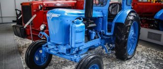
Kolyma modification of ZIL-164, nicknamed “Prosthesis”
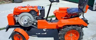
Another interesting modification of the ZIL-164 was the so-called “Kolyma” modification. It was a standard ZIL, which was converted at a local factory. During the conversion process, the truck received a third axle, which increased its load capacity and cross-country ability. It is interesting that this modernization was invented by an ordinary driver named Chumak, who independently installed a third, non-driving axle on his ZIS-150.
Seeing that this made it possible to increase the load capacity to 6 tons, the new ZIL-164 trucks began to be converted in a similar way at the local plant. The new modification had not only better maneuverability and load capacity, but also an increased service life between major overhauls. Currently, one of these miraculously preserved trucks is installed on a pedestal in Magadan. It has been there since 1980.
"Bottle 3.62 for four"
Only all these difficulties seem serious only to residents of the 21st century: the generation of the 1960s did not know more comfortable cars. Drivers loved ZIL very much. The unpretentious engine inherited many useful properties from its predecessor ZIS-5. This is a low-speed, high-torque engine that made the car very passable. And in general, these machines were simple, reliable, and, most importantly, repairable - everything was done literally “on the knee”. The only thing new to drivers was air brakes - the ZIS-150 was the first Soviet truck equipped with a pneumatic system. Everything else was familiar and accessible, and on the road the driver could fix almost any problem himself and, at least, get to the place of full repair. And the drivers remembered the firing order of the cylinders of in-line sixes (1-5-3-6-2-4): “15 magazine, bottle 3.62 for four.” This is the Soviet mnemonics.
The first exhibition of ZIL - City Day 2011. On the body is a replica of the banner from the time of construction of the Krasnoyarsk hydroelectric power station.
Export models ZIL-164
The Likhachev plant produced special export versions of the ZIL-164. These are the following models:
- ZIL-164N, which was intended for operation in temperate climates;
- For arid areas, a modification of the ZIL-164S was produced;
- ZIL-164E was intended for operation in humid and hot climates.
All export options were assembled from selected parts, because Soviet technology was supposed to bring confidence to friendly countries that there was no better Soviet technology in the world. The vehicle was distinguished not only by more powerful engines, but their load capacity was increased by 1.5 tons.
ZIL-164, which was used in the GDR, had locally produced bodies. Fire departments of the GDR had entire fleets of special fire engines made on the basis of the ZIL-164.
In the history of the Likhachev plant, several original models were recorded, which were made on the basis of the 164 model. This is a cassette cement tanker of an original design and a tanker for transporting liquefied gas.
The carrying capacity of standard modifications of the ZIL-164 was 4 tons, although if reinforced tires were installed, it could be increased by 500 kg. Dump trucks had the same carrying capacity. On dirt roads, the vehicle's carrying capacity was reduced to 3.5 tons.
Application of the machine
The use of ZIL-164 vehicles was extremely intensive. An indirect confirmation of this fact is that to date it is very difficult to find even an emergency truck of this model - the vehicles were worked until they were completely worn out.
It must be taken into account that the “finest hour” for the ZIL-164 was the end of the 50s and almost all of the 60s. This was a time when large-scale residential and industrial construction was taking place in the USSR. The need for all types of trucks was simply enormous - and in many ways it was satisfied by the “transitional” ZIL models, since the newer ZIL-130 had just begun to appear on the roads.
A significant part of these vehicles was sent to the armed forces. The army had previously used the ZiS-150, which greatly facilitated the practical development of the new truck, which had a rich “legacy” left from its predecessor - a whole family of various specialized superstructures.
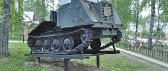
All that remains of the LAZ-690 military truck crane based on the ZIL-164
In particular, the following vehicle options were used:
- PRM-54 – mobile repair shop;
- TZ-150 – fuel tanker;
- ATs-4 – tank truck;
- APM-90 – airfield searchlight installation;
- LAZ-690 – truck crane;
- PLG-1 – mobile laboratory for testing fuel quality;
- DDA-2 – disinfection and shower unit.
In addition, ZIL-164 trucks were used as mobile command posts, vehicles for providing technical assistance and radio communication vehicles. In engineering units, “dump” modifications were widely used.
It is noteworthy that the ZIL-164 was used not only in the Soviet army, but also in the Finnish armed forces. The military sometimes called this vehicle “Zakhar” - that is, the same informal designation that was typical for the honored veteran of the Great Patriotic War, the three-ton ZiS-5 truck. Some ZIL 164 were subsequently removed from military storage and transferred to the “national economy”, and some copies were sold to private individuals.
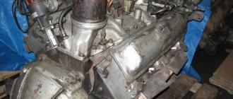
Truck engine and transmission
The standard ZIL-164 engine has a displacement of 5.5 liters. This engine was developed specifically for this model, which is why it has the same name as the truck. The engine was designed to use A-66 fuel. The peculiarity of this engine is the use of aluminum. The cylinder head is made from it. There was a water jacket around the cylinders in the block. The pistons were also made of a special aluminum alloy.
The truck's gas tank was designed to hold 150 liters of fuel. The actual gasoline consumption was about 30 liters, so the mileage at one gas station could reach 500 km.
As for the ZIL-164 transmission, the clutch on the car was of a dry type, double-disc. In 1961, a modernization was carried out, as a result of which the clutch was replaced with a single-disc one, which was intended for installation on the new ZIL-130 truck. The new clutch had a mechanical release drive and special springs that were located peripherally.
The ZIL-164 model, which was produced before 1961, was equipped with a five-speed gearbox. This box was installed on the old ZIS-150V. At the same time, fifth gear was accelerated. New gearboxes were installed on the ZIL-164A model. These are exactly the ones that were installed on the ZIL-130, which was still being finalized and was not mass-produced. The new box was reliable.
Frame, suspension and chassis ZIL-164
The frame for the truck was assembled from two spars, which were stamped from steel. They were connected to each other by powerful transverse beams using rivets. The front bumper of the car was attached directly to the frame of the car. The towing circles were also secured there. At the rear of the frame there was a special towing device designed for towing trailers and other vehicles. The ZIL-164A frame received special brackets on the frame designed for telescopic shock absorbers.
The front axle was equipped with single wheels, and the rear axle was equipped with “spark” type wheels.
Technical specifications in numbers
- Length – 6,700 m; width – 2.47 m; cabin height – 2.18 m;
- Wheelbase – 4 m;
- Ground clearance under the rear axle – 265 mm;
- Ground clearance under the front axle – 325 mm;
- Track: front wheels – 1.7 m, rear wheels – 1.74 m.
- Maximum speed – 75 km/h.
- Fuel consumption at a speed of 40 km/h is 27 liters per 100 km.
- Fuel tank capacity – 150 liters. Power reserve – 550 km.
- Curb weight – 4100 kg, gross weight – 8250 kg.
Truck steering gear and brakes
The ZIL-164 steering mechanism consists of a pair of worms or special rollers. The braking system consists of a standard pneumatically operated foot brake and handbrake. Compared to the ZIS-150, the brakes of the new model are much more effective, and the driver does not need to press the brake pedal hard. For a truck tractor, the brake system has a special dispensing valve designed to connect the trailer brake system.
ZIL-164 trucks did not become as famous as the ZIL-130. It is now almost impossible to meet them on the roads of the CIS. Sometimes single advertisements for the sale of ZIL-164 appear at car flea markets. As a rule, these specimens are prefabricated construction kits with engines from other trucks.
During its existence, ZIL-164 cars worked in all corners of the Soviet Union. That is why the truck deserves to be remembered in the history of the Russian automotive industry.