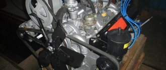
Engine TDT-40
Initially, the tractor was equipped with a D-40T engine. Diesel type: four-stroke, non-compressor, swirl chamber. The starting engine was manually activated using a cord wound around the flywheel. The engine was covered with a hood with removable sides.
Photo source: techmonuments.livejournal.com Photo TDT-40
Already in the first year of production, a new 60-horsepower diesel engine D-50 was designed specifically for this tractor, which was 10 hp more powerful than the previous model. In addition, the motor was more compact and weighed less (by 350 kg).
Here are the characteristics of the D-40T engine.
| Engine make | D-40T |
| Rated power | 40 hp |
| Maximum power | 45 hp |
| RPM | 1,500 rpm |
| Starting motor, brand | PD-10M |
The connecting rod differs in the design of the lower head. The connector of the lower head is oblique, which allows you to reduce its dimensions and, when assembling the engine, install the piston with a connecting rod on top. The connecting rod bolts are screwed into the connecting rod body and secured with steel plates.
The crankshaft, compared to the D-50 engine, has an increased diameter of the main and connecting rod journals. The crank radius has also been increased. The crankshaft is available in two production standards and eight repair sizes.
The shells for connecting rod and main bearings differ from those of the D-50 engine in diameter and completeness.
Gas distribution mechanism. The camshaft is longer than the D-50 shaft. There is no worm to drive the hour meter. The axial movement of the shaft is limited by a thrust flange bolted to the front wall of the block. To supply lubricant to the thrust flange, radial and axial drillings are made in the front journal of the shaft. There are two radial drillings on the middle journal of the shaft at an angle to each other. Through these drillings and through the channels in the block, a pulsating flow of oil flows to the transmission parts of the mechanism.
The pusher is made in the form of a cup with a spherical bottom. The point of contact of the pusher with the conical cam of the shaft is shifted relative to the axis of symmetry, due to which the pusher rotates around its axis during engine operation.
The valves have reduced diameters of the plates: for the intake one - 45 mm, for the exhaust one - 41 mm.
Lubrication system. The oil pump is driven by the crankshaft gear through an additional intermediate gear. The pump housing is bolted to the lower middle main bearing cap. The oil intake is stationary. A pressure reducing valve is installed in the pump cover, adjusted to a pressure of 5.8-6.2 kg/cm2.
The rocker arms are pressed with the help of springs to the pillars of the rocker arm rollers. The rocker arm rollers are hollow and secured in the racks using crackers and studs with nuts. The rollers are connected to each other by a coupling, through which the inside of the rollers is supplied in a common housing. Filters are connected in parallel. The oil passing through the fine filter (centrifuge) is drained into the crankcase. The coarse filter receives oil from the oil cooler. The coarse filter has two filter elements. Each of them is a corrugated glass on which a brass tape with stamped protrusions is wound. Thanks to the protrusions between the turns of the tape, gaps with a height of 0.04-0.09 mm are formed.
The filter housing contains a thermostat valve, safety valve and drain valve. The thermostat valve is adjusted to a pressure drop from 0.5 to 0.7 kg!cm2. The drain valve operates at a pressure of 2.1-2.6 kg/cm2. The safety valve is adjusted to a pressure drop of 0.5 to 0.7 kg)cm2. Normal oil pressure in the system should be within 2-3 kg/cm2.
The engine cooling system has a larger capacity (29 l), a lower number of fan shaft revolutions, a larger water radiator and a more complex water pump design than that of the D-50 engine. The upper and lower water radiator tanks are connected to the outer core plates using bolts.
Supply system. On D-40M and D-48M engines, single-plunger pumps of the ONM type or four-plunger pumps of the 4TN-8.5X10 type can be installed. In ONM pumps. a gear-type booster pump is used, and in the second case - a piston type.
The D-40L and D-48L engines are equipped with pumps of the 4TN-8.5X10 type. The power supply system of the D-40M, D-40L, D-48M and D-48L engines is equipped with a coarse filter and a fine fuel filter. The coarse filter element is similar to that of the D-37M engine. The fine filter housing contains two elements made of bankbrooch cotton yarn.
For the D-48PL engine, an additional coarse filter is installed between the tank and the booster pump. The second coarse filter (in a common block with a fine filter) is connected between the booster pump and the fine filter.
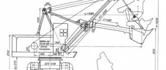
Dimensions TDT-40
| Overall length with raised loading shield | 4,500 mm |
| Overall width by tracks | 1,830 mm |
| Overall width at cabin handles | 2,014 mm |
| Overall height | 2 430 mm |
| Ground clearance | 540 mm |
| Track width | 1,480 mm |
| Base | 2,040 mm |
Specifications
The main purpose of the TDT-40 is to form a cart, load it onto the tractor shield and transport logs from the cutting area. For this purpose, the machine was equipped with a winch and a special loading device. The tractor was effective when used in off-road conditions and was widely used in logging, rafting and transport work. The tractor could also move through cutting areas with stumps, fallen trees, etc.
Photo source: nacekomie.ru The load capacity of the TDT-40 tractor is 2.5 tons
The TDT-40 tractor had a frame design. The engine and cabin were located in the front part, the rear wheels were driven. The suspension was balanced with leaf springs (there were two main balancers and four carriages). To reduce the risk of damage to the undercarriage due to excessive track tension, the guide wheels had a shock-absorbing device. If we talk about the tracks, they were small-linked with cast steel links (the latter were made of carbon steel and were heat-treated during production for greater strength).
For work in the dark, four headlights were installed on the body - two in front and two in back.
| Number of forward/reverse gears | 5/1 |
| Forward speed | 2.16 - 11.65 km/h |
| Reverse speed | 2.90 km/h |
| Winch pull | 4,350 kg |
| The volume of wood removed by a tractor in one trip | 4-6 cubic meters |
Tractor T-40
Tractor engine T-40 (D-144). Device and characteristics
The T-40 tractor is equipped with an air-cooled four-stroke diesel engine D-144 with a rated power of 50 hp.
The T-40 tractor engine consists of a crank mechanism, a fuel and air supply system, a distribution mechanism, a cooling system, an oil system and a starting device.
On the left side of the D-144 engine there are: inlet and outlet pipelines, fuel equipment and a middle deflector.
On the right side are installed: an oil centrifuge, a starter or starter, a decompressor drive mechanism, a generator, injectors and fan protection. There is an oil cooler under the fan shroud.
The front part of the power unit contains: a fan, an oil filler neck, a hydraulic pump, an hour meter, a generator and fan drive pulley. At the rear of the D-144 engine, a flywheel casing is attached to the crankcase.
D-144 engine structure : 1 - fan drive drive pulley; 2 - generator; 3 - fan; 4 — front deflector; 5 — cylinder head; 6 - nozzle; 7 — inlet pipeline; 8 — exhaust pipeline; 9- cylinder; 10 - middle deflector; 11 — flywheel housing; 12 — fuel filters; 13 — flywheel housing; 14 — oil dipstick; 15 — oil sump; 16 — connecting rod; 17 - crankshaft.
The fuel mode of the T-40 engine is regulated using a throttle disk installed in front of the protective mesh of the oil radiator and fan.
When operating the tractor in the winter, it is necessary to disconnect the oil cooler from the oil system, and secure the throttle disc with three studs in front of the fan mesh. If the ambient temperature is positive, connect the oil cooler to the system and remove the disk.
To monitor the engine temperature, use a thermometer that displays the temperature of the oil in the lubrication system.
The engine is started using an electric starter or starter. The starting system also includes a decompression mechanism and an intake air heater.
Maintenance of the T-40 tractor engine
Timely inspection and maintenance of the D-144 engine guarantees its long-term operation and minor wear of parts. To create optimal operating conditions for the crank mechanism during operation, the following is prohibited:
- Maximum load on a new or refurbished engine that has not been pre-tested.
- Cold engine load.
- Long-term operation when the engine is overloaded.
- Operating the engine with reduced oil pressure (less than 1 kgf/cm²).
- Engine overheating (oil temperature above 105º).
- Operation of the D-144 engine with low oil temperature in the crankcase (less than 55º).
- Prolonged operation of the engine at idle speed, which contributes to the occurrence of coking of the piston rings.
- Operating an engine with a missing fan shroud.
- Operation of the T-40 tractor engine with unacceptable grades of oil.
- Operating the engine without an air cleaner or when it is faulty.
Technical characteristics of the T-40 (D-144) tractor engine
| Cylinder diameter and piston stroke, mm | 105/120 |
| Number and arrangement of cylinders | 4p |
| Cylinder displacement, l | 4,15 |
| Nominal torque reserve factor, % | 15(-3,+10) |
| Relative oil consumption for waste versus fuel consumption, % | 0,3-0,5 |
| Diesel weight as delivered, dry, kg | 375-390 (depending on configuration) |
| Overall dimensions, mm. (length Width Height) | 919x741x848 |
crank mechanism
The crank mechanism (CPM) is designed to convert the reciprocating motion of the pistons into the rotational motion of the crankshaft. Gas pressure forces generated during combustion of fuel in the cylinders act on the pistons. The force is transmitted to the crankshaft crank through a connecting rod, pivotally connected to the crankpin and the piston. The flywheel mounted on the crankshaft is designed to reduce engine unevenness and transmit torque to the tractor transmission through the clutch.
To ensure normal operation of the crank mechanism during operation, the following is not allowed:
1. cold engine load;
2. long-term operation on a loaded engine;
3. engine operation with oil pressure less than 0.15 MPa (1.5 kgf/cm²);
4. engine operation when the oil temperature in the line is less than 40 ºC and above 120 ºC;
5. prolonged engine idling, causing coking of the piston rings;
6. engine operation with a missing fan casing;
7. engine operation on unsuitable types of oils;
8. engine operation without an air cleaner;
9. engine operation with interruptions, suspicious knocking and exhaust.
Crank mechanism: 1 - fan drive drive pulley; 2 - special bolt; 3 — oil pump drive gear; 4 — distribution drive gear; 5 — connecting rod bearing shell; 6 — connecting rod: 7 — piston; 8 — oil scraper ring: 9 — compression rings; 10 — main bearing shell; 11 - flywheel; 12 — cuff; 13 - ball bearing; 14 — rear oil deflector; 15 — connecting rod bolt nut: 16 — crankshaft; 17 — counterweight; 18 — front oil deflector.
T-40 tractor engine repair
To repair the engine, it is necessary to disassemble it and clean the cavities of the crankpins. To do this, pull out the cotter pins and unscrew the screw plugs.
The effectiveness of centrifugal cleaning of oil in the cavities of the connecting rod journals largely depends on compliance with all rules of maintenance of the lubrication system, as well as on proper storage of oil and its filling into the engine. If the recommended rules are not followed and violated, the cavities of the connecting rod journals will soon fill with deposits and oil purification in them will cease.
Engine repair is necessary when starting is difficult, there is a drop in power, the oil pressure drops below the established norm, there is heavy smoke and gases escaping, when suspicious knocking sounds occur, or when the crank mechanism is faulty. The engine is disassembled indoors.
The disassembled engine is checked and inspected based on what malfunctions were observed during its operation. For example, if the engine smoked heavily, consumed a large amount of oil, there was a drop in power, or it was difficult to start, it is necessary to check the condition and degree of wear of the piston rings, cylinders and pistons.
If the pressure sensor showed low or zero oil pressure in all operating modes, then before disassembling the engine it is recommended to check the sensor itself and the cleanliness of the oil receiver mesh, as well as the serviceability of the pressure reducing valve of the oil pump and centrifuge. Only after these checks can you begin to disassemble the main and connecting rod bearings to troubleshoot and repair the engine.
06.03.2022
Modifications
In 1961, a modification was introduced, which received the TDT-40M index and was even more popular than the original version. The car can be called a transitional “link” between the TDT-40 and the TDT-55, which was later launched into production. Changes include a more powerful engine (model D-48T) and the presence of a hydraulic device for dropping the loading shield. The new four-cylinder four-stroke engine had a vortex-chamber mixture formation function and developed up to 48 hp. at 1,600 rpm. Specific fuel consumption - 205 g/l. With. h. The launch was carried out from the PD-10M starting engine.
In addition, the tractor had improved dynamic properties (this was achieved by shifting the center of gravity forward) and was equipped with a reinforced frame.
Engine 40DM (12DRN 23/30)
Description of the design of the 12DRN 23/30 engine
The 40DM engine (designation according to GOST 12DRN 23/20) is a V-shaped twelve-cylinder reversible two-stroke engine with direct-flow valve scavenging and a two-stage pressurization system with intermediate air cooling.
The engine block is a V-shaped steel welded structure, divided by transverse racks (beams) into six sections. The crankcase is covered from below with a thin-walled pan (bathtub). The diesel engine does not have a foundation frame. The crankshaft is suspended from the crankcase on seven steel hangers, which are bolted to the transverse beams of the block. Thin-walled steel main bearing shells are filled with lead bronze. The middle of the seven main bearings is a mounting bearing and differs from the others in its larger length and the presence of thrust collars. Cast iron cylinder inserts of the “wet” type are cooled in the upper part with water, and in the area of the purge windows - with air. Each bushing is attached to the cylinder cover with six studs screwed into the upper collar of the bushing, and, assembled with the cover, is inserted into the cylinder block socket. This design ensures unloading of the gas joint of the bushing, which is sealed with an annular red-copper gasket. The cylinder covers are composite, consisting of a cast iron bottom and an aluminum top. Each cover and bushing assembly is secured to the cylinder block with four studs. Through 8 bypass holes in the bottom of the cover, water flows from the cylinder liner into the cooling cavity of the cover. The cover contains a nozzle, four outlet valves and a start valve with an indicator valve. The cylinder covers are closed on top with caps that prevent splashing of the oil that lubricates the distribution mechanism. The crankshaft is made of alloy steel. The surfaces of the shaft journals are nitrided. The wedge angle of the six cranks of the shaft is 60°. The cranks operate in the following order: 1-5-3-4-2-6. All crankshaft journals have internal bores, and the bores of the connecting rod journals are made eccentrically relative to the working surface. There are holes in the crankshaft body through which oil flows from the main bearings to the connecting rod bearings, bypassing the internal cavities of the shaft journals. At the nose end of the crankshaft, a splined bushing of the torsion shaft of the positive displacement supercharger drive is fixed and an anti-vibrator is installed, designed to reduce the stresses arising in the crankshaft due to torsional vibrations. At the rear end of the shaft there is a power take-off flange and a camshaft drive gear. The connecting rod mechanism (each of the six knees) consists of a main and a trailing connecting rod, connected to each other by a pin installed in the eyes of the lower head of the main connecting rod. The connecting rods are made of high quality alloy steel. The connecting rod rods have an I-section with a thickening in the middle part for the oil channel. Steel bushings with a thin layer of lead bronze are pressed into the upper heads of both connecting rods and into the lower head of the trailing connecting rod. The split lower head of the main connecting rod has thin-walled steel connecting rod bearing shells filled with lead bronze. The removable lower head cover is secured to the main connecting rod rod with four connecting rod bolts. The pistons consist of three main parts: a head made of high-strength cast iron, a crown made of pearlitic cast iron and an insert made of aluminum alloy. The trunk is attached to the head with screws. The axial movement of the insert is limited by a spring ring installed in the lower part of the throne on the inside. The piston head has four cast iron sealing rings with bronze bands on the working surface. At the bottom of the trunk there are two oil scraper rings, which simultaneously prevent air from flowing from the receiver through the purge windows into the engine crankcase. The floating piston pin is made of alloy steel and is mounted in steel bushings filled with lead bronze, pressed into the piston insert. The pistons are cooled by oil coming from the upper heads of the connecting rods. Oil flows into the cavity between the insert and the bottom of the piston head through a hollow cylindrical slider, tightly pressed by a spring to the upper head of the connecting rod. The seven-bearing camshaft is located in the camber of the cylinder blocks and is driven by a gear transmission from the rear end of the crankshaft. Knuckle washers (two for each pair of cylinders) are made of carbon steel, have a case-hardened and hardened working surface and are hot driven onto the shaft using keys. In addition to the camshaft, the exhaust valve drive mechanism includes struts with levers (rocker arms), crossbars with hydraulic pushers and a pusher with rods. A block twelve-plunger high-pressure fuel pump (HPF) is installed in the engine camber above the camshaft and has its own cam shaft in its housing. This fuel injection pump is of the spool type with fuel supply regulation at the beginning and end. Fuel from the supply tank flows through a coarse strainer to a reversible gear fuel priming pump (which has two sets of suction and discharge valves. The pump gears are driven into rotation from the nose end of the crankshaft. From the fuel priming pump, fuel is supplied at a pressure of about 0.4-0. 5 MPa through a fine felt filter to the injection pump and then under high pressure to the nozzles installed in the center of each cylinder cover. Closed type nozzles are adjusted to a needle lifting pressure of 31.4 MPa. The nozzle nozzles have 7 nozzle holes with a diameter of 0. 4 mm. Diesel air supply units are located at the nose end of the engine and consist of two freely rotating gas turbochargers (one for each cylinder block) and a drive positive displacement supercharger. Gas turbochargers (turbochargers) of the I2TK brand are used as the first stage of air compression. The air is compressed in a centrifugal compressor, the wheel of which was driven into rotation by an axial single-stage gas turbine, powered by the energy of diesel exhaust gases. The gases exhausted in the cylinders of each diesel unit are supplied to the turbine through two branches of a divided exhaust manifold. The upper branch is connected to the 1st, 2nd, 3rd cylinders of the blocks, and the lower branch is connected to the 4th, 5th and b-m. A driven reversible volumetric rotor-blade supercharger is used as a supercharger for the second stage of air compression. An air cooler is located between the two compression stages. The drive supercharger has helical three-bladed rotors made of aluminum alloy. The rotors are driven through a single-stage gear intensifier from the nose end of the crankshaft. The transmission includes an elastic gear, torsion shafts and an elastic rubber-metal coupling. To maintain the required direction of air flow when reversing the diesel engine, spools moved by servomotors are installed at the inlet and outlet of the drive supercharger. The diesel oil system provides oil supply to the rubbing surfaces, cooling of the rubbing surfaces, cooling of the engine pistons, and operation of the diesel hydraulic control system. The reversible gear-type oil pump has injection and pump-out sections made in one housing. The pump is located in the lower part of the nose end of the engine and is driven into rotation by the elastic drive gear of the positive displacement air blower. The pressure section of the pump sucks oil from the tank and delivers it through a coarse strainer to the rubbing surfaces of the diesel engine, in particular, to the main bearings of the crankshaft, then through the drillings in the hall - to the connecting rod bearings and through the holes along the connecting rod rods - for lubrication of the head bearings and for cooling the pistons. The pump's pumping section takes oil from the engine crankcase sump (bath) and directs it through the thermostat and oil cooler into the tank. Depending on the temperature of the oil, the thermostat can transfer it into the tank past the cooler. A centrifugal fine oil filter is installed on the tank, through which part of the oil supplied by the discharge section of the pump passes. The diesel cooling system includes a fresh water circuit designed to cool the cylinder liners and covers, exhaust manifolds and gas turbines of the engine, and a sea water circuit designed to cool the purge air (in the air cooler), oil (in the oil cooler) and fresh water (in water cooler). Centrifugal pumps of both circuits, identical in design, are installed on the nose end of the engine and are driven by the elastic gear of the multiplier of the volumetric air blower. Radial wheel blades and casing design ensure identical pump operation in any direction of wheel rotation. The closed fresh water circuit contains a thermostat, which, depending on the temperature of the water leaving the diesel engine, directs it either to the water-to-water cooler or past the cooler to the pump. The diesel engine is started with compressed air under a pressure of about 3-4 MPa. Start valves are installed only on six cylinders of the engine (on the cylinders of the main connecting rods block). The air distributor is connected to the cam shaft of the fuel injection pump. A hydropneumatic type reversing device is located at the rear end of the diesel engine. This device allows you to move the camshaft, air distributor shaft, injection pump shaft and spools of the drive air supercharger from the position corresponding to the diesel engine operating in the “forward” direction to the position corresponding to the operation in the “backwards” direction, or vice versa. This movement is carried out by rotating the air distributor shaft and the high pressure fuel pump at an angle of 60° relative to the diesel crankshaft in the direction of their previous rotation and the camshaft at an angle of 36° against the direction of its previous rotation. The digplem control post is installed at its aft end. The post mechanism (the steering wheel and the fuel injection pump rack control sector) provides the necessary sequence and consistency of starting, stopping and reversing, and also makes it possible to change the diesel engine speed throughout the entire operating range and perform an emergency engine stop. The diesel engine is equipped with an all-mode isodromic centrifugal speed controller with an oil servomotor and its own oil system. The regulator automatically maintains a given crankshaft speed, changing the fuel supply to the cylinders in accordance with changes in load. The rotation speed is changed by changing the tension of the governor spring. Changing the fuel supply to the cylinders is carried out by moving the fuel injection pump racks using the regulator servomotor. The regulator is located in the nose of the engine camber and is driven by the camshaft. When the diesel engine speed increases above the maximum permissible (870 ± 10 rpm), the limit regulator is activated, bringing the fuel injection pump racks to zero flow and stopping the engine. The limit regulator is installed in the rear part of the cylinder camber, above the reversing device. Starting the diesel engine is possible only after cocking the limit regulator lever. Basic technical data of the 40DM diesel engine.
Diesel 40DM is intended for installation on ships to operate on a propeller.
A diesel engine of the right model is installed in the laboratory of the SDVS and DU of the St. Petersburg State Medical University (the crankshaft rotates clockwise when the engine is running in the “forward” direction, if you look at the diesel engine from the side of the power take-off flange). Number of diesel cylinders…………………………………….. 12 Cylinder diameter…………………………………………….. 230 mm Stroke of the main connecting rod……… ……………………….. 300 mm Stroke of the piston of the trailing connecting rod……………………………. 304.3 mm Rated speed …………………………… 750 rpm Rated power at rated speed ……………………………………………………….. 1618 kW (2200 l .s.) Maximum rotation speed………………………….. 780 rpm Maximum power at maximum rotation speed……………………………………………………….. 1839 kW (2500 hp) Average effective pressure: at rated power…………………………………… 0.866 MPa (8.83 kgf/cm2) at maximum power…………………………………… …….. 0.952 MPa (9.70 kgf/cm2) Average piston speed: at rated speed……………………….. 7.5 m/s at maximum speed………………… …… 7.8 m/s Minimum stable rotation speed when operating according to the screw characteristic………………….. 300 rpm Weight: diesel engine with attached auxiliary units without water and oil…………………………… ….. 9750 kg of water in a diesel engine………………………………………………………….. 150 kg of oil in a diesel engine……………………………………… …….. 160 kg Dimensions: length…………………………………………………………….. 3725 mm width…………………………………………………… ………………………… 1730 mm height……………………………………………………………. 2190 mm Valve distribution phases of a cold diesel engine
Beginning of opening of the exhaust valves ovk = 90° to BDC.
End of closing of exhaust valves svk= 52° after BDC. Beginning of opening (end of closing) of purge windows opo = zpo = 46° before (after) BDC. Control indicators of diesel engine operation at rated power
Exhaust gas temperature of individual cylinders is not higher than………………………. 793 K (520 C) Gas temperature difference between individual cylinders is not more than…………………………….. 100 K Cooling water temperature: at the diesel engine outlet is not higher than……………………………… ………………………………. 358 K (85°C) at the diesel inlet not lower than …………………………………………………………………. 333 K (60°C) Circulating oil temperature: at the outlet of the diesel engine is not higher than…………………………………………………………………………………. 358 K (85°C) at the diesel inlet not lower than…………………………………………………………………………………318 K (45°C) Maximum gas pressure in cylinders Pz not higher than 10.8 MPa (110 kgf/cm2) The difference in maximum pressure Pz for individual cylinders is not more than………….. 0.78 MPa (8 kgf/cm2) Oil pressure for lubrication of crankshaft bearings is not lower than……… ………….. 0.42 MPa (4.3 kgf/cm2) Purge air pressure (excess) about……………………………………. 0.1 MPa (1.0 kgf/cm2) The exhaust gas pressure at the outlet of turbochargers is not higher than………………. 0.016 MPa (120 mmHg) Specific effective fuel consumption about…………………………………………….. 238 g/kW*h (175 g/l.s*h. ) Specific effective air consumption about…………………………………………….. 7.89 kg/kW*h (6.8 kg/l.s*h.)
Cross and longitudinal sections of the engine
: