29.04.2021
The electrical equipment of the mini loader is used to provide power to the electrical systems of the machine and perform the corresponding functions. Electrical equipment includes sources of electrical energy and devices that consume it - these are:
- batteries (batteries) located on the left and right wings (the battery installed on the right wing, when the mini-loader is delivered from the factory, is dry-charged);
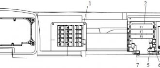
- a control instrument system consisting of a left (Figure 1), right (Figure 2) panel;
- lighting system, sound and light signaling (road lights, front/rear work lights, front/rear signal lights, cabin lights, flashing warning light, front/rear flashing light).
Figure 1 - Left panel 1 - indicator lamp for dirty drain oil filter; 2 - indicator lamp for the minimum level of working fluid; 3 — portable lamp socket; 4 — air heater fuse box; 5 - indicator lamp for contamination of the pressure oil filter; 6 — control lamp for turning on the flashing light; 7 — fuse block; 8 — indicator lamp for turning on the working headlights; 9 — hydraulic system oil temperature indicator receiver; 10 — mini-regulator of operating modes of the air heater; 11 — control lever; 12 — switch for turning on working headlights; 13 — alarm switch; 14 — fuel level indicator receiver.
Operation of the MKSM-800 hydraulic system
When the mini loader motor is started, and the levers (1) (Figure 1) and (5) correspond to the “neutral” position, the pump (28) (Figure 2) of the functional equipment begins to pump working fluid from the tank (29). After passing through the pressure filter (32), it reaches the pressure section of the distributor (36). When the spools (38) of the distributor (36) are in the neutral position, the work of the primary overflow fuse (35) is to connect the pressure and return hydraulic lines to each other. Due to this, the liquid will flow from the pressure section of the distributor (36) to the inlet of the drain filter (24). Then it reaches the suction cavity of the pump (19), which feeds the volumetric hydraulic drive. When the pressure in the suction cavity reaches a value corresponding to the setting value of the valve (26), it will open, and the excess working fluid will flow back into the tank (29).
Figure 1 — Controls 1 — motion control lever;
2 — control pedal for replaceable attachments; 3 — friction clutch pedal; 4 — fuel pedal; 5 — operating equipment control lever; 6 — manual fuel supply handle; 7 - protective lever. Each of the MKSM-800 pumps (19), through its pressure outlet, supplies working fluid through feed channels into the suction cavity of the pump (20). When the pressure inside the suction cavity corresponds to the settings of the valve (18), it will open, excess liquid will drain into the hydraulic pump housing (10), (17). From there, through the drainage line, it goes inside the radiator (21), drain filter (24), tank (29). If the radiator creates a lot of resistance, the valve (22) opens and part of the liquid is drained back into the tank. From the pressure outputs of two hydraulic pumps (19), the liquid is supplied respectively to the valves (11), which are responsible for the operation of the travel and brake locking mechanism and (16), which ensures the locking of the travel and functional equipment.
Hydraulic system operation diagram
When the safety lever (7) (Fig. 1) is raised, the valves (11) (Fig. 2), (16) move to the left as shown in the figure. In this case, the pressure outputs of the feed pumps (19) are disconnected from the hydraulic pump control mechanisms (10, 17), which are connected to the tank drain line (29). As a result, the axial piston pumps (20) switch to idle mode, which eliminates the possibility of the MKSM-800, MKSM-1000 mini loader moving when the control lever (1) is accidentally pressed (Figure 1).
Figure 2 - Diagram of the hydraulic system 1 - plug; 2- quick release coupling; 3 — block of secondary make-up and safety valves of the bucket “pull” (18 MPa); 4 — block of secondary make-up and safety valves of the bucket “pull away” (5 MPa); 5- bucket hydraulic cylinder; 6 — block of secondary make-up and safety valves for boom lift (18 MPa); 7 — boom valve; 8 — boom hydraulic cylinder; 9 — block of secondary make-up and safety valves for lowering the boom; 10.17 - hydraulic pump; 11 — brake and travel blocking valve; 12.14 - hydraulic motor; 13 — safety valve (36 MPa); 15 — low pressure line valve; 16 — valve for blocking travel and working equipment; 18 — control pressure valve; 19 — feed pump; 20 - axial piston pump; 21 - radiator; 22 - valve (170 kPa); 23 - valve (200 kPa); 24 - drain filter; 25.33 — contamination sensor; 26 - valve (20 kPa); 27 — temperature sensor; 28 - pump; 29 — hydraulic tank; 30 — level sensor; 31 - valve (0.65 MPa); 32 - pressure filter; 34 — blocking valve; 35 - primary safety overflow valve (16 MPa); 36 — distributor; 37, 39 — check valve; 38 — spool; 40.41 - block of secondary make-up safety valves (18 MPa).
Hydraulic oil cooling
Cooling of the MKSM-800 working fluid is ensured when it is discharged from the drain line through the valve (15) into the radiator (21). The speed and direction of movement of the loader are determined by moving the control lever (1) (Fig. 1).
To control the operation of the main equipment, a lever (5) is used (Fig. 1), and a pedal (2) is used for replaceable attachments. When exposed to them, the spools 38 (Fig. 2) of the distributor (36) move, and the overflow fuse (35) goes into operating mode (the pressure line is disconnected from the drain).
Fluid is supplied to the skid steer functional equipment by means of a pump (28), which directs it through the pressure section of the distributor (36), the check valve (37) and the corresponding spool (38). She can do:
- raising the boom – to the cavities of the hydraulic cylinders (8);
- displacement of the bucket “away from itself” – towards the cavities of the hydraulic cylinders (5);
- operation of replaceable attachments - to the quick-release couplings (2) (to the right - pedal travel (2) (Figure 1) forward and to the left - pedal travel back).
Protection of the loader elements from overload when the spools are in the operating position is carried out through the primary overflow fuse (35). When the spools are located in the neutral position, the working units are protected from overloads by means of secondary make-up fuses.
Hydraulic motor MPA 33 (MKRN.382213, VMIZH.063144)
The hydraulic motor MPA 33 (MKRN, VMIZH, YUFEI) is an axial piston hydraulic motor with an inclined fixed plate. On MPA 33 there is a valve block, the main task of which is to distribute the flow of hydraulic oil and protect the transmission circuit from overloads. The hydraulic oil, which enters the motor housing through the safety valves, is replenished by the filling pump, which is part of the NPA 33 pump. The safety valves located on the valve block are set to the same pressure - 35 MPa. In order for the oil to be drained from an unloaded branch, a spool is built into the valve block. The release of oil for draining and flushing of the hydraulic drive is carried out by a bypass valve, which is adjusted 0.2 MPa lower than the bypass valve of the hydraulic pump NPA 33. The oil that goes to drain is flushed by the housing of the hydraulic motor. The valve block is located at the top of the hydraulic motor and is shaped like a cube. The hydraulic motor itself is attached to the final drive of the loader through the brake cover.
Controls and instrumentation MKSM-800
To control the movement of the MKSM-800 or MKSM-1000 loaders, their main and replaceable equipment, levers and switches are used, located inside the driver’s cabin. It is designed taking into account the requirements of ergonomics and the ability to control all functions of the MKSM.
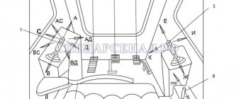
Figure 1 — Controls 1 — motion control lever; 2 — control pedal for replaceable attachments; 3 — friction clutch pedal; 4 — fuel pedal; 5 — operating equipment control lever; 6 — manual fuel supply handle; 7 - protective lever.
Specifications
- Load capacity/total weight – 800/2800 kg
- Engine name – 5201.22
- Engine parameters - diesel, 3 cylinders, 46 l. pp., developer – Zetor
- Speed – 10 km/h (maximum)
- Ground clearance – 205 mm
- Dimensions, mm: 3270/1680/2065
- The height of the bucket suspension point is 3060 mm
- Fuel tank capacity – 55 liters
- Unloading height – 2410 mm
- Front/rear track – 1410 mm
- Climbing angle – 13 degrees
- Turning radius – 2440 mm
- Seat – yes
- Working body/chassis – bucket/wheels.
Right Panel Controls
With his right hand, the operator-driver can influence:
- lever (5) (Figure 1) for controlling the main equipment, it can have the following positions:
- forward (E) – the boom lowers;
- back (G) – the boom rises;
- to the right (I) – the bucket tips away from itself;
- to the left (K) – the bucket tips over onto itself.
- battery switch pos. 2 (Figure 2), after completing work on the mini-loader, the switch must be turned off;
Figure 2 - Right panel 1 - switch for turning on headlights; 2 — battery switch; 3 — switch for turning on the cabin glass washer; 4 — operating time counter; 5 — sound signal button; 6 — control lamp for turning on the direction indicators; 7 — direction indicator switch; 8 — temperature sensor; 9 — operating equipment control lever; 10 — switch for turning on the starter and instruments; 11 - light indicator of engine operation; 12 — light indicator of battery discharge; 13 — light indicator of emergency oil pressure in the engine; 14 — light indicator of emergency temperature of the engine cylinder head; 15 — light indicator of air filter contamination; 16 — light indicator for engine preheating.
Important: the battery switch must be turned off no earlier than 4-5 minutes after turning off the heater
- switch (1) for road lighting (in parallel with the lights, the sidelights, license plate lights, and instrument lighting light up);
- switch (3) for the mini loader cabin glass washer (the washer will operate as long as the switch is held in the “On” position);
- sound signal button (5);
- turn signal switch (7) (when the switch is on, the control indicator (6) will flash).
In addition, with the right hand the operator operates the handle (6) (Fig. 1) of the manual fuel supply drive. The handle positions can be as follows:
- all the way forward - fuel is not supplied at all; all the way back – maximum fuel supply.
Adjusting KAMAZ valves with a Cummins engine
Cummins engines, which are now installed on KAMAZ vehicles, are very reliable and have a long service life. They require mandatory regular maintenance. Among other things, periodic adjustment of KAMAZ valves is extremely important. The automaker's official instructions indicate that valve adjustment in KAMAZ vehicles with a Cummins engine should be carried out after a minimum of 240,000 km. But, in addition to performing planned work, the need for it may arise for other reasons.
The first signs indicating that adjustment of the KAMAZ internal combustion engine valves is necessary is a knocking sound that occurs under the hood, an increase in the “appetite” of the power plant or a decrease in its power. Ignoring these signs and lack of timely valve adjustment leads to the fact that subsequent use of the engine may lead to new malfunctions in the internal combustion engine. Therefore, it is worth knowing the procedure for adjusting KAMAZ valves yourself.
Why does valve imbalance occur?
It is necessary to realize that adjusting KAMAZ valves with your own hands is useless if the original cause of the malfunction is not eliminated. Possible causes are breakdowns that are associated with improper or not carried out on time maintenance:
- incorrect setting of valve clearances or incorrect sequence of tightening bolts on the cylinder head during preliminary engine maintenance;
- physical wear or malfunction of timing parts;
- the use of low-quality cooling fluid, which led to overheating of the engine;
- a faulty air filter that allows not only air but also dirt to enter the cylinders;
- the use of contaminated or low-quality motor oil, untimely replacement of the filter or the oil itself;
- fuel that does not burn completely due to other breakdowns or poor quality of the fuel itself.
Procedure for adjusting KAMAZ valves with a Cummins engine: clearances
The procedure for adjusting KAMAZ valves and the procedure for adjusting KAMAZ valves with a 6-cylinder Cummins engine do not differ from each other.
Adjusting KAMAZ Euro-4 valves involves first removing the rocker cover from the engine. To do this, you need to disconnect the crankcase breather from this cover. First, remove the oil drain lines from the breather.
Right control panel
The right panel of MKSM-800 has an indication and control unit, on which is located:
- switch (10) for starting the starter and turning on the devices; it has three positions:
- neutral;
- I fixed – launch of electrical devices and systems;
- II return – starting the starter.
- a number of indicator lights:
- (11) – indicating a running motor;
- (12) – signaling that the battery is low;
- (13) – signaling insufficient oil pressure in the engine;
- (14) – indicating the critical permissible temperature of the engine cylinder head;
- (15) – signaling that the air filter is heavily soiled (indicates the need to clean or replace it);
- (16) – informing about the need to preheat the engine at an external temperature of less than 0°C.
In addition, on the right panel of the mini-loader there is an operating time counter (4) (Fig. 2), which calculates the engine operating time in hours. The maximum capacity of the counter's reading mechanism is 99999.9 hours. It is made in the form of a device that combines a clock mechanism and an electromagnetic relay that starts and stops the clock mechanism.
Where is it located, how to check and replace
Replacing this part is not at all difficult, but some features of performing such work should be known before starting repair operations. First of all, it is necessary to accurately determine the location of the fan switch sensor, dismantle it and check the condition of this part.
The DVV is located under the generator on the right side of the engine. To remove the sensor, you must use an extended socket wrench, but first disconnect the electrical wires for this part.
Before removing the sensor, place a wide container under the engine to collect coolant leaking from the engine.
When the sensor is dismantled, it is checked. For this purpose, it is enough to use a multimeter that is set to ringing or resistance measurement mode. In the absence of heating, the part should not pass electric current through itself.
After placing the sensor in a container of boiling water and waiting a couple of minutes, it is removed and the resistance is immediately measured. When heated, the sensor contacts close, which will be reflected on the display of the digital measuring device.
If a malfunction is identified, a new one is installed in place of the removed part, the contact wires are connected, coolant is poured into the engine to the required level, and the functionality of this element is checked directly on the car. When the antifreeze heats up to approximately 85 degrees Celsius, the sensor contacts should close and the cooling system fan will start working.
Left Panel Controls
With the left hand, the operator-driver can work with:
- lever (1), responsible for controlling movement (Fig. 1); this lever can be in the following positions:
- forward (A) – move forward;
- back (B) – move backward;
- right (D) – turn right;
- right forward (AD) – turn right forward;
- left forward (AC) – turn left forward;
- right back (R) – turn left back;
- left back (BC) – turn right back;
- switch (13) (Fig. 3), used to turn on the hazard warning lights (when it starts, the turn signal lamps and control indicators (6) (Fig. 2) of the right panel will flash);
- switch (12) (Figure 3), used to turn on the work lights (when it is turned on, the indicator lamp (8) will light up);
- mini-regulator (10) designed to turn on the air heater.
Figure 3 - Left panel 1 - indicator lamp for dirty drain oil filter;
2 - indicator lamp for the minimum level of working fluid; 3 — portable lamp socket; 4 — air heater fuse box; 5 - indicator lamp for contamination of the pressure oil filter; 6 — control lamp for turning on the flashing light; 7 — fuse block; 8 — indicator lamp for turning on the working headlights; 9 — hydraulic system oil temperature indicator receiver; 10 — mini-controller for operating modes of the air heater; 11 — control lever; 12 — switch for turning on working headlights; 13 — alarm switch; 14 — fuel level indicator receiver. In addition, the left panel has the following indicator lamps:
- (1) – indicator of contamination of the drain oil filter;
- (2) – signals the minimum level of working fluid;
- (5) – indicator of contamination of the pressure oil filter;
- (6) – indicator for turning on the flashing light;
- (8) – indicator for turning on the working lights.
In addition to indicator lamps, the panel has:
- socket (3) into which you can plug in a portable lamp;
- fuse box (4) for the air heating system;
- fuse box (7) (the purpose of the fuses is described in table 9.2);
- fuel level gauge receiver (14);
- temperature gauge receiver (9) for oil in the hydraulic system.
Mercedes Actros valve adjustment
The valve group is the final gas distribution link. It includes the valve, spring, mounting parts, guide sleeve and valve seat.
The valve group operates at high temperatures and heavy loads. The valve-seat interface is particularly stressed. These parts are maximally exposed to shock and elevated temperatures. Due to the difficult conditions in which the valve group operates, the following requirements are imposed on it:
- valve closure must be tight;
- the parts must have a good streamlined shape;
- all elements must be highly wear-resistant and corrosion-resistant;
- all elements must have a minimum mass;
- the material from which the parts are made must be high-strength and rigid;
- There must be efficient heat removal from the exhaust valve.