Magneto M149A T-170, T-130, B-10
On our website there is a lot of useful information about tractor units and assemblies, such as: attachment units - blade T-170, T-130, B-10, tractor drive and power plant engine D-160, D-180, housing lining and tractor driver's workplace, cabin T-170, T-130, final drive and caterpillar undercarriage T-170, T-130, B-10, as well as caterpillar bogies and rollers located on them T-170, T-130, B -10, spare parts for tractor units, spare parts T-170, T-130, B-10, useful information is written in the T-170 repair instructions.
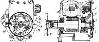
Rice. 5.116. Magneto M149A
If cracks, broken housings, a weak spark, its absence or interruptions in spark formation are detected, the magneto should be removed from the starting motor and routine repairs should be carried out or it should be replaced.
Magneto repairs should be carried out in specialized workshops.
If spare assembly units and parts are available, magneto repairs can be carried out at the site of operation by replacing failed ones.
Removing the magneto
Disconnect the high voltage wires from the magneto distributor and wire thirteen from the magneto ignition switch terminal.
Unscrew the three nuts and remove the magneto from the starter motor timing gear housing.
Magneto disassembly
Unscrew nut 15 (see Fig. 5.116) and remove the starting accelerator 17 from the cone of the rotor shaft 33. Knock out the segment key 16 from the keyway of the rotor shaft.
Unscrew the two screws 26 and remove the housing 24 with the screen cover 25 and the distributor cover 27 with contacts 23 and 28 from the magneto cover 32.
Unscrew screw 30 two or three turns and remove slider 29 from cam 5.
Unscrew screw 9 securing the terminals of capacitor 22 and transformer 18. Unscrew screws 31 and remove the magneto cover with breaker plate 8 from the magneto body 34.
Remove the rotor shaft with bearings and cam from the magneto housing. Unscrew screws 19 five to seven turns and remove the transformer from the magneto housing.
Checking the technical condition and repairing magneto parts
Inspect the magneto housing and cover with the breaker plate, the slider and the distributor cover.
If there are cracks or chips in the magneto housing, the magneto should be replaced. Scratches and traces of corrosion on the surfaces of the pole shoes should be cleaned with sandpaper. If a thread in the magneto housing is broken, it is allowed to cut a repair size thread.
Wipe the working surfaces of contacts 12 of the breaker with nylon tape or suede soaked in gasoline. If the contacts burn, they should be cleaned with a special file or a flat needle file, followed by grinding.
The pressure of the breaker spring on the contacts should be checked with a spring dynamometer. If the spring pressure (at the moment of contact separation) is less than 5-7 N (0.5-0.7 kgf), then the ultrasonic breaker lever with the spring should be replaced.
If it is necessary to replace the contacts, unscrew the screw 10 securing the breaker spring, remove the lock washer 14 from the axis of the breaker plate 8, the breaker lever with the spring and contact, and, having unscrewed the screw 11, remove the contact post.
If cracks and chips are found on the magneto/distributor covers and slider, as well as if there is an electrical breakdown of the distributor, they should be replaced.
The burnt working surfaces of the contact carbon and the runner electrode should be cleaned. Inspect the rotor and check its magnetization. Scratches and traces of corrosion on the surfaces of the pole pieces should be cleaned with sandpaper.
If the inner rings of the bearings do not fit tightly on the rotor shaft (the permissible diameter of the shaft surfaces for the inner rings must be at least 14.97 mm), or the thread under the accelerator fastening nut is broken, the rotor shaft must be replaced.
The rotor magnetization should be checked with an MD-4 magnetometer. If the rotor magnetization is less than 200 μWb, then carry out its magnetization using the NA-5-VIM apparatus.
Replace the starting accelerator if its spring is damaged. If necessary, wash the starting accelerator in clean gasoline, then dry it or blow it with compressed air. After this, lubricate it by immersing it in a mixture of 50% turbine and 50% industrial oil.
Inspect the bearing rings and cages. If traces of metal chipping are detected on the rings and rolling elements, bent, or cracks on the cages, the bearings should be replaced.
Check the capacitor and transformer on the KI-968 stand. If a capacitor breakdown, open circuit or transformer breakdown is detected, they should be replaced.
Burnt transformer electrodes should be cleaned.
Magneto assembly and adjustment
Wash the rotor shaft bearings in gasoline, dry them and fill the separators 2/3 full with CIATIM-201 lubricant.
The cone, lamellas and threads of the rotor shaft, the ends of the transformer core, and the screws securing its terminals should be lubricated with technical petroleum jelly.
The rotor and pole shoes of the magneto should be lubricated with a thin layer of CIATIM-201 grease.
Wash the felts and cords in gasoline, soak them in turbine oil and squeeze them out.
Install transformer 18 (see Fig. 5.116) into the magneto housing 34 and secure it with two screws 19. In this case, contact 7 must be pressed by its spring to the transformer terminal.
Check and, if necessary, adjust the gap B = 6.5-7 mm between the transformer electrode 21 and the housing arrester 20 by bending the transformer electrode.
Design features
To dampen vibrations produced by the D-160 engine when operating at a rated speed of 1250 rpm, a balancing mechanism is installed. It is located on the lower plane of the block and is hidden by the crankcase. The lubrication of the bearings of this mechanism is centralized, but the teeth of its wheels are lubricated by oil mist that forms in the internal chamber of the motor.
Another design feature is the presence of a decompression mechanism. It opens the intake valves of the cylinder head during engine starting, adjustments or during an emergency stop. Thanks to its operation, the crankshaft does not encounter resistance and rotates freely. The valves are opened by decompressor rods, which act on them by turning the mechanism shaft.
Installing a magneto on the starting motor and installing the ignition on the starting motor.
. To install the magneto on the starting motor, remove the clutch hatch cover. While turning the crankshaft of the starting engine, install the flywheel so that the “ВМТ-1Ц” mark on the end of the flywheel coincides with the mark on the flange of the clutch hatch (Fig. 25, a). In this case, the mark on the magneto drive shaft should coincide with the “M” mark on the flange of the magneto bracket (Fig. 25, e).
Rice. 25. Installation of magneto and ignition of the starting engine:
a - installation of ignition of the starting engine via the flywheel; c — rear view of the magneto; c — front view of the magneto; d,e - installation of magneto on the starting motor; 1 — mark on the clutch housing; 2 — mark on the flywheel “ZAZH”; 3 - slider; 4 — lead contact;
A discrepancy between the marks of more than 4 mm indicates incorrect installation of the timing gear housing with the magneto drive shaft on the starting motor. In this case, remove the timing gear housing from the engine block. Align the “TDC-1C” mark on the end of the flywheel with the mark on the flange of the clutch hatch. Align the mark on the end of the magneto drive shaft with the “H” mark on the flange of the magneto bracket (Fig. 25, e) and install it on the engine in this position, engaging the magneto drive gear with the crankshaft gear of the starting engine.
Secure the timing gear housing with several bolts and check that it is installed correctly by matching the marks by turning the crankshaft two turns.
Remove the distribution cover from the magneto (Fig. 25, c), check and, if necessary, adjust the gap between the breaker contacts, which should be within 0.25-0.35 mm.
To adjust the gap, turn the magneto rotor in the direction of rotation so that the lever pad is on the cam protrusion. Loosen the screw securing the stand, set the gap using an eccentric and tighten the screw. Align the “ZAZH” mark on the end of the flywheel with the mark on the flange of the clutch hatch.
In the position where the slot (Fig. 25, c) on the starting accelerator body is on the left side, install the magneto with a flange gasket on the bracket studs, inserting the cams into the grooves of the magneto drive shaft, and secure, without tightening, with nuts.
Then, without changing the position of the flywheel (see Fig. 25, a), by turning the magneto body in one direction or another along the grooves in the flange, establish the moment when the contacts begin to open when the strip of thin paper previously placed between the contacts is released, then secure the magneto and install the distributor cap.
If the magneto is already installed on the engine and you need to check the correct installation of the ignition, then slowly turn the crankshaft of the starting engine in the direction of rotation until the starting accelerator clicks, then counterclockwise until the “LIGHT” mark on the end of the flywheel coincides with the mark on the flange of the clutch hatch .
Remove the magneto distributor cap. Make sure that slider 3 (Fig. 25, c) is in the position corresponding to the moment of sparking at the first electrode (terminal 1).
In this position, check and, if necessary, adjust the moment at which the contacts begin to open, as indicated above.
Tractor T-40
The T-40 tractor is equipped with a PD-8 carburetor two-stroke starter with a crank-chamber loop purge. The engine is air-cooled from a centrifugal fan wheel with air supplied to the cylinder fins.
The starting unit is installed on the engine together with the gearbox. The starter gearbox is designed to reduce the rotation speed while transmitting torque from the starter crankshaft to the engine flywheel.
Thanks to the presence of an overrunning clutch in the engagement gear and clutch, the drive mechanism ensures the connection of the starter with the engine during the startup process and their separation after the engine starts.
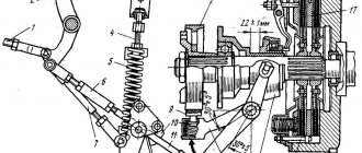
Device PD-8: 1 - gear; 2 - screw; 3 - nut; 4 — regulator lever; 5 - magneto; 6 — crankshaft gear; 7 - coupling; 8 - traction; 9 - finger; 10 - electric starter; 11 - gasket; 12 — exhaust pipe; 13 - cylinder; 14 — exhaust pipe; 15 — piston pin; 16 - piston ring; 17 - piston; 18 — cylinder head; 19 — casing; 20 - high-voltage wire; 21 — spark plug; 22 — muffler; 23 — inlet pipe; 24 - carburetor; 25 — drowning button; 26 — air cleaner; 27 - cover; 28 — throttle lever; 29 — starting device; 30 — connecting rod; 31 - ratchet; 32 - flywheel; 33 — casing; 34 — fan rotor; 35 - crankshaft; 36 - crankcase.
Adjusting the crankshaft speed of the starting engine
A small-sized centrifugal ball regulator is designed to limit the maximum crankshaft speed. The crankshaft speed is adjusted only after repairing the unit, or when replacing the carburetor or regulator, if the factory settings are violated. This work must be performed by a qualified specialist.
Before adjusting the crankshaft speed, it is necessary to set a certain length of rods with the engine not running. The sequence for adjusting the rods is as follows:
1. connect the assembled rod to the throttle lever using a coupling;
2. Pull the rod to the left as far as it will go, while setting the throttle lever to a position in which the throttle is fully open.
The minimum crankshaft rotation speed at idle is adjusted with the engine warm and running. Using the carburetor idle screw, the quality of the working mixture is adjusted, maintaining stable idle speed. To do this, do the following:
1. Turn out the stop screw so that you can completely close the throttle valve;
2. fully open the air damper by moving the rod towards you;
3. Set the throttle valve to achieve minimum rotation speed;
4. Turn out the idle screw completely, and then, slowly unscrewing it, determine the position in which the starting unit will operate stably at minimum crankshaft speed.
Having completed the adjustment, tighten the screw until the throttle lever stops until the position at which the starter of the T-40 tractor will operate stably at minimum speed. The minimum stable rotation speed should be no more than 1200 rpm. Next, the maximum rotation speed is adjusted with pre-heating of the starter using a special regulator screw. When the adjusting screw is unscrewed and the spring is loosened, the maximum idle speed decreases, and when the screw is screwed in and the spring is tightened, it increases.
It is prohibited to adjust the crankshaft speed of the T-40 starting engine by tightening the hinges or changing the length of the rods.
PD-8 gearbox design
With a gradual increase in the free play of the clutch lever of the T-40 launcher, its performance deteriorates. This signals the need to adjust the clutch drive by tensioning the cable braid. The adjusting screw is factory installed so that the gap between the stop of the adjusting screw and the end of the rod is within 0.2-2mm. This size does not change during operation. When adjusting, the clutch lever must be set to its lowest position.
Fuel system features
A screw is installed in the cover of the high-pressure fuel pump corrector, which limits the power of the power plant during equipment break-in. The injectors are secured in the head of each cylinder with cap levers.
The electric torch mechanism installed in the D-160 engine deserves attention. The EFU device is a pin spark plug and an electromagnetic valve attached to it. The fuel evaporates directly in the spark plug, after which fuel vapors mix with air and detonation occurs from the glowing spark plug coil. The resulting flame torch simultaneously heats the air entering the cylinders, thereby facilitating engine starting.