The parking brake drive is connected to the brake valve lever due to special levers and rods, which makes it possible, along with stopping the vehicle using the parking brake, to turn on the service brakes of the trailer or semi-trailer.
Among the root causes of design defects are the following:
- Unfavorable effects of oil (“oiling”).
- Deformation due to temperature effects
- Wear of brake pad linings.
- Loosening the bolts that secure the brake shield to the transfer case.
- Wear of the sector or pawl of the lever (these defects interfere with the possibility of normal fixation of the lever).
Parking brake system URAL-4320
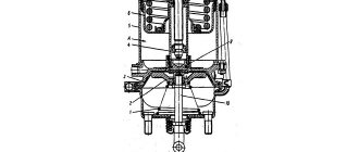
The URAL-4320 parking brake system consists of one drum brake mechanism and a mechanical drive (Fig. 170).
Rice. 170. Parking brake system of the URAL-4320 car : 1 - brake valve lever; 2 — brake valve drive rod; 3 — parking brake lever; 4 - sector; 5, 6 — drive rods; 7 — expansion fist; 8 — brake pad; 9 — adjustment lever; 10 - coupling bolt.
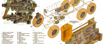
The brake mechanism is located on the transfer case and includes a brake drum, two pads 8 made of aluminum alloy with friction linings, a pad axis, an expansion cam 7 with a lever 9, two tension springs, and a protective disc. The brake drum is mounted on the flange of the rear bogie drive shaft, so the parking brake only brakes the wheels of the rear and intermediate axles. The brake drive consists of a lever 3 with a toothed sector and a latch, two intermediate levers with a roller and a bracket, a double-arm lever, front, middle and vertical rods. The drive has a rod 2 for manual drive of the brake valve.
The brake is adjusted by changing the length of the middle link 5. If the linings are worn heavily, the adjustment is made by moving the lever 9 relative to the expansion cam shaft by one or two teeth clockwise. The correctness of the adjustment is checked by the size of the gap between the pads and the drum, which should be 0.3...0.6 mm. The gap is checked with a feeler gauge through the slot in the protective shield. For a correctly adjusted brake, the latch pawl is installed on the third to fifth tooth of the sector.
Source
Assembly
If you are going to assemble the parking brake, all the above steps must be performed in reverse. Also take into account a few nuances:
- Installation involves pre-lubricating the oil trap gasket.
- The release cam and bushing, the shoe axle and brake pads in the axle support area, as well as the drive axles and bushings must be lubricated with graphite lubricant.
- Tension springs with a radius of 14 millimeters are mounted at the release fist, and with a radius of 10 - at the axis of the block support.
- The designations “a” on the splined ends of the release knuckle and the adjustment lever must be aligned.
- The lever structure on the processing side is mounted to the right inner wall of the bracket structure.
- After assembling the parking brake, make adjustments by placing the lever in the lowest position until it stops.
- The joint between the bracket and the lever should have a “gap” of two millimeters.
- It is important to adjust the space between the brake pads and the drum structure by changing the traction; the gap should be in the range from 3 to 6 tenths of a millimeter.
- The stroke of the lever during braking should be equal to four, five or six sector teeth, and the drive lever should be fixed.
Hand brake device Ural 4320
Emergency braking system for cars Ural-4320-31, Ural-4320-10
The functions of the emergency brake system are performed by one of the circuits of the service brake system. If one of the circuits fails, the emergency brake system provides braking of the vehicle with sufficient efficiency.
Parking brake system for Ural-4320-10, Ural-4320-31 vehicles
The system is designed to ensure vehicle immobility on slopes. The parking brake drive is mechanical. Control is carried out by a lever located to the right of the driver's seat.
Drum-type parking brake with two shoes, self-reinforcing.
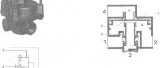
When braking, the force is transmitted from the adjusting lever 11 (Fig. 83) through the lever 10, the link 12 to the release lever 13.
When the brake drum rotates clockwise, the drive force is transmitted from lever 13 through rod 1 to the right shoe 2. The shoe moves away from the support pin and is pressed against the brake drum. In this case, the block, due to friction, is captured by the drum, shifted in the direction of rotation and, through the adjusting device 3, presses the left block 14 against the support pin and the drum.
1-bar; 2.14 pads (right and left); 3 — adjusting device; 4-plug;
5 - asterisk; 6 - shaft; 7 — shield; 8 — lock nut; 9 — eccentric finger; 10 — lever; 11 — adjustment lever; 12 — earring; 13 — expansion lever
When the brake drum rotates counterclockwise, lever 13, resting on rod 1, transmits the driving force to the left shoe 14. The shoe moves away from the support pin and is pressed against the brake drum. Due to friction, the block is captured by the drum, shifted in the direction of rotation and, through an adjusting device, presses the right block 2 against the support pin and the drum.
As the linings wear, the stroke of lever 1 (Fig. 84) increases and the effectiveness of the brake may decrease. If lever 1 is installed on the twelfth tooth of the sector, it is necessary to adjust the gaps between the linings and the drum using an eccentric and an asterisk. To adjust the brake you need to:
1. Lower lever 1 in the cab down until it stops.
2. Disconnect rod 4 from lever 8 on the transfer case.
Do not adjust the gaps between the linings and the drum by changing the length of rod 4, because This causes the parking brake to fail.
3. Adjust the gap between the right block and the drum by loosening the lock nut 8 (see Fig. 83) on the eccentric pin 9 from the shield side by half a turn and, turning the pin clockwise with a wrench, set the gap to 0.3-0 .5 mm. Check the gap with a feeler gauge through the slot in the brake reflector. Tighten the lock nut, preventing the pin from turning.
4. Adjust the gap between the left shoe and the drum. To do this, remove plug 4. Through the hole in the brake shield, turning sprocket 5 from top to bottom with a screwdriver, set the gap to 0.3-0.5 mm. Install the plug.
5. Select the free play of lever 8 (see Fig. 84) on the transfer case, rotating counterclockwise until the force increases noticeably, and check that the hole in the thrust fork 4 matches the hole in the lever 8. If necessary, rotate the thrust fork 4 to align the holes. Install the pin and secure it with a cotter pin.
When the force on the lever in the cabin is 350-400 N (35-40 kgf), the lever pawl 1 should be installed on the 4-8 tooth of sector 3. When the pawl passes the 2-4 tooth of the sector, the parking brake indicator lamp on the instrument panel should light up. The switching moment is controlled by changing the number of spacers 7 under switch 6 of the alarm.
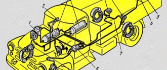
Rice. 84. Parking brake drive: 1-parking brake lever; 2-dog; 3-sector; 4.9-traction drive; 5-link to the trailer brake control valve; 6 — parking brake warning switch; 7-adjusting gaskets; 8-lever; 10-lever adjustment
Source
Dismantling and disassembling parking brake drive parts
- Unscrew and remove the pin that secures the connection between the rod and the lever.
- Remove the four cab bolts and then remove the bracket structure.
- Unscrew the lever axle and remove the washer and lever structure.
- Remove the four bolts and dismantle the bracket structure assembled with the lever structure.
- Disassemble the bracket (you will need to turn the mounting lever bolts on the ox and dismantle the lever structure assembled with the pawl, lever and pawl rod).
- Remove the lever key from the shaft.
- Turn the bolts that secure the flange and the bolt that secures the linkage to the ox, and remove the flange.
- Press out the shaft assembly with the key from the lever structure and from the bracket structure through the passage under the flange.
- Remove the lever key from the shaft; if necessary, also turn the two bolts and remove the sector.
- Press the bushing out of the flange and bracket structure.
- Turn the bolt and remove the lever structure and its key from the shaft.
- Remove the shaft assembly from the bracket structure with the lever structure pressed onto the splined shaft tip.
- There is no need to disconnect the splined tip of the shaft from the lever; if necessary, press the bushing out of the bracket structure.
- If the linings are worn out - if less than half a centimeter remains from the surface of the rivet heads - replace them with new ones.
- If the working surface of the brake drum and shoe assembly with linings is heavily worn (pay attention to the ring grooves), grind them to standard dimensions.
- When turning the block using special equipment, do not forget about the base. An important point: between the release fist and the block crackers you need to place plates, the thickness of which should be one millimeter.
- Oil-coated shoe linings must be treated using unleaded gasoline and then dried. It is advisable to replace those linings that have “looseness” on the surface and traces of delamination due to thermal effects.
- Cracks and other defects of the pads are unacceptable. If the fasteners are loose, be sure to tighten the screws.
Brake system Ural 4320: device, bleeding, diagram
One of the most important systems of a car is the braking system, the main function of which is to control the speed of the car, stop it and keep it in a certain position through the force that arises between the wheels of the car and the road during a stop.
Thanks to the braking system, a change in the speed of the vehicle is ensured, which occurs according to a signal from the owner of the car or electrical systems. The second function of the braking system is to ensure that the vehicle remains stationary after it has stopped. The braking force is generated with the participation of the engine, wheel braking mechanism, electronic or hydraulic retarding brake, which is located in the transmission. To ensure the fulfillment of all designated functions, 3 types of brake systems are installed on URAL-4320 vehicles. What should be the design of the URAL-4320 brake system?
- Service braking system - used at absolutely all speeds of a vehicle of this model to stop or only reduce speed. It starts working almost the moment you press the brake. This type of braking system is the most effective of all.
- Parking brake system - holds the car in place for some time. Allows you to eliminate the possibility of driving a car without a driver.
- An auxiliary braking system is used on vehicles that have a significant weight to ensure they stop on various slopes. Often the operation of this system is provided by a car engine.
The design of the brake mechanism of the Ural 4320 and 5557 car
The working brake system of the Urals of the designated brands is designed to ensure gradual braking of the vehicle partially or to a complete stop, without depending on its speed before braking, terrain features (descent or ascent), specifics of the road surface and other factors.
Brake system Ural
The brake system of the Ural vehicle, assembly models 4320 and 5557, has a mixed type drive (pneumohydraulics), consisting of two circuits. At the same time, it is responsible for braking all six wheels, including the trailer, with the front and rear braking separately (on the axles).
The braking process is started by the brake pedal from the driver's cabin, which is connected by rods and levers to a brake valve, consisting of two sections.
Service brake device:
- A wheel cylinder consisting of two parts located in one housing.
- Brake shield.
- An eccentric for adjustment, which is carried out by turning the bolt using a key.
- Brake pads installed on supporting axles.
- Friction lining.
- Connecting elements - hoses, washers, holders, valves and others.
Service brake device Ural 4320
Brake adjustment process
The service brake adjustment algorithm includes the following sequence of actions:
Adjusting the service brake Ural 4320
- Using a wrench, turn the eccentrics of both brake pads until they stop.
- The left eccentric must be rotated against the clock hand, and the right one - along the clock.
- Loosen the eccentrics by turning them in the opposite direction by half the head of the axle bolt, which is comparable to turning the key 30 degrees.
- Carry out the above steps for all wheels.
- Check the correctness of the adjustment by assessing whether the brake drums heat up while the Urals are moving.
When adjusting the brakes, it is important to be careful not to change the factory location of their support axles in the brake pads. It is necessary to adjust the gaps only in parallel with changing the friction linings or the pads themselves. This is done by turning the support axes and inserting a special probe, the length of which is 200 mm, and the thickness depends on the position of the edge of the overlay and can have values of 0.2 and 0.35 mm. Oily linings must be thoroughly washed with gasoline.
Pneumohydraulic drive device
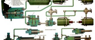
The Ural truck uses a mixed type drive, combining the functions of pneumatics and hydraulics - pneumohydraulic, which consists of two working circuits for the front and rear wheels, plus a third circuit responsible for connecting the trailer brakes (single-wire or double-wire drive).
Hydropneumatic brake drive
The two main circuits of the Ural braking system have the following components:
- Different air cylinders located parallel to each other.
- A brake valve, the upper section of which belongs to the first circuit, and the lower section to the second.
- Cylinder wheels and general brake booster (pneumatic).
- The second circuit additionally includes a brake force regulator.
Pneumatic brake booster for Ural car
Composition of the third circuit:
- Separate air tank.
- Special valves designed to control trailer brakes (separately for single and dual wire actuators).
- Connection heads for each type of drive.
The pneumohydraulic drive of the Urals operates according to the following scheme:
Components of the brake system Ural 4320
- The compressor, through a pressure regulator, directs compressed air to the safety valves (single and triple).
- The valves distribute the resulting air between all cylinders in each independent circuit.
All circuits are additionally equipped with control outlet valves designed to measure air pressure by connecting a pressure gauge to them. The electrical signal sensor is driven (and some other devices) by air from the main air cylinders, from which the intake is carried out through a triple protection valve.
How to bleed and adjust
To make the adjustment you must:
- Turn the eccentrics all the way, with the right part rotating clockwise and the left part counterclockwise. Adjustment of the gap using the pad axis is carried out only in case of wear of the braking surface.
- Loosen the position of the regulators by 30°.
- Check the temperature of the drums while moving. If overheating or insufficient deceleration occurs, readjust the components.
Before bleeding the brake lines, it is necessary to bring the air pressure in the receivers to normal. The surfaces of the cylinders and tanks should be thoroughly wiped from dirt.
To remove air locks from the main and wheel cylinders you need:
- Remove the protective cover installed on the bypass valve fitting. After this, the hose included in the factory tool kit is put on the tube.
- Prepare a clean glass or plastic container that can hold at least 0.3 liters of liquid. Fill the container 1/2 full with brake fluid and lower the free end of the hose into it.
- Unscrew the valve fitting 0.5-0.75 turns, then vigorously press the brake pedal several times, releasing smoothly.
- Manipulations continue until the release of gas bubbles from the tube stops. At the same time, clean liquid is added to the supply tank.
- Depress the brake pedal one last time and hold it in this position. Screw in the fitting and replace the cap.
- By analogy, bleed the wheel cylinders according to the scheme - middle (left), then rear left and right. Then the right middle wheel assembly, right and left front wheels are pumped.
- After removing air from all lines, adjust the fluid level in the supply tank and close the lid.
If fluid replacement is required, the cylinders are disassembled. A lubricant is applied to the working mirror to prevent corrosion.
URAL 5557 30 (31) — Parking brake
| 1 | 4320-1602119 Spring | 1 | 42,00 |
| 2 | 375-3508022 Sleeve | 1 | 20,00 |
| 3 | 4320-3507135 Adjusting lever assembly | 1 | 450,00 |
| 4 | 4320-3507167 Kernel | 1 | call to order |
| 5 | 250515-P29 Nut M12x1.25-6N | 1 | call to order |
| 6 | 252137-P2 Washer 12.OT | 1 | 2,5 |
| 7 | 4320-3507172 Eccentric | 1 | call to order |
| 8 | 252006-P29 Washer 10 | 2 | 6,00 |
| 9 | 4320-3507161 Rod axis | 1 | call to order |
| 10 | 4320-3507162 Barbell | 1 | call to order |
| 11 | 5323-3507047 Coupling spring | 1 | 44,00 |
| 12 | 4320-3507047 Spring | 1 | 43,00 |
| 13 | 252136-P2 Washer 10.OT | 2 | call to order |
| 14 | 250512-P29 Nut M10-6H | 2 | call to order |
| 15 | 252020-P29 Washer 22 | 1 | call to order |
| 16 | 14-0283 Bracket | 1 | 19,00 |
| 17 | 4320-3507168 Upper cup | 2 | call to order |
| 18 | 4320-3507166 Spring | 1 | call to order |
| 19 | 4320-3507156-10 Frame | 1 | call to order |
| 20 | 4320-3507164-10 Star | 1 | call to order |
| 21 | 4320-3507163-10 Screw | 1 | call to order |
| 22 | 260087-P52 Finger 12x35 | 1 | call to order |
| 23 | 258039-P29 Cotter pin 3.2x20 | 2 | call to order |
| 24 | 4320-3507015-01 Brake pad assembly | 1 | call to order |
| 25 | 375-3507020-02 Friction lining | 1 | 104,00 |
| 26 | 255923 Rivet 5x12 | 1 | 2,00 |
| 27 | 4320-3507019-01 Block | 1 | call to order |
| 28 | 260054-P52 Finger 10x20 | 1 | 18,00 |
| 29 | 4320-3507140 Roller with lever | 1 | 695,00 |
| 30 | 4320-3507159 Expansion lever | 1 | 190,00 |
| 31 | 4320-3507165 Earring | 1 | call to order |
| 32 | 4320-3507160 Axis | 1 | call to order |
| 33 | 375-3507126-10 Sleeve | 1 | call |
| 34 | 4320-3507005-01 Brake shield with axle assembly | 1 | call to order |
| 35 | 4320-3507174 Stub | 1 | 15,00 |
| 36 | 200263-P29 Bolt M8-6gх35 | 1 | call to order |
| 37 | 252135-P2 Washer 8T | 1 | call to order |
tprostor.ru
Peculiarities
The Ural brake system is equipped with drum mechanisms that are completely interchangeable. The pneumatic structure itself forms separate brake compartments for different parts of the machine (trailer, front, rear axle). If there is a malfunction in one segment, the remaining analogues in operation are responsible for braking.
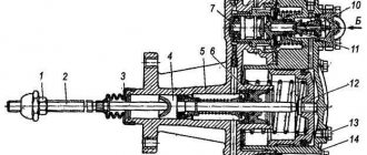
Below is a diagram of the master cylinder with explanations.
- Front pneumatic cylinder.
- Spacer element.
- Radial socket.
- Rear pneumatic cylinder.
- Stock.
- Compression screw.
- Nuts.
- Indicator.
- Main cylinder.
- Cork.
- Brake fluid reservoir.
URAL 4320 40 (41) — Parking brake
| 1 | 4320-1602119 Spring | 1 | 42,00 |
| 2 | 375-3508022 Sleeve | 1 | 20,00 |
| 3 | 4320-3507135 Adjusting lever assembly | 1 | 450,00 |
| 4 | 4320-3507167 Kernel | 1 | call to order |
| 5 | 250515-P29 Nut M12x1.25-6N | 1 | call to order |
| 6 | 252137-P2 Washer 12.OT | 1 | 2,5 |
| 7 | 4320-3507005-01 Brake shield with axle assembly | 1 | call to order |
| 8 | 4320-3507160 Axis | 1 | call to order |
| 9 | 4320-3507172 Eccentric | 1 | call to order |
| 10 | 252006-P29 Washer 10 | 2 | 6,00 |
| 11 | 4320-3507161 Rod axis | 1 | call to order |
| 12 | 4320-3507162 Barbell | 1 | call to order |
| 13 | 258039-P29 Cotter pin 3.2x20 | 1 | call to order |
| 14 | 5323-3507047 Coupling spring | 2 | 44,00 |
| 15 | 252136-P2 Washer 10.OT | 2 | call to order |
| 16 | 250512-P29 Nut M10-6H | 2 | call to order |
| 17 | 252020-P29 Washer 22 | 1 | call to order |
| 18 | 14-0283 Bracket | 1 | 19,00 |
| 19 | 4320-3507168 Upper cup | 2 | call to order |
| 20 | 4320-3507166 Spring | 1 | call to order |
| 21 | 4320-3507047 Spring | 1 | 43,00 |
| 22 | 4320-3507156-10 Frame | 1 | call to order |
| 23 | 4320-3507164-10 Star | 1 | call to order |
| 24 | 4320-3507163-10 Screw | 1 | call to order |
| 25 | 260087-P52 Finger 12x35 | 1 | call to order |
| 26 | 4320-3507015-01 Brake pad assembly | 1 | call to order |
| 27 | 4320-3507019-01 Block | 1 | call to order |
| 28 | 375-3507020-02 Friction lining | 1 | 104,00 |
| 29 | 255923 Rivet 5x12 | 1 | 2,00 |
| 30 | 260054-P52 Finger 10x20 | 1 | 18,00 |
| 31 | 4320-3507165 Earring | 1 | call to order |
| 32 | 4320-3507140 Roller with lever | 1 | 695,00 |
| 33 | 4320-3507159 Expansion lever | 1 | 190,00 |
| 34 | 375-3507126-10 Sleeve | 1 | call |
| 35 | 4320-3507174 Stub | 1 | 15,00 |
| 36 | 252135-P2 Washer 8T | 1 | call to order |
| 37 | 200263-P29 Bolt M8-6gх35 | 1 | call to order |
tprostor.ru
Ural hand brake
The parking brake mechanism of the Urals (handbrake) is designed for braking the Urals during parking and on slopes (during movement it is used only in emergency cases). The handbrake drive is mechanical, and the lever is located on the side of the driver's seat under the right hand.
The handbrake lever is also connected to the trailer braking lever - when it is raised to the top position, the trailer brakes are also activated.
Parking brake mechanism of the Urals
The operating principle of the Ural manual brake mechanism is as follows:
- When the lever is raised, the force from it, bypassing the intermediate one, is transferred to the release lever.
- From the lever through the rod, the impulse passes to one of the blocks - if the drum rotates counterclockwise, then to the left, while along the way, to the right.
- The block is disconnected from the support pin, pressed against the drum, rotated in the direction of rotation and presses the second block.
Adjusting the brake pad clearance of the Ural-4320 car
Adjusting the handbrake: setting the handbrake correctly
One of the elements of the braking system is the hand (parking) brake or, as motorists call it, the handbrake. It is this element that keeps the car stationary when necessary.
The car owner does not know exactly when he may need to adjust the handbrake (and many do not use it at all). But you should not neglect this element of the brake system, since road safety may depend on it (by the way, you will not be able to pass inspection with a faulty handbrake).
Moreover, the process of adjusting the handbrake is one of the simplest processes of self-repairing a car. To implement it, it is enough to have basic knowledge about the structure of the car.
Why do we need a working handbrake?
A hand brake is an element of the vehicle’s braking system, which performs the function of blocking the wheels relative to the axis of movement of the vehicle, and thus ensures the stability of the vehicle on the moving surface (including on a sloped surface).
A working handbrake performs the following functions:
1. Provides vehicle stability on the road surface when parked or on slopes.
2. Helps with emergency braking.
3. If you have the skills, you can use it to enter a controlled drift.
4. If the foot brake breaks down, it can perform its functions.
But it is worth noting that it is impossible to use the handbrake as a permanent braking element (instead of a foot brake), because its main purpose is to secure the car while parking. If you need to use the handbrake when braking while driving, it is not recommended to pull it sharply, as this will cause the car to skid.
The design and principle of operation of the hand brake are quite simple. It consists of three main components:
1. Mechanical drive.
2. Actuator.
3. Control node.
The mechanical drive is made in the form of a hand brake cable. This cable acts on the rear brake pads or on the transmission (depending on the design features of the car). The rocker arm installed in the handbrake ensures uniform cable tension on the two brake pads.
The actuator of the handbrake is the brake pads of the rear axle, which can be driven not only from the handbrake lever, but also from the foot brake pedal. This was done for simplicity of design and for easier vehicle maintenance.
The handbrake is activated by a control unit, represented by a handbrake lever with a ratchet, which controls the tension of the cable. It is located between the driver's seat and the passenger's seat in the central tunnel. On cars with an automatic transmission, there is a foot pedal for the parking brake instead of a lever.
The activation of the handbrake is indicated by a sensor in the form of a light bulb on the dashboard. This sensor helps the driver navigate when the handbrake is on and remember to remove the car from the handbrake before starting to drive. In some cars, if you drive with the handbrake on, a beep will sound, which is very convenient, because drivers often forget to turn off the handbrake.
When do you need to adjust the handbrake?
Diagnosis of the handbrake should be carried out approximately once a month or every 30 thousand kilometers. If you suspect a breakdown, you can diagnose the handbrake more often, especially since it is very simple to perform.
Let's look at two ways to independently diagnose the performance of a handbrake.
1. First method. Drive up a steep slope and tighten the lever. If the car stays on this slope, then the handbrake is fine. If the experiment ends in failure and the car does not stop, then you need to fully pull the handbrake and see if the movement continues. Has the movement continued? This is a clear sign that your handbrake needs repair or adjustment.
2. Second method. Pull the handbrake all the way, engage first gear, and release the clutch pedal smoothly. If the handbrake is working properly, the engine will stall. If the handbrake is faulty, the car will begin to move slowly. This is a clear sign that the handbrake needs to be adjusted or repaired.
The reasons for a handbrake malfunction may be the following:
1. Severe loosening of the brake cable tension.
2. Worn brake linings.
3. Increasing the gap between brake drums and pads.
When do you need to adjust the handbrake?
Adjusting the hand brake is necessary in the following cases:
1. The brake pads were replaced.
2. The brake drums (brake discs) were replaced.
3. The position of the brake pads has been adjusted.
4. The brake body in the handbrake was replaced.
5. The adjusting device was reinstalled.
6. The stroke of the brake lever has increased greatly (up to 10 teeth).
To fix problems with the handbrake, you can either immediately contact a car service station or try to fix the problem yourself. It is not difficult to adjust the handbrake yourself and anyone who has a basic understanding of the structure of the car can handle this operation.
But the adjustment of the handbrake must be carried out in a place specially designated for repairs and in compliance with all rules of personal safety. Before carrying out repairs, you should definitely clarify what kind of handbrake design is installed in the car by looking at the vehicle’s operating instructions.
Pull the handbrake - your actions
Handbrake repair usually comes down to replacing the cable. But in most cases, to resume operation of the handbrake, it is enough to simply tighten it. And this is within the power of every driver.
If the handbrake is adjusted correctly, the number of clicks when tightening the lever should be 5-6. If the number of clicks is less or more, then an adjustment procedure needs to be carried out.
Adjusting the parking brake, regardless of its design features, is based on the principle of adjusting the gap between the brake pads (linings) and brake drums (discs). This gap is adjusted by changing the length of the handbrake cable (its tension), which is located under the interior panel at the bottom of the brake lever.
It is advisable to adjust the handbrake tension in an inspection hole, on a lift or on an overpass. As a last resort, you can use a jack and install support trestles under the rear of the car. There are car models in which the handbrake tension is adjusted directly in the car dealership (you can find out more about this in the operating instructions). In this case, you won’t have to bother with lifting the car.
Tensioning the handbrake consists of the following steps:
1. Raise the car and place it on a support (to have access to the bottom of the car).
2. Raise the handbrake lever 1-3 clicks.
3. Find and loosen the locknut from the adjusting device through the hole in the brake drum.
4. Tighten the adjusting nut and check the tension of the brake cable.
5. If the cable tension has not been achieved, then professional repair of the handbrake is necessary with replacement of its cable. To do this, it is better to contact specialists.
6. If the tension was successful, you need to check the operation of the handbrake by pulling the lever towards you. After this, try to rotate the rear wheel by hand. It should not rotate without effort. After this, you need to tighten the locknut, release the handbrake lever and carry out another similar test. In this case, the wheel should spin freely.
7. Lower the car to the ground and test the operation of the handbrake under real driving conditions. If something goes wrong and there is a suspicion that the problem has not been corrected, you should go through the described steps again or contact a repairman at a car service center.
Subscribe to our feeds on Facebook, Vkontakte and Instagram: all the most interesting automotive events in one place.
Was this article helpful?Yes No
auto.today
basic information
The braking system provides a change in vehicle speeds, which occurs upon a signal from the vehicle owner or the electrical control. The second purpose is to keep the vehicle stationary in relation to the road surface when stopped. The braking force is generated by the machine engine, the vehicle wheel braking mechanism, and the electronic or hydraulic retarding brake located in the transmission. To ensure the functioning of all the previously listed functions, three types of brake systems are installed on Ural 4320 cars. Consequently, the question arises, what kind of braking systems are installed on URAL 4320 cars?
- Working brake system. This system is used at all speeds of the Ural 4320 vehicle without exception to completely stop or reduce speed. Moreover, it starts working almost simultaneously with pressing the brake. This type is almost the most effective in comparison with others.
- Parking brake system. Necessary to keep the vehicle in place for a certain period of time. It is thanks to it that the possibility of moving the car without the command of the car owner is excluded.
- Auxiliary braking system. The auxiliary type is used on heavy vehicles to stop on various slopes. Very often it happens that the functioning of this system is ensured by a machine engine, on which the pipeline is closed using a valve.
The cars are also equipped with an emergency brake release system for parking brakes, a trailer brake drive, an alarm about the functioning of the braking system and a control system. A spare brake system can also be installed, which is used when the main unit is faulty. This type of braking unit can be of 2 types, autonomous or partially functioning thanks to a working system.
The brake system of the Ural 4320 car is equipped with the following mechanisms and devices:
- Brake mechanism;
- Brake valve;
- Pneumatic cylinders;
- Automatic braking force regulator;
- Receivers;
- Pressure gauge;
- Sensors;
- Valves;
- Compressor;
- Adjustment lever;
- Moisture distributor;
- Pressure regulator;
- Pneumatic line;
- Trailer crane;
- Four-circuit safety valve;
- Mechanism of the auxiliary braking system.
Operating principle of the braking mechanism
Let's look at the principle of operation of the braking system of the Ural 4320. When you press the brake pedal, the load will transfer to the amplifier, which creates additional resistance on the master cylinder. The piston of such a cylinder drives away all the liquid in the cylinders of the machine wheels using pipelines. Moreover, simultaneously with this process, the pressure of the drive fluid increases. With the help of pistons in the cylinders of machine wheels, the brake pads move to the discs, or drums.
After pressing the brake pedal, the fluid pressure increases, which means that the stopping mechanisms are activated, which slow down the rotation of the machine wheels and generate braking forces in those places where the machine is in contact with the road surface. Moreover, the more force is applied to the pedal, the more efficiently and quickly the car wheels will stop. The liquid pressure at the moment of stopping can reach from ten to fifteen megapascals.
At the end of the stop, the pedal moves to the reverse position under the influence of the return spring. The piston of the main cylinder also moves into the reverse position. Parts of the springs are retracted from the drums using blocks. Brake fluid passes into the main cylinder from the car wheel cylinders thanks to pipelines. Thus, the pressure of the Ural 4320 braking system decreases. The effectiveness of the braking system is greatly increased thanks to the use of vehicle safety devices.
Auxiliary brake
The Ural's auxiliary braking system is designed for use on long descents. The control button is located on the cabin floor. When you click on it, the following happens:
The auxiliary brake mechanism of the Ural car
- Compressed air enters the pneumatic cylinders, which acts on the pistons and moves them.
- The pistons close the valves - back pressure is created in the exhaust gas pipelines and braking occurs.
- At the same moment, an impulse is applied to the trailer brakes.
Adjusting the pneumatic-hydraulic drive
Drive diagram of the Ural service brakes
The Ural pneumohydraulic drive does not require adjustment and does not require maintenance.
The tightness of a separate pneumatic system is checked by a sharp decrease in pressure on a pressure gauge with two arrows (not lower than 700 kPa), which is located among the driver’s control instruments in the cabin. After stopping the engine (the brake pedal is not pressed), the pressure gauge needles should not twitch much or move noticeably. The same should be observed when the brake pedal is pressed for 20 seconds. At the same time, the tightness of the hydraulic part is assessed.
The functionality of the entire drive is checked by assessing the pressure (650–800 kPa) in all three circuits on pressure gauges connected to the control valves.
Recommendations
The third circuit has a separate air tank and special valves to control the operation of the trailer wheels. It also includes connection heads that differ in configuration, depending on the drive they are intended for. The third circuit is responsible for stopping the trailer.
The compressor operates in cooperation with the regulator, which sends air flow to safety valves, which distribute the resulting mixture between all tanks in each circuit compartment. All chambers are equipped with pressure gauges that allow you to control the pressure indicator.
Source