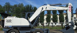
The single-bucket semi-rotary universal excavator EO-2621 is mounted on the chassis of the YuMZ-6L wheeled tractor.
The rotating part and working equipment are controlled using hydraulic cylinders . The following is used as working equipment:
- straight or backhoe
- tap
- grab and forks.
Straight shovel:
- develop soil in small faces
- clean the bottom and walls of the pit
- Load bulk and lump materials.
Backhoe:
- digging trenches for laying cables and storing root crops
- digging small pits.
Crane:
- loading piece materials
- lay pipelines
- uprooting small stumps
- they put up pillars
- medium sized trees are planted
- perform installation work when repairing machines.
The bucket is used to load low-density materials, while the forks are used to load garbage, steel shavings and other loads weighing up to 400 kg.
Excavator EO 2621
A strapping frame and a bulldozer equipment frame are attached to the tractor .
A rotating column is installed on the frame, to which the boom is attached. The boom is raised and lowered using a hydraulic cylinder. The handle with the bucket is rotated using hydraulic cylinders. The bucket rotates relative to the lower hinge of the hydraulic cylinder handle.
Rotation of the working equipment is possible by 160°.
The excavator is equipped with a bulldozer blade, which also serves as a counterweight.
To increase stability while digging, the excavator is equipped outriggers . The excavator is controlled from the cabin using hydraulic valves.
To install a backhoe, the bucket is installed with its teeth outward and secured to the lower fork of the handle using additional rods The hydraulic cylinder rods are attached to the lower arm bracket. The bottom of the bucket is pivotally connected to its body and can be opened for unloading using a hydraulic cylinder.
The body of the rotary column with the working equipment is rotated using a chain that goes around the sprocket. The ends of the chain are connected to the rods of two single-acting hydraulic cylinders.
When one of them is turned on, the rod turns the steering column body through a chain in the corresponding direction.
1 — bulldozer blade; 2 — hydraulic cylinder of the bulldozer blade; 3 — bulldozer frame; 4 — fuel tank; 5 - tractor; 6 — hydraulic system tank; 7 - pumping group; 8 — cabin; 9 - frame; 10 — seat; 11 — distributors; 12 — rotation mechanism; 13 — hydraulic cylinder of the handle; 14 — handle; 15 — bucket hydraulic cylinder; 16 - ladle; 17 — boom hydraulic cylinder; 18 - arrow. 19 — connecting pipelines; 20 — rotary column; 21 — hydraulic cylinders; 22 — outrigger.
Main technical characteristics
Chassis based on the YuMZ-6L tractor
| Bucket capacity, m*: | |
| backhoe | 0,25 |
| straight shovel | 0,25 |
| Backhoe digging depth | 3m |
| Maximum unloading height of the backhoe | 3.3m |
| Diesel | D-50P |
| Diesel power, kW | 40 |
| Movement speed | 1.9 – 17.3 km/h |
| Maximum backhoe performance | 60 m3/h |
| Working weight | 5.7 t |
5.
DESCRIPTION OF THE HYDRAULIC SYSTEM OF THE EXCAVATOR EO-2621/EO-2626
The excavator hydraulic system is shown in Fig. 1 and consists of gear pumps N1 type NSh-32 and N2 type NSh-100-3 (see Fig. 3), hydraulic distributor RGS16I19M and R-80, tractor hydraulic system, filter F, type FL. 000, hydraulic cylinders Ts1...Ts12 working bodies, tank B and tractor tank.
The working fluid is supplied from tank B to pump H2, and from the tractor tank to pump H1. Pump H1 supplies the liquid to distributor P1, which is included with the tractor or can be retrofitted. Pump H2 supplies the liquid to the distributor RGS16.6I19M. The drain line of the distributor P2 is connected to the drain filter F.
To control the loader or blade, the tractor distributor P1 is used. Liquid from the distributor is supplied to the piston or rod cavities of the hydraulic cylinder Ts7 and Ts8 or Ts11 and Ts12.
Distributor P1 is made according to the scheme (see Fig. 1), ensuring the floating state of the working parts. This state corresponds to the fourth position of the control handle (see Fig. 1). In this regard, during operation it is necessary to take into account that when the control handle is switched all the way forward, the distributor spools P1 are installed in a position in which the cavities of the hydraulic cylinder will be connected to each other and to the drain. This mode provides slight (due to the pressure in the drain line) pressing of the blade to the surface on which the tractor is located.
To install the outriggers of the excavator, the 1st and 2nd sections of the RGS16.6I19M distributor are used. Raising the outriggers to the transport position and hanging the excavator is carried out by sections 1 and 2 of the RGS16.6I19M hydraulic distributor. To install the support, the distributor handles 1 and 2 are set in the down position until it stops. The distributor has a circuit in which there is no floating position, i.e. There are only three spool positions (see Fig. 1). To keep the excavator in a transport and suspended state for a long time, hydraulic locks of the hydraulic distributor are used.
The 6th section of the RGS16.6I19M2 distributor controls the hydraulic cylinders for turning the excavator. Smooth turning is achieved by regulating the supply of working fluid and the operation of the overflow valve, which provides protection against water hammer, overloads, increased pressure and the occurrence of vacuum in the cavities of the hydraulic cylinders. Control is carried out by handle 6.
The diagram of the rotary column and the placement of hydraulic cylinders on it is shown in Fig. 2
The rotary column is a metal structure that rotates on axes 4 relative to the frame 2 of the excavator. The column is rotated by two hydraulic cylinders 1, fixed in the carriage using axles 3. In the transport position, the column is fixed with a pin 5, in hole C. When the excavator is operating, the pin is removed.
The hydraulic diagram of the column rotation is shown in Fig. 1 Hydraulic cylinders 5 and 6 rotate relative to the axis. When the spool of the distributor section is turned on, the supply of working fluid through pipelines enters the cavity of the upper cylinder and the rod cavity of the lower cylinder, and the rod cavity of the upper cylinder and the cavity of the lower cylinder are connected to the drain (see Fig. 1). The resulting force acting on the pistons of the hydraulic cylinders rotates the rotary column with the working equipment relative to the axis. To stop the rotation of the equipment, the hydraulic valve spool is set to the neutral position, the cavities of the hydraulic cylinders are locked, and the movement of their rods for some time occurs due to the working equipment moving by inertia.
Rice. 2 3 – axle; 4 – axis; 5 – finger; 6 – column
Changing the direction of rotation is carried out by switching the hydraulic valve spool to another operating position, in which the cavities of the discharge cylinders are connected in the opposite direction. Stopping the equipment when it is turned to its extreme position is ensured by brake devices built into the hydraulic cylinder.
The main control of the boom is carried out by section 4 of the P2 distributor. When the distributor spool moves, the working fluid from pump H2 enters the piston or rod cavities of the hydraulic cylinder Ts4. The smooth lowering of the boom and the entire mechanism is ensured by the smooth opening of the distributor spool and the operation of the overflow valve of the distributor section.
The handle is controlled by the 3rd section of the distributor. When the distributor spool is switched, the working fluid from pump H2 enters the corresponding cavities of the hydraulic cylinders C2 and C3, which control the excavator handle. The bucket is controlled by section 5 of the distributor. When the distributor spool moves, the liquid from the pump enters the corresponding cavities of the hydraulic cylinder C1 of the bucket. To protect against overload of the hydraulic cylinder when the corresponding distributor spool is locked, overflow and safety valves are used.
The design of tank B of the working fluid is a container separated by calming partitions. A dipstick is installed on the tank to determine the level of the working fluid, and a filler neck for filling the working fluid.
contents .. 1 2 3 4 ..
Connection diagram for rotary cylinders EO 2621
Hydraulic system of EO-2621A excavators - part 1
Two hydraulic systems operate on the excavator: one of them is installed on the tractor, the other is for driving the working equipment units on the excavator.
The tractor hydraulic system includes gear pump 3 (Fig. 154) of the NSh-67k type, which is driven from the diesel shaft through a gearbox. Pump 3, through the hydraulic distributor 10, supplies fluid to the hydraulic cylinder 7 of the boom and to the hydraulic cylinders 12 and 13 of the turning mechanism, as well as through the tractor hydraulic distributor 17 to the hydraulic cylinders 15 of the outriggers and the hydraulic cylinder 16 of the bulldozer.
The excavator hydraulic system includes two gear pumps 2 and 4 of the NSh-32U type, which supply fluid through hydraulic distributor 5 to hydraulic cylinders 7, 8 and 9. Hydraulic cylinder 7 of the boom is powered either from each hydraulic system separately, or from two hydraulic systems with the total flow of working fluid in order to speed up the working fluid. operations. The working fluid coming from tank 1 to pumps 2 and 4 is pumped into hydraulic valves 5, 10 and 17 and, depending on the position of the control levers, is either sent to the hydraulic cylinders of the mechanisms, or through filter 19 to be drained into tank 1.
To protect the excavator mechanisms from overloads, valves are installed in the hydraulic distributors. An unloading valve 6 is connected to the pipelines of the hydraulic cylinder 7 of the boom to protect against bending of the hydraulic cylinder rod when reactive pressures occur. If the pressure in the locked piston cavity of the hydraulic cylinder 7 increases excessively, the unloading valve 6 bypasses liquid into the rod cavity of the hydraulic cylinder, and the excess liquid into tank 1.
The hydraulic diagram of the mechanism for turning the working equipment together with the rotating column is shown in Fig. 155. In order to increase the torque developed by the turning mechanism, the working fluid is supplied under pressure into the piston cavities of hydraulic cylinders 4 and 5.
The rod cavities of hydraulic cylinders 4 and 5 are also filled with liquid and connected to each other. If liquid is supplied to the piston cavity of one of the hydraulic cylinders, pressure will also arise in its rod cavity, which is transferred to the rod cavity of the other rotation hydraulic cylinder. As a result of this, the rods will begin to move together with the chain 7 of the rotation mechanism. Chain sprocket 8 will begin to rotate together with the rotary column body and the working equipment attached to it. Fluid losses in the rod cavities are compensated through check valve 6 connected to the pipelines of the hydraulic cylinders of the handle.
154 Hydraulic diagram of the EO-2621A excavator with kinematic elements:
1—working fluid tank; gear pumps:
3—НШ-67к tractors; hydraulic valves: 5 and 10 - excavator,
6 — unloading valve of the boom hydraulic cylinder; hydraulic cylinders:
9 - bucket, 12 and 13 - turning mechanism,
11 and 14 - check and bypass valves;
19 - working fluid filter
155 Diagram of the turning mechanism: 1 and 2 - bypass and check valves, 3 - damper devices (throttles) of the turning hydraulic cylinders, 4 and 5 - turning hydraulic cylinders, 6 - check valve for feeding hydraulic cylinders, 7 - purpose of the mechanism, 8 - chain sprocket
3 and 7 - clamping and subtype clips, 4 - plates,
8 and 10 - sealing and support rings,
12 - centering sleeve, 13 and 14 - drive and driven gears,
Smooth automatic braking of the turning mechanism in the middle of the stroke is carried out using the bypass valve 7, and at the end of the stroke - due to damping devices 3 mounted in the rear covers of hydraulic cylinders 4 and 5.
The design of the working fluid tank is described in § 36 (see Fig. 136), and the general design of the pumping unit is described in § 32 (see Fig. 119). The NSh-32U pump is almost identical in design to the NSh-32E pump (see Fig. 101). The NSh-67k pump (Fig. 156) has design features and a volumetric flow increased by 2.1 times compared to the NSh-32U pump.
The pump gears are placed in a bearing race 7, made in the form of a half-cylinder with four bearing seats. Adjustment of the gap between the gears and the housing in the radial direction is carried out by a clamping ring 3, resting on the pins of gears 13 and 14,
The cuff 1 forms a chamber in which the pressure of the liquid presses the holder 3 against the gear teeth. The gap between the housing 16 and the clamping ring 3 is covered by plate 2. The clamp 3, as its supporting surfaces wear, compensates for the radial gap between its sealing surface and the gear teeth. The mechanical seal of the gears is achieved using two plates 4, the pressing force of which is created due to the pressure of the liquid located in the chambers limited by the cuffs 6. To balance the forces transmitted through the plates 4, in the clamping ring 3 there are chambers limited by the cuffs 5, which also receive liquid under pressure.
The flow of liquid along the pump shaft is prevented by cuffs 9, which are protected from mechanical damage by support 10 and retaining rings 11. The centering sleeve 12 prevents rotation of the gear 13 assembled with the races and plates during pump operation. The cover 15 is attached to the pump housing 16 with bolts 17. The seal between the housing and the pump cover is achieved using a rubber ring 8.
From the pump to the hydraulic cylinders of the bulldozer and outriggers, the working fluid is supplied through the tractor hydraulic distributor, and to other hydraulic cylinders through three-spool hydraulic distributors (Fig. 157) with built-in safety and bypass valves.
The housing 14 of the three-spool hydraulic valve contains a bypass valve (which includes a plunger 13, a damper 11 and a spring 10), as well as a safety valve consisting of a housing 9, a seat 8, a ball 7, a guide rod b, a spring 5, an adjusting screw 2, a lock nut 4 and cap 3. In addition, it has many different cavities connected to each other by channels. In combination with spools 15 and a bypass valve, these cavities and channels make it possible to direct the flow of working fluid from the pump to the hydraulic cylinders of the working equipment, and then return it back to the tank.
The spools 15 are set to the neutral and working positions by the control levers; they return to the neutral position under the action of springs 16.
157 Hydraulic distributor of the EO-2621A excavator: a - structural diagram, b - section of the body along two spools;
5 and 10 - springs of safety and bypass valves,
Source
Loaders-excavators PE-F-1B-1, PE-F-1BM-1
Warning!
Recently, information resources are increasingly appearing on the Internet, the names of which are consonant with the names of the domain name, the labeling of manufactured products, as well as the name, formerly “PO Yurmash”, “TD “Yurmash”, “Yurmash-crane”.
LLC "Yurginsky Machinery Plant" informs that the sites:
- www.tdyumz.ru - LLC "TD Yurginsky Mechanical Plant"
- www.yurmash.ru - LLC "PO Yurmash"
- www.ysdm.ru – Stroydormash-Service LLC
- www.yurmash.narod.ru - JSC "Yurmash"
- www.yurga-zavod.ru – Yurga Mash Plant
- www.yurmash.su – Carrie LLC
- www.yurmashservis.ru – Yurmash Service LLC
- www.kranzip.ru – REVERS LLC
- www.ks4361.ru – Yurginsky Crane Repair Plant LLC
- www.ooo-trio.ru – Trio LLC
- www.s-kran.ru – KoftunoFF LLC
- www.yurga-zavod-agro.ru – LLC “Yurga Agricultural Equipment Plant”
- www.agrosnab-siberia.ru – Agrosnab-Siberia LLC
are not information resources of Yurginsky Machine-Building Plant LLC, and the enterprises presented on these sites are not partners and have nothing to do with the Yurginsky Machine-Building Plant.
Yurginsky Machinery Plant is not responsible for possible risks associated with the use of any information published on these sites and equipment purchased from these companies.
If applications or commercial offers are sent to you from companies whose names are similar to Yurginsky Machine Plant LLC, please inform us by email
