The engine fuel supply equipment is of a divided type. It consists of a high-pressure fuel pump with an all-mode speed controller and a built-in corrector for adjusting the fuel supply, a fuel priming pump, injectors, coarse and fine fuel filters, low and high pressure fuel lines.
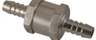
From the tank, through the coarse filter, fuel is sucked in by the fuel priming pump and supplied to the fine filter and then to the high-pressure fuel pump. The fuel pump, in accordance with the operating order of the cylinders, supplies fuel through high-pressure fuel lines to the injectors, which spray it into the engine cylinders. Through the bypass valve in the fuel pump and the jet in the fine filter, excess fuel, and along with it the air that has entered the system, is discharged through the fuel line into the fuel tank. The fuel that has leaked into the cavity of the injector spring is discharged through the drain pipeline into the tank.
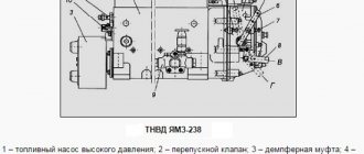
Design of the YaMZ-238 fuel system
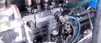
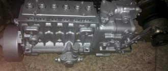
High pressure fuel pump YaMZ 238
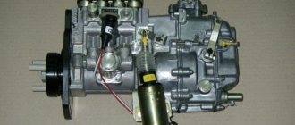
Fuel injection pump of the YaMZ-238 diesel engine of MAZ-5516, MAZ-64229, 6303 and Kraz-255, 6510, Kraz-65101 vehicles, assembled
. The pump is located in the engine camber between the rows of cylinders and has a gear drive. The high-pressure fuel pump is eight-section, according to the number of engine cylinders. Engines are equipped with high-pressure fuel pumps of various models, which have design and adjustment differences.
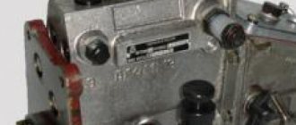
Model 173 High Pressure Fuel Pump
1 – high pressure fuel pump; 2 – bypass valve; 3 – damper coupling; 4 – bolt for limiting the maximum rotation speed; 5 – speed regulator; 6 – regulator control lever; 7 – bolt for limiting the minimum rotation speed; 8 – stop bracket; 9 – fuel priming pump; 10 – starting feed adjustment bolt; 11 – boost fuel supply corrector. A – lever position at minimum idle speed; B – lever position at maximum idle speed; B – position of the bracket during operation; Г – position of the bracket when the feed is turned off. The speed regulator 5, the fuel priming pump 9 and the damper clutch 3 are combined with the fuel pump in one unit.
Fuel flow analysis
You must be able to correctly assess fuel movement if you plan to set the ignition yourself.
When rotating the shaft:
- the fuel in the compartment moves;
- the strokes on the flywheel case are aligned with the mark. Its value matches the number on the OVT coupling;
- the mark on the shaft pulley coincides with a mark with a similar number on the body of the gears.
If there is no alignment of strokes when starting the movement of the fuel, it is recommended to carry out the following manipulations:
- remove the fixing screws;
- twist the shaft coupling of the YaMZ 238 turbo engine on the edge in the opposite direction of rotation;
- secure all fasteners;
- re-evaluate the injection angle.
If, when starting fuel movement, the strokes have passed the required mark, do the following:
- along the thread of the edge it is necessary to rotate the coupling half of the internal combustion engine shaft;
- move the clutch 1 notch relative to its edge, which equates to 4 strokes on the disc or body of the timing gears.
Advice! As soon as all the manipulations are completed, it is recommended to change the location of the divisions on the coupling half of the YaMZ 238 injection pump drive shaft and its edge.
Fuel injection pump design for diesel engine YaMZ-238
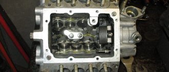
The YaMZ-238 high-pressure fuel pump consists of sections, separate pumping elements located in a common housing.
The number of sections is equal to the number of engine cylinders. Section of the high pressure fuel pump YaMZ-238
1 – pump housing; 2 – lower plate of the pusher; 3 – pusher spring; 4 – upper plate of the pusher; 5 – rotary bushing; 6 – plunger; 7 – plunger bushing; 8 – discharge valve seat; 9 – discharge valve; 10 – valve stop; 11 – fitting; 12 – pressure flange; 13,14 – gaskets; 15 – section body; 16 – rack; 17 – pusher; 18 – pusher roller; 19 – cam shaft. In the pump housing 1 there are housings of sections 15 with plunger pairs, discharge valves and fittings 11, to which high-pressure fuel lines are connected. Discharge valve 9 and valve seat 8, as well as plunger 6 with sleeve 7 are precision pairs that can only be replaced as a set. The plunger sleeve is locked in a certain position by a pin pressed into the section body. The plunger 6 is driven from the cam shaft 19 through the roller tappet 17. The spring 3, through the lower plate 2, constantly presses the tappet roller against the cam. The pushers, which have flats on the side surfaces, are held against rotation by clamps pressed into the pump housing. The design of the plunger pair allows fuel dosing by changing the start and end times of the supply. To change the amount and moment of the start of fuel supply, the plunger in the sleeve is turned by a rotary sleeve 5, which engages with rack 16. The uniformity of fuel supply at maximum mode is adjusted by each pump section by rotating the section body with the section fastening nuts loosened. Changing the geometric start of injection depending on the amount of feed (engine load) is ensured by control edges made at the end of the plunger.
Injection angle calibration
To correctly determine the angle, there are 2 control clearances on the wheel case, and on the disk there are angle reference points at 2 points.
The bottom value is indicated by numbers, and those on the side are indicated by letters.
- A – 20°;
- B – 15°;
- B – 10°;
- G – 5°.
To install the YaMZ 238 ignition, you need to open the openings on the rotary disk case. Next, you should rotate the crankshaft of the internal combustion engine until the strokes on the pulley connect with the body of the timing gears. You can also pay attention to the convergence of the strokes on the flywheel with the reference point.
Reference! During calibration, the obtained indicators must coincide with the regulated ones - VT (6°–7°). And all manipulations are carried out with closed pistons in the first cylinder.
Angle calibration must be carried out until the value “A” coincides with o. The first is at the end, and the second is at the pointer.
Operating principle of the injection pump section of the YaMZ-238 diesel engine
When plunger 6 moves downward under the action of spring 3, fuel under low pressure created by the fuel priming pump enters through a longitudinal channel in the housing into the space above the plunger. As the plunger moves upward, fuel enters the high-pressure fuel line through the discharge valve and is bypassed into the fuel supply channel until the end edge of the plunger closes the inlet hole of the sleeve. With further upward movement of the plunger, the pressure in the space above the plunger increases sharply. When the pressure reaches such a value that it exceeds the force created by the injector spring, the injector needle will rise and the process of injecting fuel into the engine cylinder will begin. With further upward movement of the plunger, the cut-off edges of the plunger open cut-off holes in the bushing, which causes a sharp drop in fuel pressure in the discharge line, the nozzle needle landing on the locking cone of the nozzle and stopping the supply of fuel to the combustion chamber. On the inner surface of the plunger sleeve 7 there is an annular groove, and in the wall there is a hole for draining fuel that has leaked through the gap in the plunger pair. The seal between the plunger bushing and the section body, the section body and the pump body is carried out with rubber rings. From the cavity around the plunger bushing, the leaked fuel flows through the groove on the plunger bushing into the low pressure cavity of the pump housing and then through the bypass valve and pipeline into the fuel tank. At the bottom of the YaMZ-238 injection pump housing there is a cam shaft. The cam shaft rotates in tapered roller bearings and an intermediate support. The cam shaft is installed with an interference of 0.01 - 0.07 mm, which is provided by the adjuster and gaskets installed between the bearing cover and the pump housing. The sections are connected to the pump speed controller through a rail. The rack moves in guide bushings pressed into the pump housing. At the end of the rack protruding from the pump there is a bolt 10, with which it rests against the protective cap when the rack is in position before starting the engine. When the bolt is removed from the rack, the starting feed decreases. Pump lubrication is centralized, from the engine oil system. The oil is supplied to the boost corrector, from where, merging into the cavity of the regulator, it enters the cavity of the pump cam shaft.
A series of steps to adjust the injection angle
To carry out proper calibration of the UOVT, a number of manipulations are performed.
- Evaluate the tightness of the fit of the YaMZ 238 ignition timing clutch, then tighten the screw of the terminal shaft.
- Unscrew the 2 screws of the clamping unit. Oval openings will help with this. On the damper coupling, connect o and “B”.
- Attach the screws to the drive.
- Carry out an analysis in the area where the plates are fixed. The permitted deviation of the plate package from the norm is within ±1 mm.
- Rotate the crankshaft and evaluate whether the OVT is set correctly. The permitted deviation from the norm is within 1° of crankshaft rotation or one division.
- Check the oil level in the OVT clamping unit. You should also check the degree of wear of the YaMZ 238 injection pump oil seal.
- Finally, check how the fuel injection angle is set.
Advice! To ensure that the angle is correct, you need to install the clamping unit with the opening in the upper position and remove the covers. When the unit rotates quietly at 70°, lubricant should flow from the opening. Then screw the lids on.
Speed regulator for diesel fuel injection pump YaMZ-238
The high-pressure fuel injection pump speed regulator is a mechanical all-mode direct action with overdrive transmission to the load drive, designed to maintain the engine speed mode set by the driver by automatically changing the amount of fuel supplied depending on changes in the load on the engine.
Speed regulator of the fuel pump of the YaMZ-238 engine
1 – boost fuel supply corrector; 2 – axis of the double-arm lever; 3 – inspection hatch cover; 4 – regulator spring; 5 – double-arm lever; 6 – rack lever spring; 7 – double-arm lever screw; 8 – buffer spring; 9 – buffer spring housing; 10 – adjusting bolt; 11 – spring lever shaft; 12 – negative corrector; 13 – corrector spring housing; 14 – negative corrector spring; 15 – backstage bracket; 16 – negative corrector bushing; 17 – regulator lever; 18 – negative corrector lever; 19 – power adjustment screw; 20 – rack lever; 21 – backstage; 22 – heel; 23 – cargo coupling; 24 – regulator weights; 25 – load holder; 26 – load axis; 27 – drive gear; 28 – crackers; 29 – load holder roller; 30 – glass; 31 – spring lever 32 – rack rod; 33 – rack; 34 – stop. In addition, the pump governor limits the maximum engine speed and ensures that the engine operates at idle speed. The regulator has a device for turning off the fuel supply at any time, regardless of the engine operating mode. By automatically maintaining the speed mode under changing loads, the regulator ensures economical engine operation.
Engine structure D-240 Lubrication system
005
Engine design D-240
Lubrication system
The lubrication system (Fig. 9) is combined. Depending on the operating conditions of the parts, oil is supplied to their rubbing surfaces (main and connecting rod journals of the crankshaft, camshaft bearing journals, intermediate gear bushings and fuel pump gears) under pressure, but with a pulsating flow (valve mechanism) and splashing (other parts). The main assembly units included in the diesel lubrication system are oil pump 3 with an oil receiver, full-flow centrifugal oil filter 2, oil cooler 1. In addition, the lubrication system includes oil pipelines, connecting fittings, control devices, safety valves, etc. Part of the assembly units diesel engines that are not included in the main lubrication system (water pump, starting motor, fuel pump, starting motor transmission mechanism) have an autonomous lubrication circuit.
Rice. 9. Diagram of the lubrication system;
1 - oil cooler; 2 - oil filter; 3 - oil pump; 4 — oil sump plug; 5 — oil pump receiver; 6 - pressure gauge. 7 - drain valve. 8 - pressure reducing valve; 9 - filter valve. 10 - oil sump
Motor oil is used as the main lubricant for diesel engines: in summer - grade M10G2, in winter - grade M8G2 (GOST 8581-78) with a replacement period after 480 hours of operation. Motor oil is used as a substitute: in summer - grade M10B2, in winter - grade M8B2 (GOST 8581-78) with a replacement period after 240 hours of operation.
The oil pump (Fig. 10) is a single-stage, gear type, installed on the cover of the first main bearing of the crankshaft and driven by the diesel crankshaft. The main parts of the pump: body 2, cover 5, drive gear 6 and drive gear 9, mounted on shaft 8, and driven gear 4, located on pin 3.
Rice. 10. Oil pump:
1 - oil intake; 2 - pump housing; 3 — driven gear pin; 4 — driven gear; 5 — housing cover; 6 — pump drive gear; 7 - pin; 8 — pump shaft; 9 - drive gear; 10-pipe.
When gears 9 and 4 rotate, a vacuum is created in the suction zone, due to which oil flows through the oil intake into the pump. Getting between the gear teeth, the oil is pumped into the line, and from it is supplied to the rubbing parts.
The depth of the borings for the gears in the housing, the width of the gears and their location are carried out with great precision. To seal the internal cavity of the oil pump, the mating planes of the housing and cover are ground. To create bearing alignment, the cover is connected to the housing using two control pins, the holes for which are machined together. Therefore, moving the cover from one pump to another is unacceptable. The pump flow is 36 l/min at a rotation speed of 2320 rpm and the pressure developed by the pump is 0.70…0.75 MPa (7.0…7.5 kgf/cm²).
Fig.5. Diagram of operation of the lubrication system pump:
1-body; 2 and 4 driven and drive gears; 3-oil intake; 5-discharge valve; 6,8 and 9-locking ball; safety valve spring and adjusting screw; 7-hole for oil bypass.
The oil filter (Fig. 11) is designed to clean the oil circulating in the lubrication system. The diesel engine is equipped with a centrifugal filter with a nozzleless hydraulic drive.
Rice. 11. Centrifugal oil filter (centrifuge):
1 - cap; 2 — washer; 3 - cap nut; 4 - nut; 5 - special nut; 6 - ring; 7 - tangential hole; 8 — rotor frame; 9 — oil drain pipe; 10 — nozzles (oil flow swirler); 11 — inner glass; 12 — lower rotor cover; 13 — rotor cover; 14 — rubber sealing ring; 15 — rotor axis; 16 - safety valve; 17 — radiator (reducing) valve; 18 — drain valve; 19-filter housing; 20- rotor glass; 21 — cap gasket.
An axis 15 is screwed into the centrifuge body 19, on which a rotor rotates, consisting of a frame 8, an inner cup II, a bottom cover 12 and a top cover 13. The cover 12 is attached to the frame 8 with a nut and sealed with a rubber ring 14. Washer 2 and nut 4 installed on the upper threaded end of the axis 15, limit the axial movement of the rotor. The rotor is closed on top with a cap /, which is secured with a nut 3 and washer 2. An oil drain pipe runs inside the axle.
From the oil pump, oil flows through a channel in the cylinder block, and then through an annular channel and holes in the rotor axis into the nozzle 10, which is secured to the axis with a pin. Through the slots in the nozzle, the oil is supplied in a tangential direction, acquires a rotational movement and, through holes in the rotor frame, enters the inner cup II. The deflector collar of the rotor cover directs the oil upward. Under the influence of centrifugal forces, products of combustion and decomposition of oil and wear of parts are deposited on the inner walls of the rotor. The purified oil is thrown out at high speed through a tangential hole in the upper part into the internal groove of the rotor housing in the area of the radial inlet holes 7 of the rotor axis. This creates a reactive force that rotates the rotor. Then the oil enters the main oil line through the holes in the rotor axis and tube 9.
Safety valve 16 maintains a pressure in front of the rotor of 0.65…0.70 MPa (6.5…7.0 kgf/cm²). If the oil pressure at the rotor inlet is higher than this, it drains through the valve into the oil pan.
Drain valve 18 is adjusted to a pressure of 0.20…0.30 MPa (2.0…3.0 kgf/cm²) and maintains the required pressure in the main oil line.
Reducing (unregulated) valve 17 serves to bypass cold oil into the main line, bypassing the oil cooler. The valve spring force is less than the radiator resistance to the flow of cold oil, so if it is cold, the valve opens and oil flows into the line.
The oil cooler (see Fig. 9) is designed to cool the oil, the temperature of which can increase significantly during prolonged operation of the diesel engine at full load, especially at high ambient temperatures. Passing through numerous radiator tubes, the oil is cooled by the counter flow of air by 10...15°C and enters the diesel engine.
Purpose of the lubrication system
Reducing the friction force between rubbing parts; Reduced heating of parts; Removing wear and carbon deposits; Corrosion protection; Cooling; Sealing the combustion chamber.
Supply system
The diesel power system (Fig. 15) consists of a fuel tank 2, coarse 3 and fine fuel filters 7, fuel supply pumps and low and high pressure fuel lines, air filter nozzles and air lines.
Rice. 15. Power system diagram:
1 — muffler; 2 — fuel tank; 3 — fuel coarse filter; 4 — booster pump: 5 — fuel pump; 6 - regulator; 7 — fine fuel filter; 8 — air cleaning intake manifold; 10 — electric torch heater; 11 - drain pipeline; 12 — nozzle; 13 - combustion chamber; 14 — exhaust manifold.
The air, thanks to the vacuum created in the diesel cylinders, is sucked in from the atmosphere and enters the air cleaner 8, where it is successively subjected to three-stage cleaning (it was previously indicated how important the quality of air cleaning is for the engine as a whole, and especially for the parts of the cylinder-piston group). Purified air enters the diesel cylinders through the intake manifold 9 and channels in the block head.
Fuel is supplied to the diesel cylinders in precisely measured quantities (depending on the diesel load), at strictly defined times and under high pressure, ensuring its fine atomization in the environment of compressed and heated air. Fuel is poured into the neck of the fuel tank 2, inside of which there is a strainer. From the tank, the fuel flows by gravity through the fuel line to the coarse filter, where it is cleaned of large mechanical impurities. From here, the pre-cleaned fuel enters the booster pump 4, which is mounted on the fuel pump and driven by its cam shaft. A hand pump is installed on the body of the booster pump, with which the system is filled with fuel and air is removed from it before starting. The booster pump pumps fuel into the fine filter 7, where the fuel is freed from small impurities. Then the fuel enters the fuel pump 5, which, under high pressure, pumps it into the injectors 12. At certain points in time, the injector injects fuel into the combustion chamber 13. The fuel that has leaked through the gaps between the needle and the nozzle body is discharged from the injector into the fuel tank through the drain pipeline 11, connecting all four nozzles. Combustion products are removed from the cylinder through the exhaust manifold, passed through the muffler and released into the atmosphere.
Air purifier 8 is an air filter in which the air sucked in by the diesel engine undergoes sequential triple cleaning: dry centrifugal, inertial and oil-contact. Large particles (first stage) of air are removed in an inertial coarse filter installed on the central pipe of the air cleaner. Air is sucked through the mesh and, passing between the swirler blades, acquires a rotational motion. Under the influence of centrifugal forces, dust particles are thrown towards the wall of the hood and removed through the slots in its upper part. The air passes through the second stage of purification when, at the exit from the central pipe, it hits the oil in the cup, abruptly changes direction and loses dust particles captured by the oil. The air undergoes the last, third, stage of purification by passing filter elements made of nylon weave, installed between the support clips in the air cleaner housing. The bottom of the air cleaner housing is covered with a pan, which also serves as an oil reservoir. The pan is attached to the air cleaner body with coupling bolts.
The intake manifold 9 is an air duct consisting of three parts: an air supply pipe, an adapter pipe and the manifold itself, connected with bolts. An emergency diesel stop mechanism is mounted in the transition pipe. The damper of this mechanism is controlled remotely using an external lever, a cable and a return spring. An electric torch heater is installed on the intake manifold, which heats the air entering the cylinders, and thereby significantly facilitates starting the diesel engine in the cold season.
The exhaust manifold 14 is made in the form of a cast iron with three flanged pipes connected to the exhaust channels of the cylinder head. At the joints between the flanges and the mating plane of the head, gaskets made of iron-asbestos fabric are installed. The manifold is attached to a milled plane on the right side of the cylinder head using studs and nuts. At the other end of the exhaust manifold there is a flange for installing an adapter. The muffler is installed on the machined cylindrical surface of the adapter and secured with a clamp.
Silencer 1 reduces the noise that occurs when exhaust gases exit and extinguishes sparks captured by them. Inside the muffler body there is a perforated pipe connected to the body by dividing partitions, which form three resonant chambers. A swirler (guide apparatus) made in the form of transverse partitions with blades is installed in the perforated pipe. The exhaust gas flow, passing between the swirler blades, receives a rotational movement. Under the influence of centrifugal forces, hot particles (sparks) are pressed against the perforated pipe and thrown into the chambers, and spark-free gases enter the atmosphere through the pipe. The effectiveness of noise reduction is achieved due to the movement of exhaust gas flows through the swirler and resonance chambers.
The fuel pump (Fig. 16) is four-plunger (plunger diameter 8.5 mm, plunger stroke 8 mm) mounted in one unit with an all-mode centrifugal regulator and booster pump, installed on the left side of the diesel engine, bolted to the distribution cover and driven from the crankshaft through the timing gears.
Rice. 16. Fuel pump:
1 - body; 2 - discharge valve; 3 - plunger sleeve; 4 - plunger; 5 — pusher bolt; 6 - cam shaft; 7 — splined bushing; 8 - mounting flange; 9 — booster pump; 10 — manual pump; 11 — air release plug; 12 - bypass valve; 13 — earring; 14 — regulator spring; 15 — corrector; 16 — breather; 17 — nominal bolt; 18 — regulator body; 19 — drain plug; 20 — control hole plug; 21 - plate; 22 — filler plug; 23 — bolt of maximum rotation speed; 24 — control lever; 25 — gear rack; 26 — ring gear; 27 - tightening screw.
The fuel pump consists of the following main elements: housing U, plunger pairs 3 and 4; discharge valve 2, cam shaft 6, pushers, plunger drive mechanism. The fuel pump body and head are cast as one piece from aluminum alloy.
A cast iron plate is attached to the front of the body for attaching the pump to the diesel engine, and at the rear there is a flange for attaching the regulator. Each pump section (there are four of them) is a miniature fuel pump, the operating principle of which is as follows. When cam shaft 6 rotates, the cam protrusion periodically runs up against the roller and lifts the pusher. When the cam protrusion moves away from under the roller, the pusher is lowered under the action of a spring. Together with the pusher, plunger 4 rises and falls, thus performing a reciprocating movement inside sleeve 3. When the plunger moves down, the fuel fills the space it vacates in the sleeve. Moving upward, the plunger compresses the fuel; under the influence of this pressure, discharge valve 2 opens, opening the way for fuel into the nozzle. Then the processes of suction and injection are repeated.
The plunger rotation mechanism, designed to change the fuel supply, includes a rack 25 and toothed rims 26. Rotary sleeves U U (Fig. 17) with gear rims 10 are put on the plunger bushings (Fig. 17). The plunger fits with its protrusions into two longitudinal grooves of the rotary sleeve. A spring 13 of the plunger is put on the sleeve. Through the upper plate it rests against the pump housing, and through the lower plate it rests against the pusher bolt. The toothed rims of the sleeve are constantly engaged with the teeth of the rack 9, which moves in two bronze bushings. The rack is connected by a rod to the regulator levers and moves under their action, turning the gear ring together with the plunger sleeve and thereby changing the fuel supply.
Rice. 17. Fuel pump plunger pair:
1 - fitting; 2 — pressure valve spring stop; 3 — discharge valve spring; 4 — discharge valve seat; 5 - discharge valve; 6 - seal; 7 - bushing; 8 - plunger; 9 - rack; 10 — ring gear; 11 — rotary sleeve; 12 — upper plate of the plunger spring; 13-plunger spring; 14 — lower plate of the plunger spring; 15 — coupling screw; 16 and 17 - suction and bypass windows.
Cams of a tangential profile are located symmetrically on the cam shaft 6. Between the second and third cams there is an eccentric that drives the booster pump 9 (see Fig. 16).
In the rear upper part of the fuel pump housing there is a bypass valve 12, through which excess fuel supplied by the booster pump is returned to its suction cavity. Thus, the pressure in the channels of the fuel pump head is maintained within the range of 0.07...0.12 MPa (0.7...1.2 kgf/cm²).
The pushers slide into the drillings in the horizontal partition of the fuel pump housing.
There is a hatch on the side wall of the housing through which the fuel supply and uniformity of supply across sections are regulated. The manhole cover is attached to the pump body with bolts.
The threaded hole is designed to control the oil level in the pump housing.
Breather 16 communicates the internal volume of the fuel pump housing with the atmosphere. The breather has an air purification filter made of elastic polyurethane foam.
The plunger pair (see Fig. 17), consisting of plunger 8 and sleeve 7, is the main working part of the fuel pump. With its help, a certain amount of fuel is supplied under pressure to the diesel cylinders. The sleeve and plunger are made of alloy steel, heat treated and are a precision pair. This is done because during operation, high pressure is created in the pump and sufficient density and tightness of the steam must be ensured to prevent fuel from flowing from the space above the plunger. In this regard, pairs are specially selected and in the future they are not understaffed. If one of the parts fails, the plunger pair is replaced.
The sleeve 7 of the plunger pair in the upper part is significantly thickened, since it is here that it is exposed to high pressures. The thickened part of the bushing ends with a step for fitting into the socket of the pump housing. There are two windows in the upper part of the bushing: suction 16 and bypass 17. Through the suction window, fuel enters the space above the plunger, and through the bypass, fuel is cut off and bypassed. Both holes are connected to longitudinal channels in the upper part of the fuel pump housing. The bushing is secured against rotation by a pin that fits into the milled groove of the bushing. The manhole cover prevents the pins from falling out. The bushing is installed into the fuel pump housing from above. The discharge valve is pressed to the upper end of the bushing. To create the necessary tightness, the contacting ends of the bushing and the discharge valve seat have a carefully machined surface.
Plunger 8 is a cylindrical rod, on the surface of which two symmetrically located spiral grooves are made, one of them is carefully processed and serves to change the amount of fuel injected into the diesel cylinder (as a result of turning the plunger, without changing its stroke). When the edge of the groove coincides with the edge of the bypass window 16 of the bushing, the pressure in the volume above the plunger drops sharply, and the fuel supply to the nozzle stops. Another groove helps equalize the specific fuel pressure acting on the side surface of the plunger during pump operation. Elimination of unilateral action of forces at the time of injection reduces wear of plunger pairs and extends their service life. Below the cut-off edge, an annular groove is made on the plunger, where leaked fuel is retained, which then goes to lubricate the plunger pair. At the bottom of the plunger there are two protrusions to control its rotation and a head on which the spring plate 14 rests.
The discharge valve (Fig. 18) disconnects the space above the plunger from the high pressure fuel line and sharply reduces the pressure in the fuel line when the plunger stops supplying fuel. Seat 2 and valve 1 are made of alloy steel. To ensure the necessary tight fit, the valve and seat are carefully processed and matched to each other. The seat cone on the valve grinds against the valve seat. In this regard, disassembly of injection valves, as well as plunger pairs, is not allowed.
Rice. 18. Discharge valve:
a — beginning of fuel cutoff; b - valve is closed; 1 - discharge valve; 2 — discharge valve seat; 3 - unloading belt.
The valve slides in the seat with a cross-shaped shank, between the support belts of which fuel passes. Spring 3 installed above the valve (see Fig. 17) tends to press it into the seat. The spring is mounted on a guide collar at the top of the valve. The second end of the spring rests against the end of the bore in the pressure fitting. A cylindrical groove 3 is made between the valve shank and the seat cone (see Fig. 18) - the so-called relief belt.
When the plunger stops supplying fuel, a spring located under the valve will move it down. In this case, the unloading belt first disconnects the high-pressure fuel line from the space above the plunger. Then, continuing to move along the hole of the valve seat, the relief belt, acting like a piston, sucks part of the fuel from the high-pressure fuel line, as a result of which the pressure in it decreases sharply. As a result, the fuel supply is quickly stopped, thereby eliminating possible fuel leakage from the nozzle holes of the injector nozzle.
The booster pump (see Fig. 19) is used to overcome the hydraulic resistance of the fuel filters and ensure a uniform supply of fuel to the main pump under some pressure. The design of a piston-type booster pump is shown in Figure 19. A piston 7 is installed in the cast-iron pump housing 9, which is driven by a hollow pusher 4 made of alloy steel. Spring 8 presses the pusher against the camshaft eccentric of the fuel pump. The pusher rod moves in a sleeve 6 screwed into the pump housing. The rod and bushing are a precision pair, which is the working element of the booster pump.
Rice. 19. Booster pump:
1 — manual pump; 2 — intake valve spring; 3 — inlet valve; 4 - yul catel; 5 — pusher rod; 6 — guide sleeve; 7 - piston; 8 — pusher spring; 9 — body; 10 - discharge valve; 11 - futorka.
The coarse fuel filter (Fig. 20, a) consists of a housing 4, a glass 9, a damper 10, a distributor 5 and a filter element 8. The filter element is a brass mesh and a reflector mounted on a threaded bushing. Fuel is supplied to the filter through fitting 2, fills the annular cavity in the housing and then enters the internal cavity of the glass through the holes of the distributor 5. Due to the vacuum, one part of the fuel, abruptly changing the direction of movement, passes through the mesh of the filter element 8, and the other continues to move downward along the walls of the glass by inertia. Mechanical particles and water droplets, which have a higher density, tend to maintain linear motion and follow downward along with the fuel flow. Passing through the annular gap between the damper 10 and the glass 9, mechanical particles enter the sludge zone.
Rice. 20. Fuel purification filters:
a — fuel coarse filter: 1 — bolt; 2 - fitting; 3 — air release plug; 4 — filter housing; 5 - distributor; 6 - gasket; 7 - pressure ring; 8 — filter element; 9 - glass, 10 - calmer; 11-sludge drain plug; b — fine fuel filter; 1 — stud for fastening the filter cover; 2 - cover; 3 - valve with fuel outlet pipe; 4 - filter element; 5 - gasket; 6 — body; 7 – drain bolt; 8—sludge drain plug.
The fine fuel filter (Fig. 20, b) consists of a housing 6, a cover 2 with a valve built into it, a two-stage paper filter element 4 and a seal. The fuel passes through the curtains of the paper filter element, almost completely freed from mechanical impurities and water. From the filter housing, cleaned fuel flows through a tube into the fuel pump head. The sediment from the fine filter is drained through a hole closed with a plug 8 in the lower part of the housing. To remove air from the filter and the fuel supply system, a special valve 3 is provided on the filter cover.
The FD-22 nozzle (Fig. 21) is a pin type, with a four-hole nozzle. The spray nozzle is attached to the lower end of the nozzle body 2 with a special nut 10. The nozzle needle is pressed to the conical seat of the nozzle by a spring 9, the force of which is transmitted by a rod 3. The upper end of the spring rests against the plate of the adjusting screw 4. The adjusting screw is screwed into the bottom of the spring nut 7 and is protected from turning by a lock nut 6 .
Rice. 21. Nozzle;
1 - sprayer; 2 - body; .1 - rod; 4 - adjusting screw; 5 - cap; 6 - lock nut; 7 — spring nut; 8 - gasket; 9 - spring; 10 — spray nut; 11 — fitting gasket; 12 — gasket; 13 - saddle; 14 - fitting.
The high pressure pipeline coming from the corresponding section of the fuel pump is connected to fitting 14 of the injector. Through a channel in the nozzle body and three inclined channels in the nozzle body, fuel is supplied to a shaped recess in the lower part of the nozzle body. When the fuel pressure reaches 17.5 MPa (175 kgf/cm²), the needle, overcoming the force of spring 9, rises and allows fuel access to the four holes of the nozzle. Passing under high pressure through the holes, the fuel acquires high speed and, at the exit from them, is finely sprayed in the combustion chamber. When the pressure in the nozzle then drops, the needle, under the action of spring 9, will sharply close the outlet of the nozzle and stop fuel injection.
The injector fuel injection start pressure is adjusted by changing the tension of spring 9 using screw 4.
The sprayer and needle are made of alloy steel, heat-treated and ground to each other. They cannot be dismantled.
The regulator (Fig. 22) is mechanical, all-mode, designed to change the amount of fuel supplied to the diesel cylinders depending on the diesel load. The regulator housing is attached to the fuel pump housing flange.
Rice. 22. Fuel pump regulator;
1 — toothed rack; 2 - traction; 3 — regulator spring; 4-corrector housing; 5-corrector rod; 6 — nominal bolt; 7-support heel; 8 — main lever; 9 — intermediate lever; 10 — loads; 11-regulator coupling; 12- bolt of maximum rotation speed; 13 — control lever; 14 — enrichment spring; 15 - springs growl.
A thrust washer is pressed onto the flat of the pump cam shaft shank, which is connected to the weight hub by means of four rubber nuts. The hub with four weights 10 and the regulator coupling 11 with a thrust bearing are installed freely on the shaft shank. Thus, the rotational movement of the fuel pump camshaft is transmitted through rubber cotters to the regulator weight hub. Rubber crackers are an elastic link in the regulator and serve to reduce the uneven rotation of loads. An additional thrust ball bearing relieves the camshaft bearings from axial forces transmitted by the governor weights.
The main 8 and intermediate 9 levers are installed on the axis in the lower part of the regulator body, connected to each other by a bolt. The intermediate lever in the upper part is connected by rod 2 to the gear rack 1 of the pump. A fuel supply corrector 4 is installed on the intermediate lever 9. The main lever in its upper part is connected by a spring 3 and an earring with a lever 15, rigidly mounted on the axis of the control lever 13. A so-called bolt of value 6 is screwed into the rear wall of the regulator body, which limits the movement of the main lever 8 in the direction of increasing the fuel supply and serves to adjust the hourly productivity of the fuel pump. A bolt 12 is screwed into a special outer boss of the regulator body, which limits the angular rotation of the control lever 13, and, consequently, the diesel engine speed. The fuel enricher operates automatically at the starting speed: the intermediate lever 9 turns spring 14 to enrich the supply.
The regulator works as follows. When starting the diesel engine, control lever 13 is set to the maximum speed position (all the way to bolt 12 of the highest rotation speed). In this case, lever 15 simultaneously tensions regulator spring 3 and enrichment spring 14. The regulator spring 3 presses the main lever 8 to the head of the nominal bolt 6, and the enricher spring 14 moves the intermediate lever 9 with rod 2 and pump rack 1 forward (towards the drive), providing the increase in cyclic fuel supply necessary to start the diesel engine. After starting the diesel engine and increasing the rotation speed of the pump shaft, the weights 10 diverge under the action of centrifugal forces, overcoming the force of the spring 14 of the enricher, are moved back through the thrust bearing of the clutch 11, the intermediate lever 9 is turned, and therefore the pump rack 1 is fed in the direction of decreasing the fuel supply. When the maximum rotation speed is reached, the centrifugal force of the loads is balanced by the force of the regulator spring 3, and the pump rack 1 is installed in an intermediate position when the fuel supply corresponds to this rotation speed. In this case, the corrector rod 5 is recessed and the spring is compressed, the main 8 and intermediate 9 levers of the regulator are pressed against each other and work as one whole. As the load increases, the rotation speed of the diesel engine and the fuel pump shaft decreases. The centrifugal force of the loads 10 decreases, and the levers 9 and 8, under the action of the regulator spring 3, move forward (towards the drive), accordingly moving the rack 1 in the direction of increasing the fuel supply. When the rated rotation speed of the diesel engine is reached, a moving equilibrium is established: the force of the loads 10 is balanced by the force of the regulator spring 3, and the main lever 8 touches the nominal bolt 6. When the load exceeds the nominal load (overload), the rotation speed of the diesel shaft and the pump decreases, and the intermediate lever 9 with rack 1, under the action of the corrector spring, moves towards increasing the fuel supply, which ensures an increase in diesel torque and overcoming the overload. The degree of correction of the fuel supply during temporary diesel overload is 15...22% in relation to the fuel supply at the rated speed and depends on how much the rod protrudes from the corrector housing, as well as on the degree of tightening of the corrector spring.
To stop the diesel engine, control lever 13 is moved forward (towards the drive). In this case, the spring lever 15, through the regulator springs 3, supplies the main lever 8 to the rear wall of the regulator body. The main lever, through the limiting bolt, carries with it the intermediate lever 9, and therefore the rack back - to turn off the fuel supply (when the fuel supply is abruptly turned off from the maximum or nominal speed position, the movement of the intermediate lever with the rack is carried out by the energy of rotating weights).
Working adjustments of fuel injection pump YaMZ-238
The minimum idle speed is regulated by bolt 7 and buffer spring housing 9; The maximum idle speed (the beginning of the rack ejection) is regulated by bolt 4. The rated power (feed) is regulated by bolt 10, adjusted by screw 19. The spring pretension (the difference in revolutions between the end and the beginning of the rack ejection) is regulated by screw 7. Fuel supply at 500 min-1 is adjusted by the reverse corrector nut 12. The pre-tension of the reverse corrector spring (the speed at which the corrector begins to operate) is regulated by the corrector housing 13. The features of adjusting the injection pump include the fact that in order to ensure a reduced force on the control lever, the spring lever when adjusting the speed at which the regulator begins to operate must be at its maximum close to the stop in the regulator body, which limits its rotation. The start of action of the regulator can be adjusted using the screw of the double-arm lever.
Injection pump maintenance
Routine care measures for the node include:
- The oil level in the injection pump housing is checked every 60 hours of operation.
- Oil changes are carried out at intervals of 240 working hours.
- Every 960 hours the pump is checked on a special stand.
During the fuel injection pump diagnostics process, the following parameters are checked:
- pressure generated by an individual section
- performance of a separate section
- uniformity of fuel supply by sections
- section performance in correction mode
- regulator operating modes
If a discrepancy is detected in the technical parameters issued by the unit during the inspection process, the unit is adjusted or, if necessary, repaired with the replacement of failed parts. To carry out repairs, as well as to correctly configure the unit, an appropriate material base and an appropriately qualified specialist are required.
Fuel pump regulator 238
When the fuel pump is operating, rotation from the cam shaft 1 is transmitted through the elastic coupling 20 and gear 21 to the roller on which the weight holder 2 is rigidly fixed. Under the action of centrifugal force, the weights 19 diverge and move the weight clutch 18. By acting on the heel 17, the clutch moves the lever to the right rack 10, and with it through rod 6 and rack 4. Spring 5 constantly acts on lever 10 and moves the rack in the direction of maximum feed. The required speed mode of the diesel engine is determined by the degree of tension of the regulator spring 7, which depends on the position of the spring lever 3 and is set by the control lever. The regulator lever 11 is attached at the top point together with the double-arm lever 8, and both levers work as one. A nominal feed bolt 13 and a corrector 14 are installed on the regulator lever 11. When the diesel engine is running at idle speed, the lever 11 rests on a buffer spring 12, which is mounted on the inspection hatch cover 9. The rocker bracket 15 is rigidly connected to the rocker 16 to turn off the fuel and stop the diesel engine.
1- cam shaft; 2- weight holder; 3- spring lever; 4- rack; 5- spring; 6- rack rod; 7- regulator spring; 8- two-arm lever; 9- hatch cover; 10- rack lever; 11- regulator lever; 12-buffer spring; 12-buffer spring; 13- nominal feed bolt; 14- corrector; 15- backstage bracket; 16- scenes; 17 - heel of weights; 18- cargo coupling; 19- loads; 20- elastic coupling; 21- gear; 22- control lever; 23- bolt of minimum rotation speed; 24-bolt maximum rotation speed; 25- roller; 26-axis swing. REGULATOR OPERATION DIAGRAMS Starting a diesel engine (diagram I)
. When starting the diesel engine, the movement of rack 4 to the maximum feed position is carried out automatically by spring 5 (the regulator slide bracket must be raised up). After starting the diesel engine, the shaft rotation speed increases, the weights 19 open under the influence of inertial forces and move the weight coupling 18, the thrust heel 17 together with the rack lever 10, rod 6 and rack 4 to the right in the direction of decreasing fuel supply. The thrust heel 17 acts on the corrector 14 and moves the regulator lever 11 to the right until it stops against the buffer spring 12, which ensures stable operation of the diesel engine at idle. The control lever 22 rests against the bolt 23, which regulates the minimum idle speed.
Diesel operation under load (diagram II)
. When the diesel engine is running at rated load, control lever 22 is turned all the way into bolt 24, which is used to regulate the maximum idle speed. At the same time, lever 3 rotates, the regulator spring 7 is tensioned and the head of the bolt 13 rests against the shaft of the lever 25. At the nominal mode, the inertial forces of opening the loads 19 and the total action of the springs 5, 7 and 14 are balanced at the moment the head of the bolt 13 begins to separate from the surface of the shaft 25 of the lever . When the load increases above the rated one, the rotation speed of the diesel crankshaft drops, the opening of the loads decreases, and the corrector spring 14 moves the heel 17, the lever 10 and the rack 4 to the left, in the direction of increasing the fuel supply, which leads to an increase in torque on the diesel shaft. If the load drops, the diesel engine speed increases, the weights 19 open more and, stretching the springs 5 and 7, move the levers 10, 11 and rack 4 to the right, in the direction of reducing the fuel supply, which leads to a decrease in torque on the diesel shaft.
Stopping the diesel engine (diagram III)
. Turning off the fuel supply and stopping the diesel engine is carried out using the rocker 16. By turning the bracket 15 downwards, the rocker 16 rotates and moves the swing axis 26 of the lever 10 to the left. The upper end of the lever 10 rotates around the axis of the heel 17, moves to the right and pushes the rack to turn off the supply - the diesel engine stops.
Main working node
This pair consists of two parts - a piston (aka plunger) and a sleeve (bushing). Since high pressure is created in the assembly, leaks between the components are not allowed. Therefore, the working surfaces of the piston and liner have a high degree of processing, which is why the pair is often called precision.
Plunger pair
The essence of the pair’s work is based on the reciprocating movement of the plunger inside the sleeve. In this case, through channels or valves, fuel enters the cavity above the plunger and is removed after compression.
Operation of the plunger pair
It all works like this: when the piston moves down, a channel or supply valve opens (depending on the injection pump device), and fuel is pumped into the cavity. When moving up, the supply stops (the channel or valve closes) and the plunger begins to compress the diesel fuel. When a certain pressure value is reached, the discharge valve opens and diesel fuel (already in a compressed state) enters the line leading to the injectors.
In general, the operation of the plunger pair itself is very simple, but there are many nuances and features, including design ones, that affect the functioning of this unit. Therefore, the operating principle of fuel injection pumps should be considered separately for each of these types.