You need to choose such a technique based on the main characteristics. The main ones are lifting capacity and load torque, and the lifting capacity will differ at maximum and minimum boom reach.
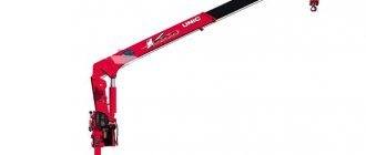
So, if you choose Italian Amco Veba special equipment for yourself, you will be able to order CMUs of the following series: mini, light, small-sized, medium, heavy. Such cranes operate using a hydraulic drive. The folding Z-boom sections are also extended by hydraulic cylinders.
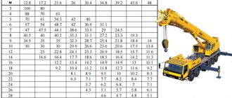
When selecting a specific model within the selected series, we recommend focusing on the load-height characteristics.
KMU, what kind of equipment is this?
A manipulator crane is a special piece of equipment that is a lifting mechanism installed on a vehicle. Due to its versatility, this equipment has several other names - hydraulic manipulator, thief, crane-manipulator, etc.
KMU is an abbreviation that stands for crane-manipulator unit. Structurally, the CMU device is a structure consisting of:
- slewing bearing;
- retractable supports or outriggers;
- main and additional booms, sometimes with an extension (in single file);
- lifting device;
- executive hydraulic cylinders;
- control station, in some cases a remote control is added.
Since crane-manipulator installations are most often placed on a vehicle chassis, they are sometimes confused with a truck crane. However, I would like to draw your attention to the fact that the CMU differs from a truck crane very significantly. These are different types of equipment designed to perform different tasks.
The main differences between a crane and a truck crane:
- Arrow. In the CMU, the first two or three sections (depending on the type of structure) have an elbow connection and only then comes the telescopic part. The truck crane has a telescopic boom starting from the first section.
- Operator's work. The truck crane operator, as a rule, works from a equipped closed cabin, while the crane-manipulator unit is controlled from the ground using levers mounted on the frame or from the remote control.
- Arrow length. As a rule, the reach of the CMU boom is less than that of a truck crane.
- The crane-manipulator does not have a counterweight and its lifting characteristics are determined by the support contour.
The name also hides the principle of operation of the crane unit - the operator manipulates the crane installation. Most often, its drive is carried out from the hydraulic system of the vehicle on which it is mounted. However, this scheme is not always possible. Then the crane can be equipped with its own electric motor.
Gas workers portal
Classification and technical characteristics of load-lifting cranes
A lifting crane is a lifting machine equipped with permanently installed lifting mechanisms, designed to lift and move cargo.
According to their design, cranes are divided into groups:
- bridge type , which include bridge, gantry and bridge loaders,
- jib type, which includes tower, portal, railway and other cranes in which the boom equipment is placed on a running device (automobile, pneumatic, on a special chassis, crawler, tractor);
- cable type - cable and bridge cable;
- cranes - stackers - bridge and rack with machine drive.
Based on the design of the load-handling device, cranes are divided into: hook cranes, designed to work with various piece loads; grab - for working with bulk materials; magnetic - for moving steel and cast iron loads; ticks - for boxes, barrels, bags, etc.; traverse, equipped, for example, with vacuum grippers, pincers; cranes with automatic grippers - spreaders, for transporting containers.
Depending on the type of movement, lifting cranes are either stationary or mobile.
According to the design of the chassis, they are divided into: rail, pneumatic, automobile, wheeled, roller, on a special chassis, on a short-wheelbase chassis and tracked, tractor.
Parameters of jib self-propelled cranes K - track, Vk - crane base, Vo - longitudinal distance between supports, Ko - transverse distance between supports, l - boom length, H - hook lifting height, h - hook lowering depth, r - dimensions of the rotating part of the crane .
According to the type of mechanism drives, cranes come with electric, mechanical and hydraulic drives.
According to the degree of boom rotation, cranes are divided into: full-rotary, part-rotary, non-rotary.
According to the method of supporting the crane runway, cranes are divided into supporting and suspended.
The main technical characteristics of load-lifting cranes include: lifting capacity, load moment, boom length, hook reach and lifting height, load lifting and landing speeds, crane movement, load trolley movement, etc.
Load capacity is the maximum permissible weight of the working load for lifting, which the crane is designed for under given operating conditions. The lifting capacity includes the weight of removable lifting devices installed on the crane.
Load moment is the product of the reach of the load-handling element and the crane’s lifting capacity
M = R * Q,
where: M - load moment; R — reach, m; Q - load capacity, i.e.
Arrow length is the distance from the center of the arrow heel to the axis of the head block.
Reach of a hook or other load-handling device is the horizontal distance from the axis of rotation of the rotating part of the crane to the axis of the hook or other load-handling element of the crane.
The lifting height of the hook is the distance from the crane runway level or the crane parking level to the center of the hook mouth, which is in the upper working position.
Jib crane track - the horizontal distance between the axes of the rails or the axes of the crane's rolling path.
A defining characteristic for the safe operation of jib cranes is their resistance to capsizing . There is a distinction between load stability, i.e. the ability of a crane during operation to withstand the action of all loads tending to tip it forward - towards the boom, and its own stability, i.e. the stability of the crane in an inoperative state in the absence of payloads and possible tilting back - to the side opposite to the arrow.
One of the main conditions for safe work on truck-mounted cranes is load and self-tip stability, which depends on the weight of the crane and the size of its support contour. When the crane operates on outriggers, the support contour is formed by the centers of their supporting surfaces (Fig. a), and without outriggers - by the centers of the contact surfaces of the front and rear wheels with the surface of the platform (Fig. b). The straight line connecting the centers of contact of the support surfaces of the contour is tilting edge of the crane.
Freight, i.e. in the working position, the stability of the crane is characterized by the load stability coefficient, and in the non-working position - by the self-stability coefficient.
Schemes for calculating crane stability : a - cargo, b - own
Load stability coefficient - the ratio of the moment (Gb) created by the weight of all parts of the crane, taking into account the wind load and the slope of the working platform (a = 3°), to the moment (Qa) created the weight of the working load relative to tipping. It should not be less than 1.15. The load stability coefficient, calculated without taking into account wind load and the slope of the working site, should be no less than 1.4.
The self-stability coefficient, which should also not be less than 1.15, is the ratio of the moment (Gc) created by the weight of all parts of the crane, taking into account the slope of the working platform in the direction of overturning, to the moment created by the wind load relative to the overturning edge.
Load characteristics - the dependence of the crane's lifting capacity on its reach. Each brand of crane has its own load characteristics. Cranes whose lifting capacity changes with changes in reach must be equipped with indicators of the lifting capacity corresponding to the established reach.
Lifting capacity chart (a) and operating area (b) of the KS-4571 crane: 1 – 3 lifting capacity of a crane with boom lengths of 9.75;
15.75 and 21.75 m on outriggers, 4 – lifting capacity of a crane with a boom length of 9.75 m without outriggers Overhead cranes
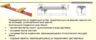
Overhead cranes are designed to serve mainly rectangular platforms. The most common overhead cranes are overhead cranes, gantry cranes and bridge cranes.
Overhead cranes (Fig.) are a structure of beams supported by trolleys that move along rail tracks. The mechanisms for lifting loads and moving the overhead crane trolley are located on the trolley itself. By design, overhead cranes are distinguished: one and two beam, manual and electric drive with a control cabin from the floor or a remote control. Depending on the number of spans, they can be single-span or multi-span.
The most widely used are general-purpose overhead cranes with an electric drive with a lifting capacity of 5 - 50 tons, a load lifting height of 12.5 m and a span length of 10.5 - 34.5 m. To move heavy loads, overhead cranes with a main mechanism lifting capacity of 80 to 630 t, auxiliary 20 - 80 t and load lifting height up to 34 m.
Bridge crane 1 - crane bridge, 2 - crane trolley, 3 - crane beam, 4 - hook suspension of the main lift, 5 - hook suspension of the auxiliary lift, 6 - cabin
. The lifting capacity of bridge cranes is indicated by an integer or fractional number: the numerator indicates the lifting capacity of the main, and in the denominator - the auxiliary lifting mechanism (for example, 20/5, 32/5, 50/12.5).
Gantry cranes (Fig.) consist of a crossbar, hoist or crane trolley with a mechanism for lifting the load and moving the trolley and two supports resting on the running trolleys of the crane. These cranes have no significant differences in design. They differ from each other in the following indicators: purpose, span, presence of consoles, load-handling devices.
The following devices and safety devices are installed on overhead and gantry cranes for general purposes: travel limiters of the crane and crane trolley; hook suspension lift limiter; sound signal; device for protection against loss of one of the phases. When the load lifting electric motor is turned off, this device removes voltage from the brake electromagnet coils or motor windings.
Gantry cranes : a- two girder;
b – single beam; 1 – movement mechanism; 2 – control cabin; 3 – trolley, 4 – support; 5 bridge (crossbar) 6 - electric hoist. In addition to those listed above, overhead cranes are additionally equipped with the following instruments and safety devices:
- load limiter (if its overload is not excluded due to production conditions)
- electrical blocking devices (blocking the entrance to the crane cabin from the landing platform and the hatch cover for exiting to the bridge deck);
- interlocking devices for automatically relieving tension from the crane when opening doors (hatches), when entering the control cabin and exiting the bridge gallery;
- support parts installed in case of damage to the axles of the running wheels.
The following are additionally installed on gantry cranes:
- anti-theft devices to prevent theft of the crane by the wind (if there are automatic devices, manual ones must be provided);
- anemometer, installed on gantry cranes with a span length of more than 16 m. If the wind speed reaches the limit state, the sound signal is activated.
- grips - to prevent theft of the crane when parked. Upon completion of work, the crane operator must install all hand grips.
Tower cranes
Tower cranes a – with a rotating tower and shunting boom KB-60;
b – with a fixed tower and a cargo trolley moving along a beam boom KB-674: 1 – running trolleys; 2 – ballast; 3 – mounting mast; 4 – tower; 5 – spacer; 6 – counterweight; 7 – cargo winch; 8 – head; 9 – cabin; 10 – boom; 11 – cargo trolley; 12 – hook suspension; 13 — rotating support; 14 – portal; 15 – running frame. A tower crane is a rotary crane with a boom attached to the top of a vertical tower. Tower cranes are divided into: mobile, moving along ground crane tracks; attached with a tower attached to the structure being erected; self-elevating, resting on the frame of the structure.
According to their design, tower cranes are divided into cranes with rotating and fixed towers.
According to the method of changing the hook reach, a distinction is made between tower cranes (Fig.) with a controlled (shunting) boom and cranes with a load trolley moving along a beam boom.
In cranes with a slewing tower, the slewing bearing is usually located at the bottom, directly on the running gear of the crane.
In fixed tower cranes, the slewing bearing is located at the top of the tower. All are controlled by the driver from the cab, which is usually located at the top of the tower. The load is lifted using a cargo winch, a cargo rope and a hook suspension. Changing the hook reach is carried out either by changing the angle of the boom, or by moving the load trolley.
The designation of crane brands includes the following characteristics: purpose; size group; serial number of the basic crane model; designation of the next modernization; Climatic performance. Tower cranes are assigned various letter designations, for example: MSK - mobile folding crane, BK - tower crane, ABKS - truck-mounted tower crane for rural construction. The numbers indicate the load capacity (for example, ABKS-5), load capacity and reach (MSK-10-20) or load moment (BK-1000).
Section 2.12 of the Rules establishes requirements for the installation of safety instruments and devices on tower cranes.
Tower cranes must be equipped with operating movement limiters to automatically stop:
- lifting mechanism of the load-handling body;
- mechanism for changing departure;
- mechanism for moving the crane and its load trolleys.
Limiters for travel mechanisms must ensure that the motors of the mechanisms are turned off at a distance to the stop not less than the full braking distance.
Tower cranes must be equipped with lifting capacity (load moment) limiters that automatically turn off the load lifting and outreach mechanisms in the event of lifting a load whose weight exceeds the crane's lifting capacity for a given outreach. After the load limiter has been activated, there should possibly be a lowering of the load or activation of other mechanisms to reduce the load moment.
Tower cranes with a lifting capacity of more than 5 tons must be equipped with recorders of their operating parameters.
Cranes with a height to the top of the head of more than 15 m must be equipped with an anemometer that automatically turns on an audible signal when the wind speed specified in the passport for the operating state of the crane is reached.
Cranes and cargo trolleys moving along a crane track must be equipped with support parts in case of breakage of the wheels and axles of the running devices.
In addition, tower cranes must have protection against falling loads and booms in the event of a break in any of the three phases, anti-theft devices, a tower extension limiter, a lightning rod and side light alarm, an audible signal, and for cranes with variable boom reach, a device that prevents the boom from tilting back.
Jib cranes
A rotating crane, in which the boom or tower-boom equipment is mounted on a rotating platform placed directly on the running device (automobile, pneumatic, on a special chassis, tracked, tractor, etc.) is called a jib crane.
According to the type of suspension of boom equipment, self-propelled cranes are divided into cranes with a flexible suspension, in which the boom is held and changes the angle of inclination using ropes, and cranes with a rigid suspension, in which the boom is held and changes the angle of inclination using hydraulic cylinders or screw mechanisms.
Jib cranes are assigned an index, in most cases consisting of two letters and four numbers. The letters KS stand for “General Purpose Jib Crane”. The numbers that are written after the letters characterize the basic data of the crane:
- the first digit indicates its carrying capacity (1-4t; 2-6.3t; 3-10t; 4-16t; 5-25t; 6-40t; 7-63t; 8-100t);
- the second digit indicates the crane's undercarriage (1 - crawler, 2 - tracked with an increased surface, 3 - pneumatic wheels, 4 - on a special automobile-type chassis, 5 - truck chassis, 6 - tractor, 7 - trailed undercarriage);
- the third digit indicates the design of the boom equipment suspension (6 - flexible boom suspension, 7 - rigid boom suspension, 8 - telescopic boom);
- the fourth digit indicates the serial number of the crane model.
For example, a crane brand KS-4362 is deciphered as follows: crane with a lifting capacity of 16 tons, pneumatic wheels, flexible boom suspension, model serial number 2.
Sometimes, after the numbers in the index, letters are indicated that indicate the modernization of the crane (A, B, C, etc.) and climatic use (HL - northern, T - tropics, TV - humid tropics).
Special jib self-propelled cranes or those manufactured jointly with foreign companies may have a different indexing.
Truck cranes KTS-ZG (a) and ABK-4A (b) with tower-jib equipment
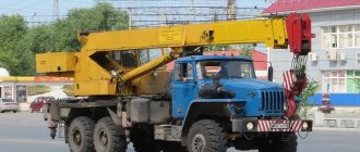
Jib cranes on a truck chassis
The cranes are mounted on the chassis of standard vehicles (Fig.) and consist of a fixed and rotating part, connected to each other by a slewing support device, which allows the rotating part to rotate relative to the fixed part.
Truck crane KS - 3574 1 – hook suspension;
2 – boom; 3 – chassis of the base car; 4 – boom stand; 5 – hydraulic tank; 6 – spare wheel; 7 – driver’s cabin; 8 – rotating frame; 9 – lining; 10 – thrust bearing; 11 – rotating support; 12 – support frame; 13 – locking mechanism (stabilizer); 14 – facing; 15 – outrigger. To limit loads on the chassis and ensure stability during operation, the cranes are equipped with outriggers and locking mechanisms (stabilizers) for the rear axle wheels. Truck cranes have a high travel speed, which allows them to be used in areas with small volumes of work located at a considerable distance from each other.
Truck cranes must be equipped with instruments and safety devices in accordance with section 2.12. Rules for the design and safe operation of load-lifting cranes.
1. Working movement limiters for automatic stopping:
- a mechanism for lifting the load-handling member in its upper and lower positions;
- mechanism for changing the boom extension;
- mechanism for turning the rotary frame of the crane;
- telescopic boom extension mechanism.
2. Crane lifting capacity (load) limiters that automatically turn off the mechanisms for lifting loads and changing the reach in the event of lifting a load whose weight exceeds the lifting capacity for a given reach by more than 10%. For cranes with two or more load characteristics, the limiter must have a device for switching it to the selected characteristic.
After the limiter is activated, it should be possible to lower the load or activate other mechanisms to reduce the load moment.
3. Coordinate protection that prevents collisions with obstacles when the crane is operating in cramped conditions.
4. Load capacity indicator corresponding to the reach. It must be clearly visible from the crane operator's workplace.
In modern microprocessor limiters (ONK-140, ONK-160, etc.), the functions of coordinate protection and load capacity indicator are performed by an electronic unit.
5. Crane angle indicators (inclinometers, alarms)
6. Dangerous voltage alarms and devices for automatically turning off the mechanisms for lifting, turning and extending the boom at a safe distance from the crane to the power line wires.
7. Recorder of crane operating parameters.
8. Sound signal.
Pneumatic cranes
They are used for construction and installation work. They have a running gear in the form of a special chassis, the width of which is greater than that of truck cranes. The crane is mounted on outriggers using double-acting hydraulic cylinders. On the rotating part of the crane there are mechanisms for moving the crane (diesel-electric multi-motor drive), turning the boom, changing the reach, lifting and lowering the load. Cranes are produced with a lifting capacity of 16 - 100 tons and booms with a length of 12.5; 17.5; 22.5 and 27.5 m. Pneumatic wheel cranes are equipped with instruments and safety devices, like a truck crane.
Jib cranes on crawler undercarriages
Cranes of this type are used for the installation of structures, heavy equipment, as well as for loading and unloading operations. The cranes have high maneuverability and do not require the construction of special roads. They can move over short distances at a speed of 3 km/hour. Such cranes are equipped with electric and diesel-electric drives. The cranes move by means of two crawler trolleys. Available with boom and turret-boom equipment. By using standard sections, the crane can be equipped with an extended jib boom. The cranes are equipped with instruments and safety devices in accordance with the requirements of section 2.12. Rules
Pneumatic tire( s)
Crawler ( b ) crane 1 – chassis;
2 – counterweight; 3 – rotating part; 4 – outrigger; 5 – boom; 6 – jib; 7 – rotating support; 8 jib pulley; 9 – hook suspension. Railway cranes
Jib-type cranes mounted on a special platform moving along a railway track. They are produced with a lifting capacity from 6 to 100 tons. Cranes must be equipped with instruments and safety devices, like jib self-propelled cranes, including recorders of their operating parameters. They are used for loading and unloading operations, mainly at railside warehouses and when performing installation, repair and restoration work.
Cable taps
These cranes are designed to service large production areas (lumber yards, concrete plants, etc.)
They consist of two towers with a support rope stretched between them, along which a cargo trolley moves. Depending on the nature of the work performed, cable cranes are either stationary or mobile. Mobile cranes, in which both towers move along adjacent tracks, serve rectangular platforms. If one tower is stationary and the other moves along a ring rail, then such a crane serves the area in the form of a sector, and it is called radial. Cable cranes equipped with hook hangers or grabs have a lifting capacity of 3-25t, sometimes 150t. Crane spans are generally 300-600 m, sometimes 1000 m. The height of the towers is 25–40 m, sometimes 60-70 m. The lifting height of the load ranges from 150 to 205 m or more. The cable cranes are controlled from a cabin, which is placed on a moving tower, at a height of 20-25 m from the supporting surface. The cable tap shown in Fig. 3.10, has towers moving along parallel crane tracks. A supporting rope 1 is stretched between the towers, along which a cargo trolley 5 moves with the help of a traction rope 2. The trolley is equipped with blocks of a lifting rope 4, one end of which is fixed to the cargo trolley, and the other to the drum of the load lifting mechanism. The mechanism 9 for lifting the load and moving the trolley, the control cabin 8 are installed on one of the towers. To limit the sagging of the lifting and traction ropes, supports 7 are installed on a special rope 3. The crane is equipped with a hook suspension 6.
Cable tap
Cranes – stackers and – pavement; Cranes - stackers b - rack
Cranes - stackers
Cranes - stackers are divided into bridge (supporting and suspended) and racking. They have the following versions: OP - supporting bridge, controlled from the floor, with installation of rail tracks on racks or columns of the building; are used for transporting and processing palletized cargo in warehouses: OK - supporting bridge, controlled from the cabin with the installation of rail tracks on the building columns; used for transportation and processing of packaged goods and rolled metal; OKD - supporting bridge, for long loads, controlled from the cabin, with the installation of rail tracks on the columns of the building; used for transportation and storage of rolled metal products in specialized warehouses; SA – rack automatic support, controlled from the cabin with installation in buildings whose floors are supported by racks; used in warehouses for transporting goods packed in standard containers. The lifting capacity of overhead cranes - stackers - is 5 tons, and support cranes - up to 125 tons.
An overhead crane - stacker (Fig. a) is a crane bridge 1 along which a trolley 2 carrying a rotary column moves. Using a rope lifting mechanism mounted on a trolley, a forklift with a load-handling device, usually made in the form of a fork 4, moves along it. A crane operator’s cabin is installed on the forklift. The crane moves along 5 rails mounted on 6 racks or columns of the building.
The rack crane - stacker (Fig. b) is a trolley 7, which moves on rails along the racks. A loading platform 9 with an operator’s cabin and a retractable load gripper 10 moves along the vertical guides of the columns 8.
Stacker cranes must have the following safety and locking devices.
Load limiter and rope slack limiter; limit switches for limiting the extreme positions of the crane, forklift, trolley, load-handling device; limit switches for switching from operating speeds to setting mechanisms for crane movement; emergency switch for the upper position of the forklift; interlocks that prevent the activation of mechanisms if the emergency switch for the upper position of the forklift is activated, if the cabin door is not closed.
Questions for self-control
1. What is a lifting crane?
2. How are cranes classified according to their design?
3. What is the lifting capacity of a crane?
4. What size determines the reach of the crane boom?
5. What parameters of the crane determine its load characteristics?
6. What are the main parts of a truck crane lifting unit?
7. What parameters determine the designation index for truck cranes?
8. What factors reduce the stability of a truck-mounted crane against rollover?
9. Under what operating conditions will the lifting capacity of a truck crane be greatest?
10. What are the main parts and mechanisms of a tower crane?
11. How do tower cranes differ in the design of their towers and booms?
12. How is tower and overhead cranes powered by electric current?
13. How are gantry cranes classified by design?
14. What parts does a gantry crane consist of?
15. How are overhead and gantry cranes powered by electricity?
16. How are overhead cranes classified by design?
17. What are the main parts of an overhead crane?
18. What parameters are included in the indexes of overhead cranes?
19. What do the concepts, load and self-stability coefficients mean?
Types of cranes
The main criteria for the classification of CMUs are the type of base for installation, the design of the boom and, of course, the load capacity. In addition, the crane can have various attachments, for example, a grab for working with forests or a cradle for lifting people.
Where are the manipulators installed?
A crane-manipulator installation is a separate lifting equipment, a superstructure. The hydraulic manipulator can be placed on various bases. The most popular for CMU is the automobile chassis.
In addition, the manipulator is installed on:
- commercial vehicles, including trailers and semi-trailers;
- special pneumatic-wheeled chassis;
- railway platform;
- tracked base;
- tractors and harvesters;
- stationary technological site;
- tracked platforms;
- floating barges, river and sea vessels.
KMU boom design
When choosing a crane-manipulator installation, it is important what main work is planned to be performed with its help. The fact is that each of them has its own pros and cons.
There are two main types of CMU boom equipment: Z-shaped (articulated, articulated) and L-shaped (straight). The first is more popular in Europe, the second in Asia (Japan, Korea).
Advantages of Z-boom:
- Compact placement in the base due to the folding design.
- Effective when working with large, bulky and voluminous loads.
- Flexibility under difficult working conditions, for example, can “go around” an obstacle.
- Universal to use.
Advantages of L-shaped boom:
- Creates less load on the front axle of the vehicle chassis when placed behind the cab.
- Turns around faster to work on long arms and with heavy loads.
- High speed of work at a small radius.
Note!
Among the main disadvantages of the L-shaped boom is the limitation on the loading height of the body.
Classification of CMU by load capacity
Load capacity is one of the main indicators for cranes. However, there is no clear classification of crane-manipulator installations according to this indicator. In addition, some manufacturers subdivide the CMU according to the load moment - the product of the maximum load capacity and the boom reach. And even on this there is no agreement, for example, some consider manipulators up to 4 tm light, others up to 10 tm.
However, most users and owners of loader cranes adhere to the following classification:
- Small manipulators – up to 999 kg / 2.9 tm
- Light CMU – up to 2.9 tons / 10 tm
- Medium CMU – from 3 to 10 tons / 29.9 tm
- Heavy cranes – over 10 tons / 30 tm
This classification is also based on the requirements of Russian legislation. In particular, Gostekhnadzor standards classify mechanisms with a lifting capacity of up to 3 tons as manipulators, and above that as crane installations, which require the provision of additional documents for registration.
Terminological basics
What is a crane-manipulator anyway? The answer to this question is quite easy. This is a machine that is designed to lift loads. Such a machine consists of a crane-manipulator installation, which is installed on a running device or permanently.
A crane manipulator is a lifting device that contains boom equipment, load-handling bases, a control system, and, of course, a support frame.
A hydraulic manipulator is a lifting mechanism that works with hydraulic tools. This definition is used when declaring timber trucks, metal trucks, garbage trucks and other specific equipment where the equipment is used for handling materials.
The 1st section of the hydraulic manipulator boom is high, and the 2nd section is short, and it has a telescopic part. This does not allow them to be placed in a transport position, stowed behind the cabin. They are on a special support.
Reverse Z-type models are available. The top boom is placed on top and the load handle is found at the top. This allows the hydraulic manipulator to be compactly placed when stowed behind the cabin, but the low load moment limits their use.
There are many authors who do not support precise terminology, although it is necessary to some extent.
Crane capabilities
The crane allows you to load and unload cargo, move it (in the case of equipment installation on a mobile base), and install various structures. Installing various working equipment on the boom allows you to further expand the capabilities of the CMU.
Depending on the tasks, instead of a lifting hook the following can be installed:
- Cradle for lifting workers.
- Gripper for working with containers.
- Grab for bulk materials.
- Clamps for scrap metal, pipes, timber.
- Special devices for loading and unloading curb stones.
- Equipment for vehicle recovery.
- Pallet forks.
- Drilling equipment.
Additional Information!
If the boom cross-section is a polygon, then the strength will be higher compared to a round cross-section. A larger number of edges makes the structure stronger and more reliable.
Manipulators can be used for:
- loading and unloading of trucks, small vessels, railway cars;
- transportation of inventory, equipment, materials and tools;
- installation, dismantling and transportation of various equipment (machine tools, transformers, boilers, mini-power plants) and metal structures (advertising boards);
- evacuation of cars and other equipment (rollers, bulldozers, excavators, etc.), including those in faulty condition;
- installing poles, fences, fences and even planting trees.
All this allows the use of manipulators in various fields and industries.
Main areas of application for 20 ton manipulators
Freight transportation . Our vehicles successfully cope with transport tasks of high complexity, therefore they can be used to deliver goods for various purposes over medium and long distances.
Industry . Special equipment can be used to transport large equipment at industrial facilities. The kinematics of the manipulator allows it to be used in confined spaces, where a conventional truck crane is ineffective.
Construction . The vehicles in our fleet are capable of simultaneously transporting up to 20 tons of reinforced concrete products, metal structures and heavy equipment from the supplier’s base to the construction site.
Where is CMU used?
The most popular base for installing cranes is cars. A machine with a manipulator is the only association most people have. They are used in logistics, construction, oil and gas, logging industries, utilities, energy complex and when working with waste. But besides this, cranes are widely used on railways and at sea.
CMU for ships
The crane-manipulator installation does not take up much space during installation. This advantage of CMUs is used at sea, where compactness is important. They are used for loading vessels, as well as in fishing.
The crane mounted on the vessel performs not only loading and unloading, but also installation work. They are used for laying underwater cables, especially at shallow depths, cleaning the bottom, and transport work.
Of course, for operation on water, the installations are pre-treated with a special anti-corrosion compound. In addition, some of them are equipped with electric motors for autonomous operation.
Railway manipulators
Due to their flexibility, manipulators work more efficiently near power lines. In addition, they are universal equipment capable of carrying out not only loading and unloading operations, but also working with replaceable equipment.
Installed on a railway platform as part of repair teams, the CMU helps to change rails, sleepers, fill tracks, and also lift workers for repairs and laying a contact network.
Forestry industry
Manipulators work in forestry and logging. Equipped with a grab grip, the CMU easily carries out loading and unloading operations, placing workpieces on the whip carriers. A specially equipped operator position on the first section of the boom allows him to control the process from above, gaining excellent visibility.
In addition, with the help of a manipulator it is more efficient to remove fallen trees.
Housing and communal services and waste management
CMUs play an important role in housing and communal services and waste management. Loading container boats with waste into the machine is usually carried out using a hook. This device is also a type of CMU.
Also, some models of combined road vehicles are equipped with manipulators or hook grips for installing replaceable equipment on the vehicle chassis.
Construction and logistics
The manipulator can work effectively in cottage construction, combining loading, transportation and unloading of bricks, reinforced concrete slabs and other building materials. At the same time, there is no need to order the services of conventional truck cranes.
When solving logistics problems using vehicles equipped with CMUs, there is no need to use loading equipment. A loader crane can not only bring and remove cargo to the site, in some cases it can place it directly at the place of storage or use.
Choosing a CMU for a truck
Companies involved in the sale, installation and maintenance of CMU offer various delivery options. They can provide a ready-made option on the desired platform, or they can mount the equipment on the client’s chassis.
Crane-manipulator installations are mounted on domestic cars - GAZelle, GAZon, KamAZ, MAZ, as well as on almost all foreign cars. In addition, Korean and Japanese used Vorovayki remain in demand on the market.
When choosing a CMU, you should pay attention to:
- own weight of the installation;
- boom type and radius;
- work radius and turning angle;
- load capacity;
- load moment;
- lifting height.
It is worth remembering that maximum lifting capacity is achieved with minimum boom reach. Therefore, carefully study the load-height characteristics of the crane-manipulator installation.
All CMUs – L- and Z-types – are equipped with a telescopic boom. In most cases these are 3, 4 or 5-section models. In this case, booms with the same number of sections, the same length and cross-section may have different load moments. In many models of crane-manipulator installations, the sections extend one by one, but there is also equipment where the boom extends proportionally.
Important!
If the arrow telescopes proportionally, i.e. All sections extend simultaneously, the load moment will be lower than that of a boom with sequential extension.
It is not recommended to handle heavy loads on a proportional extension arm. This is because the last inner section of the boom is the thinnest and is designed for lighter loads. An excess on it can lead to deflection and, as a result, failure of the CMU.
It is worth paying attention to the arrow profile. The most common are four-, five- and six-sided. Whiter profiled sections provide straighter movement and allow for more accurate centering when telescoping.
It may be important to be able to install additional equipment - a hydraulic grip for piece goods and containers, a grab for bulk and small lumpy materials, a cradle for lifting people. A wide selection of replaceable working equipment for hydraulic manipulators will allow you to diversify the services offered and increase the income of the CMU.
Advantages of renting a 20 ton manipulator from our company
High quality technology. We provide technically sound manipulators equipped with all necessary rigging and load-handling devices.
Economical . The cost of renting special equipment justifies the transportation of every ton of cargo.
Wide geography of work . You can rent a 20-ton manipulator not only in Moscow or the Moscow region. If necessary, we will provide equipment for work in the regions of Russia.
If you would like more information about or submit a request, please use the feedback form or call our office.
The lifting capacity (measured in tons) indicates the maximum weight of the load that the manipulator is designed to carry. The load moment (measured in ton-meters) shows at what distance from the axis of the vehicle a load of a given mass can be placed.
Why is it convenient to work with cranes?
A machine with a manipulator is primarily a commercial vehicle. Therefore, it must generate income. Combining the functions of a crane and a truck in one special equipment allows you to save time and money, as well as differentiate risks.
Renting a CMU, for example, when building a cottage or low-rise building, will reduce costs. After all, in order to bring building materials you will not need to hire a separate truck for transportation and a team of loaders to unload them. And also a crane for lifting. All these operations can be easily performed by one person on a crane.
Author: Andrey Solomin
Share
Dependence of load capacity on boom radius
The load capacity of the manipulators is inversely proportional to the boom reach. The farther the cargo being transported is from the vehicle, the less weight the crane can lift. In this case, the law of leverage applies. For example, if a truck with a manipulator is located more than 10 m from the load, the declared load capacity may be reduced by approximately 3 times. At the same time, the length of the boom does not depend on the type of equipment in terms of lifting capacity: for light models, the length of the lifting element can reach 14 m, and for heavy ones it can be only 9–10 m.