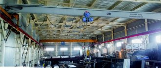
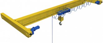
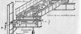
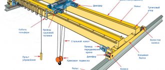
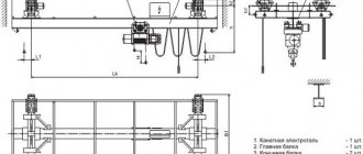
The overhead crane (Figure 2.1) consists of one or two main beams of the bridge 11, which can move on running wheels 3, which are installed in the end beams 4, along the crane tracks 2, laid on the projections of the upper part of the wall or columns of the workshop (overpass).
Figure 2.1 – General view of the overhead crane: 1 – driver’s (crane operator’s) cabin; 2 – crane runway; 3 – running wheel; 4 – end beam; 5 – flexible cable for power supply to the crane trolley; 6 – mechanism for auxiliary lifting of cargo; 7 – main load lifting mechanism; 8 – crane trolley; 9 – cable for hanging a flexible cable; 10 – platform for servicing trolls; 11 – main beam of the bridge; 12 – trolley movement mechanism; 13 – crane movement mechanism.
A crane trolley 8, equipped with a load lifting mechanism with a load-handling element, moves along the lower (suspended crane) or upper (support crane, characterized by a higher load capacity) belt of the bridge beams across the workshop span. Depending on the purpose of the crane, the trolley can accommodate different types of lifting mechanisms or two lifting mechanisms, one of which is the main one 7, and the second, with a smaller load capacity, is an auxiliary one 6.
The crane movement mechanism 13 is installed on the crane bridge; trolley movement mechanism 12 – directly on the trolley. All mechanisms are controlled from cabin 1, installed under the crane bridge, or via a remote control from the floor (less often).
The current to power the electric motors is supplied through trolleys mounted on the wall of the building, which are usually made of rolled angle steel. To supply current to the crane, sliding-type current collectors are used, attached to the metal structures of the crane, the shoes of which slide along the trolleys when the crane bridge moves. To service the trolleys on the crane, a special platform 10 is provided.
To carry out the current supply to the motors located on the trolley, trolleys made of round or angle steel are usually used. Their installation requires special racks on the platform running along the main beam. In the latest designs of overhead cranes, the current supply to the trolley is carried out using a flexible cable 5. In this case, a cable 9 is stretched between two racks installed near the end beams, to which a flexible cable is suspended in a spiral on special hangers, folding when the trolley approaches one end of the bridge , and when the trolley approaches the other end of the bridge, it stretches with a slight sag. The use of a flexible current supply simplified the design, increased operational reliability and reduced the weight of the crane, as it made it possible to eliminate the racks and platform for their placement and maintenance.
The main parameters of the overhead crane are:
- lifting capacity – the maximum weight of cargo that the crane is designed to lift and move under given operating conditions. The load capacity includes the mass of removable lifting devices and containers used to move the load;
- span – the horizontal distance between the axes of the crane track rails, characterizing the size of the area served by the crane;
- lifting height – the distance from the crane parking level to the load-handling device in the upper position;
- lowering depth - vertical distance from the crane parking level to the load-handling member in the lower working position;
- base – the distance between the axes of the supports (running trolleys) of the crane, measured along the path.
Classification groups (operation modes) of load-lifting cranes and machines (A1 - A8) and their mechanisms (M1 - M8) are determined in accordance with Appendix 1 NPAOP 0.00-1.01-07 “Rules for the design and safe operation of load-lifting cranes” and are indicated in the passport of the load-lifting crane or machine .
The operating mode of the crane generally depends on the class of use (U0 - U9), which is characterized by the maximum number of cycles for a given service life, and the load mode (Q1 - Q4).
The operating mode of the mechanism depends on the class of use (T0 - T9), which is characterized by the total duration of use of the mechanism, and the load mode (L 1 - L 4).
The load mode is characterized by the value of the load distribution coefficient, which is determined by the formula given in Appendix 1 of NPAOP 0.00-1.01-07 “Rules for the design and safe operation of load-lifting cranes” [1].
Load lifting mechanism
Load lifting mechanisms are located on the crane trolley.
Load lifting mechanisms are located on the crane trolley. All trolleys are equipped with several load lifting mechanisms. This is for heavy, medium and very light loads.
Lifting mechanisms depend on the purpose of the crane, what loads it lifts, to what height and with what weight. For example, if a load is lifted using hooks, then one load lifting mechanism is used.
This mechanism requires the presence of:
- brakes;
- drum;
- cargo rope;
- blocks;
- gearbox;
- transmission shaft;
- electric motor with drive.
Lifts designed for heavier loads have the same design, only they may additionally have one more gearbox.
If the load is lifted to a greater height, the length of the rope that is wound onto the drum may increase. It will be significantly larger than the rope that will be wound in one layer. If it is still necessary to use such a long rope, then at such a moment special mechanisms are used, which are called rope-layers. Thanks to such rope layers, the entire long rope will be evenly wound onto the drum and a beautiful layer of rope will be obtained. In turn, they come in screw, crank, cam and other rope-laying types.
content .. 81 82 87 ..9.1.
BASIC DIAGRAMS OF MOVEMENT MECHANISMS for lifting machines - part 1
Travel mechanism with drive wheels
. The movement mechanism with drive wheels consists of an engine, a transmission system and a chassis with running wheels (rollers). The movement mechanisms of trolleys and cranes can be manual or machine driven.
Manual movement mechanism
. This travel mechanism is used on cranes used in warehouses and production areas with a limited volume of work. Typically, the lifting capacity of such cranes is 15-20 tons, the span is no more than 16.5 m. In overhead cranes with a manually driven travel mechanism, depending on the lifting capacity and span, the bridge can be made of a single-beam I-beam profile or a double-beam with a four-roller trolley. The trolley movement mechanism (Fig. 9.1) is mounted on a frame 2, supported by two drive 3 (drive) and two non-drive 1 (driven) wheels.
The drive wheels are driven into rotation through a gear 4 from the traction wheel 5 with a traction chain or using a handle.
Recommended values of applied forces and peripheral speed of the handle are given in table. 3.1.
Rice. 9.1. Manual movement mechanism
Movement mechanisms with electric drive of trolleys and bridges
. These mechanisms consist of an electric motor, intermediate gears, and a chassis with drive and non-drive wheels. In modern cranes, movement mechanisms differ in the use of a drive with a gearbox; using running wheels with removable axle boxes; connecting shafts, including high-speed ones, mainly with gear couplings that do not require high precision assembly.
The most typical drives for the trolley movement mechanism are drives with a centrally located gearbox (see Fig. 9.3, b).
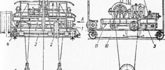
Drives with mounted gearboxes have also become quite widespread (Fig. 9.2). A flange electric motor 1 is attached to the mounted gearbox 2 of this mechanism, the torque from which is transmitted through gears to the hollow output shaft 8 and from it to the shafts of the drive wheels 9. The second drive wheel is connected to the shaft of the first by an equalizing transmission shaft 6 with two gear coupling halves 7 Brake pulley 4 of brake 3, mounted on bracket 5, is mounted on the intermediate or high-speed gearbox shaft. The reaction torque that occurs when the trolley moves is perceived through the gearbox housing by thrust bolts 10. The movement mechanism with a mounted gearbox does not require special support posts on the trolley frame for the gearbox and electric motor. In addition, this travel mechanism is compact and easy to install. However, when replacing the drive wheels on this mechanism, it is necessary to dismantle the gearbox, which complicates repairs.
The use of mechanisms with a mounted gearbox is not practical for trolleys with a large load capacity (more than 20 tons), since in this case the size and weight of the mounted gearbox increase disproportionately and become unacceptable.
Rice. 9.2. The mechanism of movement of the trolley with a mounted gearbox
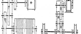
Rice. 9.3. Mechanisms of movement of overhead cranes: a. b. c - with transmission shafts, respectively, low-speed, medium-speed and high-speed; g - with separate drive
content .. 81 82 87 ..
Development of an overhead crane with a lifting capacity of 10 tons and a span of 18 m.
idfer87
July 6, 2020
- 0
1 802
In the course work, the mechanism for lifting and moving a cargo trolley and crane is calculated. Drawings of the overhead crane, trolley and control cabin were completed. Load capacity - 10 tons. Speed - 0.12 m/s. Lifting height - 8 m.
Overhead crane drawings
Lifting mechanisms. EI-9011 series frequency converter in variable frequency drive
Load lifting mechanisms using an electric drive are installed on all lifting machines. Their general design is typical not only for cranes and elevators, but also for special-purpose machines, in which the direction of the force application vector from the load may coincide with the direction of rotation of the electric motor rotor.
The simplest version of the mechanism is a cargo winch. This is a machine for lifting loads using a rope wound on a drum with a hook in the form of a hook.
Basic kinematic diagram of the lifting mechanism
Electric drive of the lifting mechanism
The most common electric motor for the lifting mechanism is an asynchronous electric motor with a squirrel-cage rotor. Despite the simplicity of control (direct start), it has significant disadvantages:
- high starting currents,
- large dynamic loads at startup.
To some extent, they can be eliminated by using an electric motor with a wound rotor. But a new disadvantage appears - bulky power switching equipment.
The highest performance indicators can be achieved by using a variable frequency drive, namely:
- reduce starting currents to the rated level,
- reduce dynamic loads to the design level,
- smoothly adjust rotation speeds over a wide range.
Application of EI-9011 series inverter to control the lifting mechanism
When choosing a Vesper frequency converter, first of all you need to take into account the type of gearbox of the lifting mechanism. There are 2 main types:
- cylindrical,
- worm.
The difference between these gearboxes is that the cylindrical gearbox is double-sided, i.e., torque is transmitted both from the input shaft to the output shaft, and vice versa - from the output shaft to the input; and the worm is one-sided. The latter is installed less frequently - due to low efficiency and increased wear.
In lifting mechanisms with worm gear
It is possible to use any Vesper frequency converter of the EI, E3, E4, E5 series. But we will not consider the use of VFD in such a mechanism - due to the lack of features of its operation.
For lifting mechanisms with helical gearboxes
It is recommended to use frequency converters of the EI-9011 series, due to the presence of:
- A powerful central processor that allows you to create software for vector mode with high precision characteristics and wide functionality.
- Two vector modes: open-loop and with speed feedback sensor.
- Wide speed control range: 1/100 in normal vector mode and 1/1000 in closed-loop vector mode.
- Vector mode with feedback, which provides M=100% at almost zero engine speed.
The previously presented kinematic diagram of the lifting mechanism is optimal for control from the EI-9011 frequency converter. The mechanism contains a braking device (3), which is not structurally connected to either the electric motor or the gearbox. It has independent control of the electrical signal.
With a frequency converter, the structure will look like this:
Let's consider the simplest scheme for controlling the drive of a cargo winch with a low-power electric motor - up to 8 kW:
For such an application, as a rule, the inverter operating mode “Vector in an open-loop system” is sufficient.
Why him? Because it allows you to control engine rotation over a wider range of speeds than the scalar mode. This is especially important at the lower end of the range, where it is necessary to provide the rated torque on the motor shaft at the lowest possible rotation speed. The lower the value of the inverter output frequency at which the motor begins to rotate and has a rated load on its shaft, the less the dynamic (shock) load on all parts of the lifting mechanism.
Programming EI-9011 series inverter to control the lifting mechanism
To program the inverter, you must connect it to a 3F, 380 V, 50 Hz power supply network. Accordingly, the electric motor with which you are supposed to work should also be connected to the inverter. Programming is done from your own control panel.
The vector operating mode requires mandatory auto-tuning of the inverter with the used electric motor. It should be done every time the engine is replaced.
Important Note
: During the auto-tuning process, the inverter determines a number of motor parameters while the latter is rotating. Therefore, to correctly determine the parameters, the motor shaft must be free - there should be no excess attached mass on it.
After applying the supply voltage, in the main software menu you need to select the “Initialization” section. In this section:
- Perform initialization (return the values of all parameters to the factory settings).
Parameter A1-03=2220.
- Select the operating mode - “Vector in an open-loop system”.
Parameter A1-02=2.
- Determine the level of access to parameters - “Advanced”.
Parameter A1-01=4.
Selecting other menu sections and parameters is done in the same way.
Programming can also be done using the inverter control panel. All information is displayed on the remote control display in an accessible form and with comments in Russian.
Next step: in the main software menu you need to select the “Auto Configuration” section. In this section, you should follow all instructions for entering engine parameter values and start the autotuning process. If after completion there are no error messages on the control panel display, you should proceed to programming.
Next, in the main software menu, select the “Programming” section. The list of its parameters is determined by the following conditions:
- Control of the operation of the inverter (person or automated control system).
- Control of the operation of the mechanism by the inverter.
For the application under consideration, the operation and control algorithm will be as follows:
When a command is given to move up or down, the inverter issues a command to turn off the brake (unfreezes the mechanism), and then starts rotating the motor from the minimum frequency. During operation of the winch, you can adjust the rotation speed and, accordingly, the linear speed of movement of the hook with a load, choosing the optimal one.
Let's return to the electrical diagram of external connections to the inverter.
Terminals 1 and 2 have fixed start functions in forward and reverse direction respectively.
After power is supplied to the inverter, the type of control is remote: the light indicators UPR and REG light up. Parameters b1-02 and b1-01 are responsible for this state, i.e. The inverter is already configured for external commands “START” and “SPEED CONTROL”.
The winch brake will be controlled by a multifunctional discrete output: terminals 9-10. At the beginning of rotation, after the “START” command is given, the internal relay contacts close terminals 9-10 and provide a signal to control the winch brake system. This mode is provided by the discrete output function “During rotation”.
In combination with the DC braking mode at start-up, it is possible to create torque on the motor shaft at a minimum output frequency, at which there will be no loss of control and dynamic loads will be minimal.
The DC braking process at start is determined by the following parameters:
- V2-01 - frequency of switching on DC braking current.
- V2-02 — braking current level.
- B2-03 - DC braking time at start-up.
When the START command is given, DC braking of the motor is activated, but the brake is not yet released. During the braking time, the motor is pre-magnetized, and by the time the brake is turned off, an initial torque has already been created on its shaft. The following timing diagrams explain this:
When lowering a load, the direction of rotation of the motor shaft coincides with the direction of the force vector, which is determined by the mass of the load, and this force tries to increase the speed of rotation of the motor shaft. Thus, the engine switches to generator operating mode.
The EMF generated by the motor in this mode enters the inverter, increasing the voltage on the DC link. To prevent emergency stops of the drive due to voltage overload, a braking resistor is provided. It connects to the DC link when the DC bus voltage reaches a critical value and dissipates excess electricity into heat.
Summarizing the above, we can create a minimum list of parameters with specific values for programming operating modes and controlling the VFD of a cargo winch:
- A1-03=2220,
- A1-02=2,
- A1-01=4,
- B2-01=0.5,
- B2-02=50.0,
- B2-03=1.0,
- H2-01=37.
The considered example of a VFD for a cargo winch using the Vesper VFD of the EI-9011 series can be used as a base one for the design of more complex lifting mechanisms with improved performance characteristics.
Belyakov Alexander Leonidovich
Lead engineer "Vesper"
How does the braking process occur and why do overhead cranes need brakes?
The principle of operation of the braking system is quite simple. In order to stop the movement of the mechanism, it is necessary to convert the kinetic energy that it loses during movements into thermal energy. The easiest way to do this is through friction, so in the first brakes a special pad was pressed against the wheel, stopping it. Modern systems make it possible not only to stop the mechanism, but also to collect all the lost energy into storage devices or batteries for further use.
The importance of this mechanism is due, among other things, to the fact that the overhead hoisting crane, for all its massiveness and large dimensions, has good mobility and a high frequency of operation cycles. This means that in a certain unit of time the crane is capable of performing a large number of operations, and therefore the start-braking speed must be quite high. Therefore, it is so important that all elements of the braking system work smoothly and properly.
Project of an 8 t overhead crane trolley.
mcdien
November 27, 2020
- 0
1 125
In the course project, an overhead crane trolley with a lifting capacity of 8 tons was designed, during the development of which preliminary and verification calculations of assembly units of mechanisms were carried out, and loads were calculated. The layout of the lifting and moving mechanisms has been designed. For design they used both standard products and assembly
Overhead crane drawings