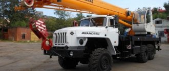
The KS-6471 truck crane is a diesel-hydraulic construction equipment, the components of which are rotating mechanisms, working equipment (targeted action) and various running devices. Cargo boom devices are installed on the frame frame of the rotating unit. There are also other technical (mechanical) components, consisting of boom winches, a turning device, an oil tank, an operator's cabin, hydraulic equipment and a counterweight.
Technical and load-height characteristics of KS 6471 truck cranes
In the transport position, the machine has a length of 15.36 meters, a height of 3.8 meters, and a width of 2.5 meters. The load characteristics of the KS 6471 truck crane allow it to have a load moment of 1370 (140) kn.m. (tf. m), lift up to 40 tons of various loads. The hook of the truck crane rises to 10.6 meters. The greatest value of the lowering depth, if the multiplicity of the tackle is 10 units, reaches 10 m, and if the multiplicity of the tackle is 6 units, it is equal to 23 meters. The boom device, with an outreach varying from 3.5 to 9 meters, has a length of 34.5 meters.
The rotary unit units operate from separate hydraulic motors powered by pumping mechanisms with a motor that operate from an internal combustion engine. The cargo winch is powered by a hydraulic motor located in the drum box, connected to the gearbox. The winch has a roller device that places rope elements on the drum mechanism, preventing it from unwinding arbitrarily when the hook suspension is lowered to the ground.
The design of the auxiliary hoist winch is similar to that of the main hoist component, but has a different rope volume. On the KS 6471, the device that raises and lowers the boom consists of two copies of double-acting hydraulic cylinders, on which reverse controlled valve baffles are installed, which prevent the boom, tilting in the range of -2-+87 degrees, from lowering after a pipeline rupture.
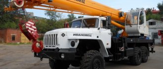
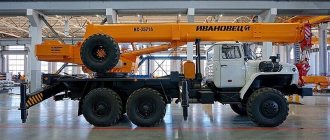
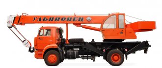
Features of the legendary equipment - Yanvarets truck cranes
The power unit of the Yanvarets truck crane includes a motor unit of the YaMZ-236 type, a gearbox of a pump drive device, as well as a group of 3 copies. The working equipment includes a 10.7-meter telescopic boom, which can be extended up to 25 meters. It is allowed to install an 8.5-meter unguided jib on it. Jib booms of 8.5, 15 and 20 meters in length, which can be steered, are mounted on boom jigs of the appropriate length. If the main boom becomes vertical, the equipment can be considered a tower boom.
The running unit of the KS 6471 truck crane is an independent unit with 4 axes, two copies of driving bridge elements, equipped with separate control systems (monitoring systems). The two axles located at the front are steerable, and the single axles are equipped with spring load softeners. The two dual drive axles located on the rear bogie are equipped with a rigid suspension that acts as a balancer.
On the chassis of a truck crane with a lifting capacity of 40 tons there are two independent braking mechanism systems, thanks to which the crane is braked if one of them breaks down. The car also has a hand brake that is activated when the vehicle is parked. The steered wheels are turned by hydraulic boosters, which operate from two separate pumping mechanisms. One of them is driven by an engine, and the emergency second is driven by a driving axle device.
| Crane KS-6471 on a special automobile-type chassis description and technical characteristics |
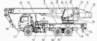
The KS-6471 crane is a diesel-hydraulic crane with a lifting capacity of 40 tons, consisting of a rotating part, working equipment and a running gear. The rotating part includes a frame on which cargo booms (main and auxiliary lifting), boom winches, a turning mechanism, an oil tank, a cabin with a control station, hydraulic equipment and a counterweight are mounted.
| Crane on special chassis of automotive type KS-6471 |
The rotating part mechanisms are driven by individual hydraulic motors, which are powered by a pumping unit with an internal combustion engine. The cargo winch is driven by a hydraulic motor connected to a gearbox mounted inside the drum. The winch is equipped with a roller that allows the rope to be laid on the drum and prevents the rope from unwinding arbitrarily when the hook suspension is lowered to the ground. The design of the auxiliary hoist winch is similar to the main one and differs only in its rope capacity. The boom lifting (lowering) mechanism consists of two double-acting hydraulic cylinders. The cylinders are equipped with controllable check valves that prevent the boom from lowering when pipelines rupture. The boom inclination varies from -2 to +87°. The power plant consists of a YaMZ-236 internal combustion engine, a pump drive gearbox and a pump group, including three axial piston pumps. The working equipment includes a main boom 10.7 m long, extendable using telescopic sections up to 25 m. An unguided jib 8.5 m long can be mounted on a boom 25 m long. Steerable jib 8.5 m long; 15 and 20 m are installed on booms 15 long; 20 and 25 m. When the main boom is brought to a vertical position, the equipment can be equated to a tower boom.
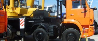
| Transport position of the crane KS-6471 |
The crane running gear is an independent four-axle unit with two drive axles with individual control systems.
| Transmission layout diagrams for a four-axle special automobile-type chassis |
The two front axles are steered, single, and have leaf spring suspension. Two drive axles of the rear bogie are double with a rigid balancer suspension. The chassis includes two independent pneumatic braking systems, providing the crane with reliable braking if one of them fails; An additional hand parking brake is provided. The steering wheels are turned using hydraulic boosters driven by two independent pumps. One is driven from the engine, the second emergency is driven from the drive axle.
| Layout diagrams of the wheel steering control system of a special automobile-type chassis |
The extension of the outriggers is independent and is carried out by two hydraulic valve blocks located on each side of the chassis. The drive of the crane mechanisms, except for the rotation mechanism, is made according to an open circuit. The turning mechanism has an individual drive using a closed hydraulic circuit. Regulation of operating speeds is volumetric, by changing the supply of pumps. The power source for the hydraulic control system and fan drive is axial plunger pumps. There is also a pump for filling the tank with working fluid, driven by an electric motor. Cargo winches are driven by hydraulic motors with the possibility of their parallel or serial connection using a hydraulic distributor, which provides a wide range of speed control for lifting and lowering the hook. Crane operations are controlled by remote hydraulically controlled valves from appropriate units installed in the operator's cabin. The turning mechanism is controlled by reversing the pump from the control unit. The hydraulic system contains valves for emergency lowering of loads and working equipment.
Technical characteristics of the crane KS-6471
| Loading capacity, t, of the main hook: | |
| .on supports: | |
| ..at the smallest hook reach | 40 |
| ..at maximum hook reach | 10 |
| ..when telescoping (largest) | 12 |
| .without supports: | |
| ..at the smallest hook reach | 10 |
| ..at the smallest hook reach when moving | 10 |
| Loading capacity of auxiliary hook, t | 5 |
| Hook reach, m: | |
| ..least | 3,5 |
| ..greatest | 9 |
| Hook lifting height, m: | |
| ..at the smallest offset | 10,5 |
| ..at maximum reach | 5,2 |
| Speeds: | |
| ..lifting the main hook, m/min | 5; 9 |
| ..lowering, m/min | 0,1; 9 |
| ..platform rotation speed, rpm | 1,5 — 0,1 |
| ..crane movement, km/h | 2,5; 50 |
| Power, hp, of the running gear engine | 240 |
| Wheel track, m: | |
| ..front | 2.25 |
| ..rear | 1,95 |
| Crane weight, t | 44 |
| Load (solid lines) and height (dotted line) characteristics of the KS-6471 crane with boom equipment: 1 - on the main hook, 2 - on the auxiliary hook |
| Load (solid lines) and height (dotted line) characteristics of the KS-6471 crane when working with a 27 m boom with an 8.5 m extension (a) and an 8.5 m uncontrolled jib (b) on outriggers: 1 - on the main hook, 2 - on the auxiliary hook |
| Load (solid lines) and height (dotted line) characteristics of the KS-6471 crane when working with tower-boom equipment on outriggers: 1, 2, 3 - with a boom-tower 15, 20, 27 m long with controlled jib 8.5 m ; 4, 5 - with a boom tower 15 m long with steerable jib 15 and 20 m; 6, 7 - with a boom tower 20 m long with steerable jib 15 and 20 m; 8, 9 - with a boom tower 27 m long with steerable jib 15 and 20 m. |
The main winch of the KS-6471 crane is equipped with a hydraulic drive. The winch is driven by a hydraulic motor 15 type 210.25 with a power of 55 hp, mounted in a drum. Power from the hydraulic motor to the executive body - drum 13 is transmitted through shaft 1 with an articulated joint and a planetary gearbox with gears, pinion shaft 3, which meshes with gear 10; from gear 10 the power is transferred to gear 11, sitting with it on a common shaft. Gear 11 is in mesh with ring 12, pressed into the inner cavity of the drum. A permanently closed disc brake 4 with a hydraulic drive is mounted on the internal cavity of the gear motor; The internal brake discs are connected to the gear shaft 3. When not in operation, the discs are compressed by a spring and the gear shaft 3 is in a braked state. When the winch is turned on, oil enters the hydraulic motor 15 and at the same time, under pressure, into the cavity of the hydraulic cylinder 6. Under the influence of internal pressure in the hydraulic cylinder, its rod moves to the right, the spring is compressed, the brake discs open and the drum 13 begins to rotate. The brake is adjusted with bolts 7. By changing the rotation speed of the hydraulic motor 15 by throttling, it is possible to continuously regulate the rotation speed of the drum. This distinguishes this winch from mechanically driven winches. The gear shafts are mounted in the bores of the gear motor housing and rest on ball bearings. The drum has a ring cut. The rope winding on the drum is four-layer. The rope is attached to the drum with a wedge 16. All bearings and gears are lubricated with oil poured into the inner cavity of the drum. Fill and drain oil through plug 2. The amount of oil is controlled using plug 9.
| Main winch of the crane KS-6471 |
The rotation mechanism of the KS-6471 crane is hydraulically driven. The kinematic diagram of the mechanism includes a hydraulic motor 1, a four-stage gearbox 4 and a sliding gear 12. A permanently closed disc brake 7 is mounted in the gearbox housing 4, the internal disks of which are mounted on the shaft of the hydraulic motor 1. The mechanism is braked under the action of a spring 10. When the engine is running, the working fluid flows into the cavity of the hydraulic cylinder 8. Under the pressure of the working fluid, the hydraulic cylinder rod moves down and compresses the spring 10. The brake discs are separated and the gearbox shaft is released. The entire mechanism is put into operation, the sliding gear runs around the crown 13 and the upper part of the tap rotates. The upper bearings of the gearbox are filled with grease through grease nipples screwed into the cover. The upper gears are lubricated by splashing oil poured into the gearbox housing as the high-speed shaft rotates. To prevent lubricant from leaking out of the gearbox housing, reinforced lip seals 11 are installed. The oil level is controlled with a dipstick 5. Oil is poured into the gearbox housing through the dipstick plug 6. The oil is drained through the hole in the nut 14.
| Crane rotation mechanism KS-6471 |
| Schematic diagrams of hydraulic drive... |
| ... crane turning part |
| Photo gallery of cranes on a special chassis KS-6471 |
| Back to the page “Cranes. Descriptions and technical specifications" |
| The author of the site would be grateful for any information and photographs. Email |
| Copyright © 2002-2016 TechStory.ru |
home