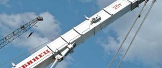
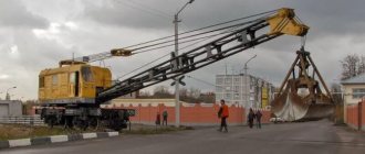
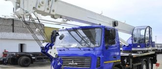
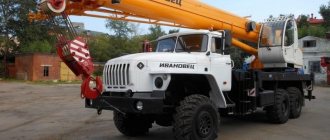
The KS-45721 family of crane installations, based on 3-axle commercial chassis KamAZ, MAZ or Ural, is designed to move cargo weighing up to 25 tons. The base chassis has all-wheel drive or only the rear bogie, respectively, a single-slope all-terrain or a double-slope highway is used busbar Serial production of modernized equipment under the Chelyabinets brand has been carried out since 2010.
Device and purpose
The crane is designed for loading and unloading operations, as well as during the construction of dispersed facilities. The basic version is intended for operation at temperatures from -40°C to +40°C. On request, taps can be manufactured in tropical or northern versions. The base chassis is equipped with a hydraulic rear bogie suspension lock, which is activated during lifting operations.
The machines are equipped with a telescopic boom consisting of 3 sections. Length adjustment is carried out using hydraulics and chain hoists. The installation angle is changed using 2 power hydraulic cylinders equipped with automatic locks. An axial piston pump is installed on the chassis transmission. The supply of working fluid is placed in a separate tank. The pumping station is connected to executive hydraulic motors.
To increase the stability of the machine, 4 outriggers are used, installed at the corners of the crane platform. The supports are equipped with a hydraulic drive and reinforced working cylinders.
The basic version of the KS-45721 automobile crane is equipped with control mechanisms using levers. Upon request, an improved control system for the crane installation is installed, which includes 2 joysticks. This control technique provides increased accuracy of boom movement and reduces fatigue for the crane operator. The operator's workplace is equipped with an ergonomic seat with a headrest and an adjustable waist support.
An electronic module is installed in the operator's cabin that limits the load capacity depending on the reach and angle of the boom.
The parameters are displayed on the liquid crystal display. The module contains a non-volatile storage device. Additionally, a block was used that prevents the crane from operating dangerously close to power lines.
The operator's workplace is located in a cabin with improved visibility. The design of the unit provides protection for the crane operator from noise, dust and precipitation. The basic equipment includes an auxiliary heater and a protective grille on the roof. The cabin is equipped with 2 headlights designed to illuminate the work area.
According to certain requirements, the KS-45721 truck crane is supplied with air conditioning and other modifications that ensure the operation of the equipment in hot climates. The vehicle is produced in a northern version, characterized by improved thermal insulation of the cabins and an additional pre-heater for the power plant.
General description of the truck crane
The drive of the crane installation is hydraulic from an axial piston hydraulic pump, driven from the power take-off.
The boom is 3-section telescopic, the sections are made of two metal structures of bent profile, which ensures a lower weight of the boom and increases the stability of the crane. Due to greater flexibility, the level of dynamic loading of the lower frame and outriggers is reduced, and stress is evenly distributed along the entire length of the boom. The base of the root section has been strengthened.
Winch with planetary gear: more compact and lighter, with a larger speed range and increased service life.
Multi-stage system for cleaning the fluid and cavity of the hydraulic system: hydraulic system filters allow you to reliably clean the working fluid and units from contaminants and small particles entering the system, making it easy to maintain.
Safety is ensured by a microprocessor-based load limiter, which protects against overload and tipping, damage when working in cramped conditions, and dangerous voltage in the power line area. The “black box” telemetric memory records the operating parameters and degree of load of the crane throughout its entire service life. Easy removal of information from the parameter recorder using a flash card.
Available upon request:
- A comfortable cabin with a large glass area and increased visibility. The thermally insulated operator's cabin has a modern ergonomic design with improved visibility to ensure operational safety, noise and waterproofing, and is equipped with an autonomous heating system.
- Production crane operator seat / “PILOT”, which has mechanical suspension with hydraulic shock absorption and pneumatic support for the back, headrest
- Armrests with built-in crane control joysticks. This layout ensures smooth, easy and precise control. Operator fatigue is reduced, safety and productivity are increased.
- To increase the lifting height of the hook and the size of the under-jib space, the crane is optionally equipped with a lightweight jib 7 m long, which has a unique patented membrane-type design and has high strength and rigidity.
- Satellite navigation system Real-time tracking of mobile vehicles, safety and optimization of the vehicle fleet, routing
- Security and search function - the ability to protect mobile vehicles from theft
- Insulation of chassis and crane operator cabins, battery compartments
Specifications
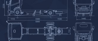
Technical characteristics of the crane mounted on the KamAZ-43118 all-wheel drive chassis:
- length - 10900 mm;
- width - 2500 mm;
- height - 3820 mm;
- total weight of the unit - 21600 kg;
- engine type - KamAZ 7403-10;
- power - 260 hp;
- compliance with environmental standards - Euro-3;
- speed on the highway is up to 60 km/h.
When using the KamAZ-53228 chassis with rear bogie wheel drive, the engine power is slightly increased and the overall height is reduced. Other characteristics remain unchanged. The Ural KS truck crane is distinguished by the use of a YaMZ-236NE2 diesel engine equipped with a turbocharger.
Load height characteristics
The KS-45721 Chelyabinets truck crane, mounted on a MAZ and KamAZ chassis, has the following parameters:
- load capacity - up to 25 tons;
- load moment - up to 80 t/m;
- lifting height (with standard boom) - 21.9 m;
- lifting height of the load when installing the jib - 29.1 m;
- boom radius (standard/jib) - 20/26 m;
- boom length adjustment range - 9.7-21.7 m;
- permissible depth of lowering the load - 17 m;
- speed of lifting load up/down - 5.0/7.0 m/min;
- crane tower rotation speed - up to 1 rpm.
When using the Ural chassis, the following characteristics change:
- speed of load movement up/down - 6.0/12.0 m/min;
- crane tower rotation speed - up to 2.2 rpm.
Make a request for a truck crane KS-45721-24
The information provided is for advertising purposes only. Specifications are subject to change without notice. Topic of the page: Mobile cranes Chelyabinets. Chelyabinets.rf Sale of KS-45721-24 truck cranes based on KAMAZ-43118 Chelyabinets (25 tons, 25 tons, 25 tons): cost, buy, price for a new KS-45721-24 truck crane. Description of the KS-45721-24 truck crane on the KamAZ-43118 chassis (25t, 25t, 25t): technical characteristics, load-height characteristics, device, diagram, diagram, dimensions (overall dimensions), features of the KS45721-24 crane on the KAMAZ43118 chassis. URAL truck crane, KAMAZ truck crane, MAZ truck crane. Automotive cranes Chelyabinsk. We are on Google+ Author: Google Copying site materials is prohibited. All rights are reserved by copyright law.
User manual
The Operation and Maintenance Manual provides for the following actions to be performed regularly:
- adjusting the cargo winch brake;
- checking the functionality of the winch holding mechanism;
- checking and adjusting axial clearances in bearings of lifting mechanisms;
- adjustment of the brake system of the crane tower rotation gearbox;
- adjusting the degree of tension of the boom sections drive ropes;
- checking and normalizing the length of drives used to control the operation of the crane;
- adjustment of the power plant speed control system from the operator’s cabin;
- setting up the load limiter, as well as other similar systems.
The safety of work depends on timely and accurate inspection of components. It is prohibited to operate the crane with disconnected or faulty limiting devices, as well as faulty brakes of the winches and slewing mechanism.
MANIPULATING CRANES, CMU UNITS, TRUCK CRANES
_____________________________________________________________________________________________
Adjustment and configuration of equipment for truck cranes KS-45721, KS-45715
Adjusting the brake of the cargo winch of the truck crane KS-45721, KS-45715 Adjusting the brake of the cargo winch must be done in the following sequence: - set the working length of the spring with nuts equal to 110±1 mm; — screw the bolt until the brake band stops in the pulley, and then unscrew it 0.5-1 turn and lock it; — set a distance of 12±1 mm between the bolt head and the rocker arm bridge. Adjustment should be made by moving the bolt and the hydraulic brake release. After adjustment, it is necessary to lock the bolt and hydraulic release with nuts; Check the reliability of holding the maximum load by the brake of the cargo winch of the KS-45721, KS-45715 truck crane in the following sequence: - raise the maximum permissible load to a height of 100-200 mm; — open the valve connecting the pressure and drain lines of the hydraulic motor. The brake should keep the load from going down. Check the marks marked with chalk on the pulley and brake band. Friction linings can be used until their thickness is reduced to half the original thickness (the initial thickness of the lining is 6 mm). If the lining wears unevenly, its thickness in the middle part should be at least 1/2, and in the outer part - at least 1/3 of the original thickness.
If the thickness of the lining is reduced to the dimensions specified above, as well as if it is worn down to the rivet heads, replace the lining and adjust the brake. Adjusting the gearbox of the truck crane lifting mechanism KS-45721, KS-45715 To adjust the axial clearance of the conical bearings of the gearbox of the truck crane lifting mechanism KS-45721, KS-45715, it is necessary to tighten the previously unscrewed adjusting screws until full, then, starting from the high-speed shaft, release them to 0. 5-1 pitch of holes on the ends of the adjusting screws and securely fasten with locks. Adjusting the installation of the pressure roller of the drum of the KS-45721, KS-45715 truck crane. Adjusting the installation of the pressure roller is necessary to ensure correct winding of the rope onto the drum and the possibility of unwinding it from the drum. The roller must be installed symmetrically relative to the drum flange using a set of shims. The difference in size should not exceed 2 mm. The working length of the spring, equal to 140+5 mm, must be installed with nuts. The spring length is set by winding the rope in three layers onto the drum. Adjusting the brake of the turning mechanism of the KS-45721, KS-45715 truck cranes Adjusting the brake of the turning mechanism of the KS-45721, KS-45715 truck cranes must be done in the following sequence: - set the working length of the spring with a nut equal to 88 ± 2 mm and lock with a second nut. To ensure uniform release of the brake pads and set the gaps between the adjusting bolts and the lever bars, it is necessary: - loosen the nuts of the adjusting bolts; — screw the bolts in until they stop, turn them out 2-3 turns and secure with nuts. As the friction linings wear, it is necessary to adjust the length of the spring and the size of the gaps. The friction linings of the brake of the turning mechanism of the truck crane KS-45721, KS-45715 can be used until their thickness is reduced to half the original thickness (the initial thickness of the lining is 6 mm). If the lining wears unevenly, its thickness in the middle part should be at least 1/2, and in the outer part - at least 1/3 of the original thickness. If the thickness of the lining is reduced to the dimensions specified above, as well as if it is worn down to the rivet heads, replace the lining and adjust the brake. After replacing the linings, the brake must be adjusted. Adjusting the tension of the ropes for extending (retracting) the sections of the telescopic boom of the KS-45721, KS-45715 truck crane. Adjusting the tension of the ropes for extending (retracting) the boom sections of the KS-45721, KS-45715 truck crane must be done when the boom sections are not synchronously extended or retracted (when extending the upper section " lags" in relation to the middle section; when retracted, it "lags behind" the middle section). Adjust the tension of the ropes in the boom of the KS-45721, KS-45715 truck cranes in the following sequence: - install the truck crane on extended outriggers; — raise the boom to a reach of 2.5-3 m and rotate it into the working area of the crane; — extend and then fully retract the boom sections; — lower the boom to a horizontal position. Lowering should be done smoothly, while preventing movement of the boom sections. There should be no gaps in the joints. If there are gaps, repeat the extension (retraction) of the boom sections; — use nuts to first loosen the tension of the rope for retracting the upper section of the boom of the KS-45721, KS-45715 truck crane; — use nuts evenly on both rods to tension the ropes 6 for extending the upper section until a gap appears at the joint within 1-2 mm. In this case, it is necessary to ensure a size of 30-50 mm; — use nuts to tension the rope 8 to retract the upper section until the gap in the joint is eliminated; - while holding the nuts from turning, securely lock them with locknuts. It is necessary to avoid over-tightening the ropes, as this can lead to vibration of the boom when retracting the sections. When repairing the boom of the KS-45721, KS-45715 truck crane, which entailed disconnecting the pipelines from the hydraulic cylinder for extending (retracting) the boom sections and separating its retractable sections from the boom, it is necessary when assembling the boom before connecting the pipelines to the hydraulic cylinder to perform preliminary adjustment of the tension of the extension ropes and retracting the boom sections in the following sequence: - retract the boom sections until they stop (until there are no gaps in the joints); — tighten the extension rope of the upper section of the boom with nuts until a gap appears at the joint within 1-2 mm. In this case, it is necessary to maintain a size of 30-50 mm; — tighten the retraction rope of the upper section with nuts until a gap appears at the joint within 1-2 mm; - tighten the nuts. Adjustment of the control drives for the actuators of the KS-45721, KS-45715 truck cranes. Adjustment of the control drives for the actuators of the KS-45721, KS-45715 truck cranes must be performed after adjusting the engine fuel supply control drive in the following sequence: - by changing the lengths of the rods (due to threaded connections) set vertical position of the handles. In this case, the handles must freely return from the working position to the neutral position under the action of the hydraulic distributor springs; - use screws to set a gap of 0.3-0.5 mm between the limit switch rollers and the screw heads at the selected free stroke of the handles. In this case, the switches should operate using no more than 1/3 of the travel of the switch rollers, and in the extreme position of the levers (away from you), the switch rollers should have a travel reserve of at least 1 mm; — tighten the locknuts on the screws; — set the rotation speed of the hydraulic pump of the truck crane KS-45721, KS-45715 to 1000-1200 rpm; — limit the stroke of the handle with bolts to a value at which the speed of extending the boom sections without a load and retracting the boom sections with a load of 0.6 tons on the hook will be no more than 18 m/min; - limit the stroke of the handle with bolts to a value at which the time of change in reach is from 5.5 to 19.7 m at a maximum lowering speed of a boom 21 m long with a load on the hook of 0.7 t and lifting without load will be 45-50 seconds. After installing the jib on the KS-45721, KS-45715 truck crane, it is necessary to: - limit the handle stroke with bolts to a value at which the maximum rotation speed of the turntable in both directions will be no more than 0.8 rpm; - limit the stroke of the handle with bolts to a value at which the maximum speed of raising and lowering the hook suspension without load will be no more than 35 m/min with a single reeving of the cargo rope. Adjusting the engine fuel supply control drive from the crane operator's cabin When the chassis engine is heated to a temperature of at least 75 °C and the temperature of the working fluid in the hydraulic system of the KS-45721, KS-45715 truck crane is not lower than 20 °C, it is necessary to adjust the backup engine fuel supply control drive from the crane operator's cabin in the following sequence: — check the operation of the control drive in the driver’s cabin. In case of unsatisfactory operation of the drive, adjust it in accordance with the instructions in the chassis manual; — stop the chassis engine; — at position I of the pedal (corresponds to the minimum crankshaft rotation speed at idle speed of the chassis engine), it is necessary: — by changing the length of the rod (using its threaded connections) to ensure the position of the lever in which it is deflected back from the vertical by an angle of 6°±2°; — loosen the bolt and move the clamp (together with the end of the spring) along the cable to ensure that the spring is stretched to a size of 430+10 mm. Tighten the bolt; — start the chassis engine; — set the pedal to position II (corresponds to the chassis engine crankshaft speed of 900-1100 rpm). If the specified revolutions are not achieved, ensure the required rotation speed by rearranging the rod in the holes of the lever. In this case, finer adjustments can be made using nuts; — set the pedal to position III and use the adjusting bolt to set the chassis engine crankshaft speed to 1270.50 rpm. The engine crankshaft revolutions should be measured using the tachometer in the driver's cabin. Adjusting the load limiter of the KS-45721, KS-45715 truck crane Install the KS-45721, KS-45715 truck crane on outriggers and check the horizontal hanging of the crane (the difference in overhang when the platform is rotated 90° should not exceed 50 mm when measured at three points at outreach 3 .5 m). Adjust the sensors and limiter after checking the connection of the plug connectors to the data processing unit and the load limiter sensors. When the boom sections are fully retracted, the normally closed contact of the limit switch must be open, and when the boom length increases beyond 9.01+0'1 m, it must be closed. Adjustment is carried out by moving the stop. Adjust the limiter on the KS-45721, KS-45715 truck cranes in accordance with the sections of the Instructions for installation, start-up and adjustment of the load limiter included in the set of crane operational documentation. When lifting nominal loads specified in the appendix at the corresponding boom lengths and outreaches, the limiter must allow the operation of the truck crane, and when lifting loads exceeding the nominal loads for the corresponding outreaches and boom lengths by more than 10%, prohibit the operation of the crane. The limiter must be checked quarterly in accordance with the load limiter section of the Operator's Manual. Adjusting the limiters for the lifting height, lowering depth and tilt of the boom of the KS-45721, KS-45715 truck crane. Adjusting the operation of the limit switch of the lifting height limiter must be done by changing the length of the cable supporting the load of the limiter.
The limiter must turn off the lifting mechanism at a distance of at least 0.2 m from the stop of the hook suspension to the head of the boom or jib. Adjustment of the operation of the boom tilt limiter of the KS-45721, KS-45715 truck cranes must be done with a boom length of 9 m at an outreach of 1.7 m by turning the eccentric stop and moving the bracket with the switch.
When pressing the switch roller with a stop, ensure that the roller moves 1-2 mm freely after the limiter is activated. The lowering depth limiter must operate when at least 1.5 turns of rope remain on the winch drum. Adjustment must be made by moving the nut along the axis of the screw as it rotates.
_____________________________________________________________________________________________
_____________________________________________________________________________________________
- Main equipment and parameters of Unic CMU
- Operation of the Unic crane installation
- Palfinger CMU design
- Palfinger manipulator overload protection system
- CMU Hiab 190
- Hiab XS 320 loader crane
- Hiab 100/120 hydraulic manipulator
- CMU Tadano
- CMU Amco Veba
- KMU Fassi
- CMU Dongyang SS1506
_____________________________________________________________________________________________
- Equipment KS-35714
- Hydraulic system KS-35714, KS-35715
- Equipment and mechanisms KS-3577-4
- Recommendations for repairing KS-3574
- Hydraulic equipment KS-55713
- Repair of telescopic boom KS-55713-1K-3
- Parts and mechanisms of the rotating part KS-45717-1
- Design and controls KS-4572, KS-45719
- Operation of hydraulic equipment KS-45721, KS-45715
- Device KS-55727
- Review of the KS-6476 design
- Maintenance of KS-3579
- Adjustments KS-35719
- Truck crane KS-3575
- Crane KS-5576 Ivanovets
- Truck crane KS-5473 Dnepr
- XCMG QY25K5S truck crane
- Crawler crane MKG-25 BR
- Repair of chassis DEK-251
- Crane RDK-250
