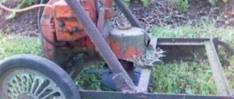
Large farms use all kinds of grinders to prepare feed mixtures based on grass crops. Typically, these grinders are very powerful and are designed to grind large quantities of feed. For a subsidiary farm where the livestock is small, the use of industrial grinders is not advisable. Of course, the industry also produces these small-capacity units, which are just suitable for preparing feed in small quantities. But their cost is sometimes very high, so many farm owners often make shredders with their own hands.
Advantages of do-it-yourself feed choppers
First, let's talk about what shredders are and what they are intended for. Grinders are mechanical devices designed to break feed into small particles, which are easier for young animals to absorb and less likely to stretch and trample.
Homemade shredders have a number of advantages. Firstly, many of the components are readily available, so the cost of manufacturing them will be low. Secondly, you can make choppers for preparing certain types of feed. Thirdly, having such a chopper, it is possible to prepare fresh feed every day, which ensures that it is more readily absorbed by young and adult animals.
As stated, you can make this device with your own hands for certain types of feed. Therefore, we will consider the simple designs of three choppers that process different feeds.
Grass chopper
First, let's look at making a grass chopper to feed calves or nettles to feed chickens. Such a unit will be required for those who have poultry and young animals of small and large horned livestock, pigs on their farm.
Since we are talking about mechanical devices, it should be noted that this design includes a mover. Electric motors are most often used, since they are more convenient to use, and the chopper itself will be stationary.
The materials you will need are: an electric motor with a speed of approximately 3000 rpm (such speeds are needed for finer cutting of the grass), a base, a working container, chopping knives, and tin for making a discharge sleeve.
The tools you will need are a welding machine, a grinder, a drill with metal drills, a set of keys, connecting elements (bolts, nuts, rivets).
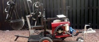
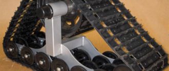
Photo of a homemade herb chopper
The described chopper has a vertical design. All elements are attached to a base consisting of a square metal plate 4-5 mm thick. The legs are welded to this plate at the corners. The height of the legs should be selected according to the length of the electric motor, which will be located between the legs. In this case, the lower part of the engine should be located at a height of 15-20 cm from the ground. A hole is drilled in the center of the plate to output the electric motor shaft.
On the other side of the legs, a working container is attached to the base. This can be an old saucepan of significant volume, or you can use any other container, as long as it is cylindrical. You can attach it to the base with bolts, you just need to make the markings correctly and drill the holes. A rectangular hole is cut in the lower part of the container to drain the crushed food. A box is formed from the prepared tin, which must be attached to the container on the cut hole. It can be attached with rivets.
The electric motor can be used from an old water pump, as long as it is in good working order. The water impeller housing is removed or cut off, leaving only the engine itself. You can attach it to the base with two metal strips and a bolt connection.
Knives can be made from an old wood saw blade. Two strips 5 cm wide are cut and the length is selected according to the diameter of the container (the knives should not reach the walls of the container by about 5 cm). Holes are made in the center of the strips. The edges of the knives are sharpened. The knives are installed on their axis in a cross.
To secure the knives to the electric motor shaft, you will need to make a special adapter, which, on one side, fits onto the shaft and is secured to it; on the other hand, the knives will be placed on the adapter. On this side you will need to cut a thread to firmly fix the knives with a nut.
Arrangement of knives in the grass chopper
After assembling all the elements into one structure, you can install a metal strip inside the container, which must be secured perpendicular to the inner surface of the container. It is important that this strip does not reach the knives. The purpose of this tape will be to prevent grass from wrapping around the knives.
After assembly, you will need to check the reliability of all connections, after which you can carry out a test run. Even when grinding feed, it is better to cover the container with some kind of lid to prevent grass from flying out of the container.
Classification of livestock feed dispensers
Among feed dispensing machines, there are the following classification differences regarding functionality and design:
By type of chassis:
- Self-propelled
- Trailed
By functionality:
- Feed dispensing machines
- Dispensers - mixers
- Mixer dispensers with simultaneous mixing and grinding functions
In addition, the machines can be equipped with loading equipment
By design, distributors are divided into:
- Conveyor systems, where the movement of the mass of feed from the bunker is carried out using built-in conveyors. Such machines work with the distribution of prepared crushed and pre-mixed feed.
- Horizontal auger – mixing and grinding is carried out by horizontally placed augers in the dispenser hopper.
- Vertical screw, where dispensing machines combine the functions of a mixer and a distributor. Direct supply of the feed mixture to the feeding table or feeders is carried out by spilling through unloading windows or using additional belt conveyors.
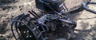
Juicy feed chopper
For those keeping pigs and cattle on their farm, it would be a good idea to have a succulent feed chopper. It will be needed for grinding root vegetables for further preparation of feed consisting of several ingredients.
There are several design options for succulent feed choppers, but we will not consider them all. Let's consider a version of a chopper that is structurally similar to the one described, that is, vertical.
Drawing of a vertical succulent feed chopper
1 - hopper, 2 - damper in open position, 3 - exit window, 4 - bumper belt, 5 - cutting device, 6 - start button, 7 - electric motor, 8 - tripod.
You will need material for the base, an electric motor, a cylindrical container, material for making a knife and a box for discharging crushed feed. The tools used are those described above.
The design is the same: a base with an electric motor attached to the bottom and a container on top. A shaft is inserted inside the container, onto which the cutting element is attached.
But there are several features. So, for a succulent feed chopper you will need to find a traction motor with not very high speeds. Traction, because chopping root vegetables requires good force. And not a high-speed one, because significant speeds will crush root vegetables to the point of porridge.
The container should have a wall thickness of 2-3 mm, since its walls will experience shock loads.
There is only one knife used on such a chopper and a saw blade is not suitable for its manufacture; it is better to use a metal strip 3-4 mm thick.
There is no need to install a strip of metal inside the container. Be sure to have a lid on the container.
Feed dispenser KTU
This machine is a development of the Soviet agro-industrial complex based on the chassis of a two-axle tractor trailer 2 PTS-4. The work of the distributor is to supply the prepared crushed feed from the body with a chain longitudinal conveyor and transverse beaters onto a transverse belt conveyor to the side windows of the body, where the mass falls onto a height-adjustable small unloading additional conveyor.
KTU-10
Operation of KTU-10
Depending on the modification of the dispenser, feed can be unloaded on either one or both sides. The machine is driven as standard from the power shaft of the tractor being coupled.
KTU-10 distributor device
| Load capacity, kg | 4000 |
| Body volume, m³ | 10 |
| Weight, kg | 2100 |
| Transport speed, km/h | Up to 35 |
| Operating speed, km/h | 2 |
| PTO drive rotation speed, rpm | 540 |
| Dimensions, m length width height | 6670 2300 2500 |
| Track width, mm | 1600 |
| Distance between the outer sides of the wheels, mm | 1860 |
| Ground clearance without load, mm | 320 |
| Service brakes | Pneumatic with single-line drive |
| Parking brake | Mechanical with manual drive |
An analogue of this distributor with similar technical characteristics is the KRF-10 machine.
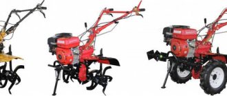
Cereal grinder
Animals are often fed grain-based feeds. Moreover, grain-based feeds are used to feed poultry, young livestock and adult livestock. For better digestibility of grains, it is better to grind them before feeding, since whole grains are often not digestible by animals and birds. To prepare grain-based feeds, they are first crushed using a chopper. You can also make such a chopper yourself, but it is more difficult to make.
All grain grinders have a horizontal position. To make it you will need an electric motor, sheets of tin, a metal sieve, connecting elements, two square metal sheets with sides of 10 cm and a thickness of 3 mm, a square sheet with sides of 50 cm and a thickness of 4-5 mm, material for making knives.
So, such a chopper requires a high-speed electric motor, which ensures fast and high-quality crushing of grains.
Having the necessary material at hand, you will need to make working and feeding hoppers, as well as a hammer drum. Let's start with the working bunker.
Work hopper
To make it you will need a square sheet with sides of 50 cm and sheets of tin. On a square sheet you need to mark the output of the electric motor shaft; it should be located exactly in the middle. This sheet will be the back wall of the bunker. It will be attached to the electric motor.
Next you will have to work with tin. To begin with, an even strip 10 cm wide is cut out. Its length should be such that, having rolled the strip into a ring, its circumference does not protrude beyond the edges of the back wall. The edges of this ring will need to be welded together.
The existing ring made of a tin strip is applied to a sheet of iron and markings are made. Moreover, the edge of the marking should protrude beyond the ring by about 10 mm.
Next, a circle is cut out according to the markings. The 10 mm edge made during marking will need to be bent to one side by 90 degrees. To make bending easier, you can make slits at certain intervals. The task is to make sure that the ring fits tightly into the curved edges of the cut out tin circle. Having placed the ring on the circle, they will need to be connected to each other using a welding machine, and they need to be welded so that there are no gaps.
The resulting structure will be the front wall of the working hopper. Then markings are made on the back wall, ensuring that the manufactured front wall is positioned strictly in the center.
The next task is to make a supply and discharge window in the front wall of the bunker. To do this, you need to make two cutouts across the entire width in the made ring of tin. One is 20 cm long; this will be a discharge window. You will need to attach a metal sieve to the place of the cut piece. Regarding the sieve, it should be noted that the smaller its cells, the more the grain will be crushed. You can secure the sieve strip with rivets. Opposite the outlet window, a supply window 5-7 cm long is cut out.
Hammer drum
The grain is crushed using a hammer drum. It is made from two squares with sides of 15 cm. Their arrangement to each other is parallel. A hole is cut in the center of one of the plates for the electric motor shaft. There must be a certain distance between the plates, and they are rigidly fixed to each other.
A rigid fastening is made by drilling holes in the corners of the plates. Long bolts are inserted into these holes. After inserting the bolt, it will need to be pressed against the plate with a nut. Next, crushing knives are placed on the bolt, made in the form of plates 7 cm long and 3 cm wide, and sharpened on both sides. The length of the knives may vary; it is important to ensure that it does not touch the walls of the hopper.
On one side of the knives, a hole is drilled, the diameter is slightly larger than the diameter of the plate coupling bolt. Having secured the bolt to the plate, a knife is put on it, then a washer is put on the bolt, then another knife. The number of knives can be increased, but it is important that the drum does not rest against its wall when assembling the working hopper. Then another nut is screwed onto the bolt, but so that it does not tighten the knives and does not prevent them from moving freely around the bolt. This nut will be the fixing nut for the second plate.
The knives are installed on all 4 corners of the plate with bolts. Then a second plate is put on the 4 bolts with the knives installed and clamped with nuts. The nut installed before this will prevent the knives from being tightened in the future.
Then you need to check whether the knives rotate freely and whether they will cling to the walls of the working hopper. After this, the drum is placed on the shaft. You may need to use an adapter to secure it. After installing the drum on the back wall of the hopper, it is connected to the front. To avoid gaps, you can place a thin rubber spacer between them. The two halves of the hopper are compressed together with 4 pins, for which you need to drill holes in the two walls at the maximum possible distance from the center. After connecting the two halves of the working hopper, you need to check whether the mounting pins will catch on the knives. Drawing of hammer drum assembly
Feed hopper
All that remains is to make the supply hopper. It is made of tin in the form of a pyramid with a truncated top. The area of the top must correspond to the dimensions of the feed window of the working hopper. Closer to the top, a slot is made in one of the walls, and another one is made parallel to it. A plate is installed in these slots, acting as a valve, with the help of which the flow of grain into the working hopper will be regulated.
Feed hopper drawing
The feed hopper is fixed to the window of the working hopper by welding.
After assembly, you will need to check all connections, after which you can perform a test run. If a strong roar is heard, it means the knives are clinging to something and you may have to shorten them. The video shows the process of making a grain grinder with your own hands:
Feed mixers AKM
Feed dispensing machines are manufactured by the Russian JSC Slobodskoy Machine-Building Plant. The design is a grinder-mixer with a vertical auger. Today the plant presents trailed mixer-distributors in two models: AKM-9 (single-screw) and AKM-14 (double-screw).
Mixer dispenser AKM-9
The dispensing machines are equipped with a weighing system that allows optimizing the preparation of feed mixtures. The functionality and quality of the machines are not inferior to foreign analogues, which allows the manufacturing company to successfully compete in the Russian agricultural machinery market.
Technical characteristics of AKM-14
| Hopper volume, m³ | 12 |
| Drive from PTO, rpm | 540 |
| Number of screws | 2 |
| Maximum loading weight, kg | 4500 |
| Feed distribution | By conveyor belt on the left or right side in the direction of travel |
| Distribution unevenness, % | 9-13 |
| Unloading height, mm | 600 |
| Distance between the outer sides of the wheels, mm | 2065 |
| Wheel size | 315/80R22.5 |
| Dimensions (length/width/height), mm | 5929/2300/2660 |
| Weight, kg | 4300 |
| Transport speed, km/h | Up to 12 |
| Operating speed, km/h | 0,5-2,5 |