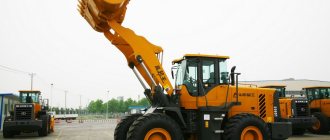
Single-bucket front loaders can perform the following operations:
- movement to the place of work and throughout the work area,
- lowering and raising the boom structure with a bucket,
- introduction with the pressure force of the bucket into the material and loading,
- transportation of bulk materials and cargo in a bucket,
- unloading the bucket by tipping.
This set of functions allows such machines to be widely used in various areas of construction, land reclamation, and unloading and loading operations.
In general, the working equipment of single-bucket front loaders is a boom structure, the axis of which is fixed to the machine frame (the front part of the loader). The middle part of the boom rests on hydraulic cylinder rods, which are responsible for raising and lowering the structure.
In order to increase the efficiency and productivity of machines, it is necessary to select attachments in accordance with the tasks performed.
- Standard models of buckets with a straight cutting edge are used for handling bulk materials with a bulk density of 1.4...1.8 t/cub.m. (clayey soils, gravel, sand). These same buckets can be equipped with a double-sided cutting edge, which has increased strength and wear resistance. The replacement edge can be either solid or made of segments.
- High-capacity buckets are capable of loading 1.5-2.5 times more. They are used for handling fairly light materials: household waste, peat, wood chips, snow, etc.
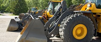
- Heavy-duty buckets come in a variety of designs. They can have a straight or triangular cutting edge, and attachments can be equipped with teeth. Such buckets are used for handling large-sized and dense materials, including stone.
Equipping various types of buckets with lattice canopies allows the operator to maintain good visibility and fully control the work process.
If necessary, the loader bucket can be replaced with other attachments.
Classification of single-bucket front loaders
In most cases, loaders are machines designed based on tractors. Thus, depending on the type of chassis of the base vehicle, units can be divided into tracked and wheeled. Single-bucket wheeled front loaders are created on the basis of self-propelled chassis and serial wheeled tractors.
Pneumatic wheel models are characterized by the ability to work effectively in cramped conditions due to good maneuverability. In addition, such machines have a high speed (for this type of equipment) - up to 40-45 km/h. This allows them to be used at facilities with dispersed points of action, for example, at cargo processing points.
Crawler, respectively, based on various models of tractors with the corresponding method of movement of serial production. Front-end single-bucket loaders can have different types of lever systems: Z-shaped kinematic scheme, parallelogram or mixed type system.
The rotary design of the loader can be implemented as control of all wheels or an articulated frame. In addition, skid steer vehicles are available.
On machines of this type, a mechanical, hydrostatic or hydromechanical transmission is installed, which is used in most cases. The most efficient are machines with forward unloading. Lateral unloading on them is carried out using additionally installed hydraulic cylinders. Semi-rotary machines carry out unloading, including in both directions from the front direction at an angle of up to 90?. Combined machines were designed as universal equipment. They are able to unload backwards, carrying the bucket over themselves. This technique is not widely used due to its overly complex design, which significantly increases the cost of the loader and complicates repairs in the event of failure.
Rice. 4.1. Single-bucket loaders: a - with a rotating boom; b - with lateral unloading; c, d - frontal with front unloading; d, f - about rear unloading
Rice. 4.2. Single-bucket front loader TO-18 with various types of working equipment: a - with a bucket; b - with a rotary auger snow blower; in "- with thermal equipment for clearing airfields of ice
Table 4.1 Technical characteristics of single-bucket construction loaders (according to GOST 12568-67)
The presence of replaceable equipment makes front loaders universal.
The main parameter of single-bucket loaders is lifting capacity. GOST 12568-67 defines the standard range of construction single-bucket loaders with a lifting capacity of 2, 3, 4, 6 and 10 tons, and according to the nominal capacity of a normal bucket, 1, respectively; 1.5; 2; 3 and 5 m3 (Table 4.1). The main working part of the loader is a normal bucket, used for developing soils of category I-II and loading bulk small-sized materials with a volumetric mass of up to 1.6 t/m3.
Wheeled single-bucket loaders are more maneuverable and mobile compared to tracked ones, and tracked ones are more passable off-road. According to their structural layout, wheel loaders can have swivel wheels and an articulated turning device.
Rice. 4.3. Single-bucket front loader TO-6: 1 - bucket; 2 — rotation lever: 3 — boom; 4 — bucket rotation cylinder; 5 — boom lift cylinder; 6 — cabin; 7 - engine; 8 — rear driving steered wheels^ 9 — frame; 10 - portal; /U.-* front driving unsteered wheels; 12 — bucket turning rod
In Fig. 4.3 shows the layout of the TO-6 loader with two drive axles and rear steered wheels. The front axle with the driving non-steerable wheels is rigidly attached using stepladders attached to the frame brackets. The rear axle with driven steering wheels is suspended from the frame on a rigid transverse balancer, which relieves the frame from torsional deformations and transmits pushing forces well. The working equipment consists of a bucket, lever and hydraulic drive systems for the working equipment. The lever system has levers for turning the bucket, 3 booms and rods. The upper end of the booms is hingedly attached to the portal, and the bucket is hingedly attached to the lower end of the booms. Raising and lowering of the boom together with the working element is carried out by lifting hydraulic cylinders, and rotation of the working element is carried out by turning hydraulic cylinders.
The loader has a diesel engine located at the rear of the machine. The engine is equipped with an NSh-32 hydraulic pump to drive the power steering mechanism and a compressor to drive the brakes and windshield wiper. The diesel power system includes a fuel tank, coarse and fine fuel filters, a fuel pump with a regulator, injectors, an air cleaner with an air intake pipe, and a starting engine fuel tank. The diesel lubrication system includes an oil pump with a receiver, coarse and fine oil filters and a radiator. The oil cooler is installed in the rear of the car behind the torque converter radiator and, together with it, is mounted on brackets to the water radiator. The diesel cooling system consists of a fan water pump and a radiator.
Rice. 4.4. Kinematic diagram of the TO-6 front loader 1 - engine; 2 — power take-off gearbox; 3 — hydraulic pumps NSh-46; 4 — hydromechanical gearbox; 5 — torque converter; 6 — gear shift reducer; 4 — transfer cases; 5 — front drive axle; 6 — rear drive axle with steered wheels; 7 — cardan shafts; 8 - gear pumps
The diesel engine is started by the PD-10M-2 starting engine. The transmission of rotation from the starting Engine to the diesel engine is carried out by a single-stage gearbox with a shutdown mechanism and an overrunning clutch. The gearbox switching device is installed on the power take-off gearbox, the switching handle is located on its right side. To ensure starting at low temperatures, the engine is equipped with an electric torch-type pre-heater.
The transmission (Fig. 4.4) of the loader consists of a power take-off gearbox, a hydromechanical gearbox, a cardan drive and drive axles. Power take-off gearbox 2 is designed for independent power take-off from the engine / to drive hydraulic pumps of working equipment. A device for switching on the starting motor is installed on the power take-off gearbox. The power take-off gearbox is bolted to the engine flywheel housing. The hydromechanical transmission (HMCT) is designed to convert and transmit torque from the engine to the drive wheels of the loader. It consists of two converters - hydraulic and mechanical. Hydraulic converter - torque converter automatically adjusts the speed of the loader depending on the resistance on the drive wheels or the cutting edge of the working body. The mechanical part of the GMKP consists of three gearboxes: the main gearbox with mechanical range switching and two power take-offs on the drive axles of the loader. Shifting forward and reverse gears within each range of the main gearbox is carried out by hydraulic friction clutches.
The torque converter, main gearbox and power take-offs, together with the main units of the GMKP, are combined into one unit mounted on the frame on three quick-release rubber supports. The torque converter is a single-stage, complex translucent, has pump and turbine wheels and two reactor wheels mounted on roller-type freewheels. The main gearbox is a dual-range four-speed gearbox with two gears in reverse. Switching from one range to another is carried out using a gear coupling located on the output shaft. Gear shifting within each range is carried out without releasing the gas, which is achieved using three multi-disc friction clutches installed on the primary shaft of the gearbox. Power take-offs for the front and rear axles are designed to convert and transmit torque through cardan shafts to the loader axles.
The gearbox hydraulic system (Fig. 4.5) regulates the supply of working fluid (oil) to the torque converter and clutches, turns gears on and off, provides lubrication of bearings, gears of friction clutch disks and other rubbing surfaces, removes heat from gearbox parts, as well as cleans and cools the oil . The hydraulic system includes an oil tank, supply and discharge pumps, a pressure regulator, a pressure valve, a spool flow distributor (for reversing, gear changes and forced neutral), filters, an oil cooler and connecting pipelines.
All elements of the hydraulic system are installed on the GMKP, except for the tank, filters and radiator. The reverse, gear and forced neutral spools are assembled in one spool valve housing. The pressure regulator, pressure valve and spool valve are attached to the main gearbox body through a special adapter plate. The suction pipe of the feed pump is connected to an oil tank. The suction pipe of the bilge pump is connected to the transmission pan. The oil tank is mounted on the left wing of the loader.
The pressure regulator is designed to separate the oil flow in the main line and maintain a given pressure in it, as well as to protect the clutch and feed pump from damage due to a sharp increase in pressure. The sub-pressure valve is designed to regulate the hydraulic make-up pressure. torque converter, as well as to protect the torque converter and oil cooler from damage during a sharp increase in pressure in the torque converter feed line. The pressure valve is installed on the gearbox adapter plate next to the pressure regulator and is designed for a pressure of 1.5-2.5 kgf/cm.
Rice. 4.5. Diagram of the hydraulic system of the hydromechanical gearbox: 1 - drain line to the GMCP; 17 - 1st-3rd gear line; /// - 2nd-4th gear line; IV - reverse highway; / — pump-out pump NSh-32; 2 — feed pump NSh-32; 3 - pressure regulator; 4 - pressure valve; 5 — torque converter pressure gauge; 6 — torque converter thermometer; 7 - adapter plate; 8 - spool valve; 9 — cooling radiator; 10 — GMKP pressure gauge; // — hydraulic system tank; 12 — main filter; 13 — primary shaft of GMKP; 14.— pallet; 15 — torque converter (a — turbine wheel; b — pump wheel; c — reactor wheels); 16 — power take-off gearbox
Rice. 4.6. Diagram of the hydraulic system of the working equipment and steering mechanism: 1 - distributor for controlling the working equipment (c - pipelines and cylinders of the double-jaw bucket; b - to the boom lift cylinders; c - to the bucket rotation cylinders); 2 — hydraulic pumps of working equipment; 3 — hydraulic steering pump; 4 - hydraulic systems; 5 — tank filter; 6 - safety valve; 7 — hydraulic booster spool; £ t* power steering housing; 9 — power steering rod
The cardan drive of the loader consists of three cardan shafts: two short (from the power take-off gearbox to the gearbox and to the front axle) and one long (to the rear axle). The front axle consists of a beam, a gearbox, support axles, hubs with hub gearboxes, axle shafts and a cover. The rear axle consists of a gearbox, steering knuckles, support axles, hub gearboxes and axle shafts. The frame is welded, made of two longitudinal beams of a box profile.
The loader is equipped with power steering (Fig. 4.6). The steering wheel is connected to spool 7 of the hydraulic booster through a conventional worm steering mechanism, bipod and rod. The hydraulic booster rod 9 is fixedly mounted on the loader frame, and the steered wheels are connected to the hydraulic booster housing 8 through the steering drive. Thus, when the position of the distributor spool changes, its body moves, which turns the wheels. The hydraulic booster not only turns, but also perceives and absorbs shocks and shocks from the interaction of the driven wheels with the road, without transmitting them to the steering wheel. The hydraulic booster is driven by a gear pump mounted on the engine.
Rice. 4.7. Arrangement of articulated semi-frames and installation of axles on the TO-18 loader: 1 - front axle; 2 - koleoo; 3 — front half frame; 4 - hinge; 5 — balancing frame; 6 — rear axle; 7 — rear semi-frame; 8 — balancer hinge; 9 - bufevya; 10 - bolt
The hydraulic system of the working equipment supplies power to the drive cylinders of the working equipment depending on the position of the distributor control levers. The hydraulic system consists of an oil tank, supply gear pumps, a distributor, lift cylinders, rotation cylinders, filter 5 and connecting oil lines. Feed pumps NSh-46 are located on the power take-off gearbox, both pumps are of left rotation. The distributor is located in the cabin on the right side of the driver's seat. It consists of a pressure section, two working sections and a drain section.
In Fig. 4.7 shows the TO-18 loader with two driving fixed axles with an articulated frame and the U35605-3 hydromechanical transmission described above. The power plant consists of an A-OSH diesel engine and a power take-off gearbox mounted on the engine. The loader has two semi-frames - front and rear. Working equipment, similar to that of the TO-6 loader, is located on the front half-frame 3, and the engine and cabin are on the rear half-frame. The transmission and rear axles are driven, fixed, unified (U221003).
Rice. 4.8. Semi-frames of the TO-18 loader: 1 - front semi-frame; 2 - upper hinge; 3 — rear semi-frame; 4 - lower hinge
Some parts and components of the main drive and differential of the U221003 bridge and the rear axle of the MAZ-500 are interchangeable. The differential is a simple bevel, with four satellites, mounted on two tapered bearings, which also support the driven gear of the main gear. The differential box is detachable and consists of two cups. The differential is lubricated by oil coming from the axle housing through holes in the cups.
The gearbox is planetary, single-stage, with a fixed ring gear and three eatellites. The gears of the gearbox are made of alloy steel and have high surface hardness. The gearbox is lubricated with oil poured into the cavity of the gearbox. The wheel hub is a shaped steel casting mounted on two tapered roller bearings, one of which is located directly on the axle housing, and the other on the adapter hub of the wheel gearbox. The balanced type axle shaft is a shaft with splined ends, made of high-alloy steel.
The front axle is mounted on two pins and bolted to the front frame. The rear axle suspension ensures that it swings together with the balance frame in a vertical plane, which allows the rear semi-frame to be unloaded from lateral loads. The balance frame is bolted to the rear axle. To limit the angle of rotation of the frame and reduce dynamic shocks at the end of the turn, shock-absorbing rubber buffers are installed on it.
Rice. 4.9. Hinges connecting the frames: a - upper hinge; b - lower hinge; 1 - spherical bearing; 2 - thrust bearing; 3, 9 - fingers; 4, 6 - nuts; 5, 11 — bushings; 7 - cover; 8—adjusting shims; 10 — washer; 12 — oil seal; 13 - oiler
The hinged connection of the front and rear semi-frames (Fig. 4.8) is made using two coaxially located hinges: upper and lower. Radial loads are transmitted by articulated bearings (Fig. 4.9). The use of spherical bearings makes it possible to compensate for some inaccuracy in the manufacture of welded semi-frame structures. Vertical (axial) loads are absorbed by the thrust bearings of the upper hinge. The upper thrust bearing is installed on the pivot pin, the lower bearing is installed on the pin bushing. The tightening of the bearings is adjusted with a nut and shims. In the lower hinge, the tightening of the pin is adjusted by tightening the washer and bushing.
Loader wheels are split type. Tires size 16.00-24 twelve-ply, all-terrain.
The steering of the loader is hydraulic with servo feedback; it consists of a steering mechanism and an actuator - hydraulic cylinders that rotate one semi-frame of the loader relative to the other. The hydraulic steering system includes supply pumps - the main gear pump and the emergency axial plunger pump, an oil tank, a unified main filter, a check valve, pipelines and hoses.
The steering mechanism consists of a master, distribution and matching devices. The driving device is made in the form of a steering shaft-nut mounted on bearings. The switchgear is a housing in which a worm-spool moves when the steering wheel is turned. The matching device consists of an axial piston hydraulic motor and a differential gearbox. The hydraulic steering mechanism works as follows: the working fluid from the tank is supplied by a pump to the distribution device, the spool of which can be in three positions: neutral - the machine makes a straight movement, upper - right turn, lower - left turn. Then the working fluid enters the hydraulic motor and drives it.
Rice. 4.10. Pneumatic system of the TO-18 loader: 1 - brake chamber; 2 - pressure regulator; 3 - compressor; 4 - safety valve; 5 — receivers; 6 — valve for draining condensate and extracting air; 7 — condensate drain drain; 8 — signal switch; 9 — sound signal; 10 — windshield wipers (gel; U — windshield wiper activation valve; 12 — control pressure gauge; 13 — brake valve
The loader has a pneumatic system (Fig. 4.10), which provides power to the brake chambers, windshield wipers and sound signal. The loader has two shoe brake systems. The foot pneumatic brake is designed to brake a moving loader, the hand brake has a mechanical drive and is designed to slow down the loader when parked and for a short time in case of emergency failure of the foot brakes. The foot brake consists of four wheel brakes, a pneumatic drive, and a brake valve control drive. Two brake pedals installed in the driver's cabin through a rod system act on the brake valve of the pneumatic drive. The pedals are installed on a common axis and connected to each other in such a way that when you press the right pedal, the left pedal remains stationary, and when you press the left, both pedals are activated. The left pedal is connected through a linkage to the GMKP release valve, the right pedal is connected through a linkage to the brake valve.
To return the pedals to their original position, release springs are provided.
Rice. 4.11. Electrical equipment of the TO-18S loader 1 - headlight; 2 — connecting panels; 3 - turn relay; 4 -. lamp socket; 5 — brake light switch; 6 — temperature indicator; 7 — warning lamp lantern} 8 — ceiling light; 9 - switch; 10 —..temperature sensor; 11— portable lamp 12—socket; 13 — engine compartment lamp; 14 — relay-regulator; 15 - generator; 16 — rear right lamp; 17 — rear left lamp; 18 — heater; 19 - including (gel; 20 - battery; 21 - starter; 22 - heater; 23 - ammeter 24 - fuel level indicator; 25 - temperature indicator; 26 - fan; 27 - front left lamp; 28 - fuel level sensor; 29 — front right lamp
The wheel brakes are drum brakes, with internal expansion pads. The brake linings are made of asbestos mass and are attached to the rim with hollow brass rivets. The handbrake is mounted on a gearbox attached to the left side of the gearbox housing.
Compressor 3, installed on the loader, is a two-cylinder piston, located on the right side of the engine on a bracket attached to the rear frame. The compressor is driven by a V-belt drive from an additional pulley mounted on the engine crankshaft. The brake valve of the loader is interchangeable with the brake valves of ZIL-130 and MAZ-503A vehicles. The safety valve protects the pneumatic system from increasing pressure in the event of a malfunction of the pressure regulator. The valve is installed on the receiver and adjusted to a pressure of 9-9.5 kgf/cm.
The electrical equipment of the loader (Fig. 4.11) is intended for electric starting of the starting engine, illumination of the road and work area, working parts, cabin and instrument panel at night, as well as for driving a fan, cabin heater, pre-heater. Electrical equipment is connected via a single-wire system, in which the negative wire is the ground of the machine. The relay-regulator is used to automatically maintain the voltage at the generator terminals within the specified limits necessary to ensure normal operation of current consumers and compliance with the charging mode of the battery, to automatically turn on the generator in the circuit and protect it from overloads.
Rice. 4.12. Hydraulic system of the TO-18 loader: 1, 2, 4 - hydraulic cylinders; 3, 6 — retarding valves; 5 — hydraulic steering mechanism; 7—hydraulic distributor; 8 - pressure gauge; 9, 10, 12 - pumps; 7, 3, 21 — main filters; 14, 16, 17 — filler necks; 15 - drain valve; 18, 19, 20 — tanks; 22 oil radiator; 23 »» gear shift
The hydraulic system (Fig. 4.12) serves to drive the mechanisms and working parts of the loader, as well as to control their movement when performing work operations. The hydraulic system consists of an oil tank, feed pumps 9, 10 and 12, a distributor 7, two hydraulic cylinders / bucket rotation, two boom lift hydraulic cylinders 2, retarding valves 3 (screwed into the lower holes of the cylinders 2), main filters and the lines themselves. The P25.160 five-section distributor, with three working, pressure and drain sections, is mounted under the cabin floor and serves to direct the flow of working fluid into the actuating hydraulic cylinders. The pressure section is designed to supply fluid to the working sections and protect the pressure line from overload using a built-in safety valve. A cone check valve is also built into the pressure section, which serves to prevent the backflow of working fluid from the cylinder into the pump line and its leakage from the cylinder into the overflow channels when the spool is turned on and off.
The spool valves of the working sections are designed to control the cylinders and movement of one or another part of the working equipment. They can occupy three positions: one neutral and two workers. When the spool is in the neutral position, the working outlets are locked, the flow of working fluid from the pressure section through the overflow channel through the drain section goes into the tank. When the spool moves to the working position, the pressure line is connected to one of the working outlets, and the flow is directed into one of the cavities of the hydraulic cylinder. The grooves on the spool and the channels in the body of the working section are made in such a way that at the beginning of the overlap of the overflow channel, the liquid simultaneously flows to the hydraulic cylinder and into the drain line. This makes it possible to regulate the speed of the cylinder rod.
The spools of the working sections are moved to working positions and held in them manually, and return to the neutral position under the action of a spring.
The drain section is a hollow chamber into which all the drain and overflow channels of the previous sections exit, and has one threaded outlet for connecting the distributor to the drain line.
The axial plunger working equipment pump 210.25 is used to supply working fluid to the distributor and from it to the hydraulic cylinders. The pump is installed on the power take-off gearbox.
Unified single main-line sediment-type filters are used as drain filters in the hydraulic system. The loader is equipped with filters of two sizes: with a capacity of 100 l/min and a filtration fineness of 25 microns (in steering systems and hydromechanical gearboxes); productivity 160 l/min and filtration fineness 40 microns (in the working equipment system). To protect the filter elements from overloads, a safety valve is installed in the filter cover, adjusted to a pressure drop from 3.5 to 0.5 kgf/cm2.
The loader uses double-acting hydraulic cylinders. Cylinders with a diameter of 125 mm and a stroke of 710 mm at boom lift and 400 mm at bucket turns are installed on the working equipment. The cylinders are designed for a working pressure of 160 kgf/cm2. The steering system uses cylinders with a diameter of 80 mm and a stroke of 320 mm as an executive element.
Rice. 4.13. Single-bucket front-end loader TO-7 on a caterpillar tractor DT-75B-S2: 1 - counterweight; 2 - tractor; 3 - support; 4 - portal; 5—hydraulic boom lift cylinder; 6 — sleeve; hydraulic systems; 7 - hydrocilid] rotation of the bucket; 8 — bucket rotation lever; 9 - boom
Check valve G51-24 is installed in the steering hydraulic system. When machine G moves with the engine running, the flow of working fluid from the main pump, overcoming the force of the spring, lifts the valve and opens the passage from the pump to the steering mechanism. When towing a car, only the emergency pump operates, and the flow of working fluid from it presses the check valve to the seat, blocking the path of fluid to the main pump. Thus, the check valve allows fluid to flow in only one direction and prevents leakage through the stopped main pump.
Retarding valves are used to prevent the free fall of the working body with a load when lowering; They are installed at the outlet of the piston cavity of the boom lift cylinders. The valve is a movable washer with a central throttling and peripheral holes, the total area of which is equal to the cross-sectional area of the pipelines. When the boom is raised, all holes are open. When the boom is lowered, the liquid displaced from the piston cavity of the lift cylinder moves the washer all the way, and all peripheral holes are closed. The liquid passes through the throttling hole and slows down the lowering of the working element.
The hydraulic system diagram of the GMKP is the same as that of the TO-6 loader (see Fig. 4.5).
Single-bucket front loaders on tracked tractors (Fig. 4.13) with a creeper have working equipment similar to that of wheel loaders. It is mounted on a portal, which is bolted and pinned to frames welded to the main frame of the tractor. For stability, these forklifts are equipped with a counterweight.
Rice. 4.14. Loader TO-I on caterpillar tracks with unloading “through itself”: 1 - support for hydraulic cylinders; 2 - boom; 3 - ladle; 4 — fork lever; 5 — intermediate lever; 6 — main lever; 7—hydraulic cylinder; 8 - buffer
The design features of the working equipment differ significantly from the front-end ones described above: the single-bucket tracked loader TO-1 (Fig. 4.14) with unloading “through itself”. Its attachments are mounted on a T-100MZGP-1 crawler tractor; it consists of hydraulic cylinder supports, boom, bucket, lever system, hydraulic system and buffer. The supports absorb the main forces during operation of the loader and serve to install the cylinders, drive arms and bucket boom. The supports are a welded U-shaped structure that is bolted to cast brackets welded to the track frame.
A welded rigid U-shaped boom serves to carry out the movement of the bucket and transmit force to the supports when it is deepened and lifted. The boom covers the outside of the tractor. The boom rotation hinge pins are located on the frames of the tracked carts near the rotation hinge of these carts, so that when the loader moves on an uneven surface, the relative movements of the boom pushing elements are minimal. Raising (lowering) the boom and unloading the bucket is carried out by a lever mechanism using two double-acting hydraulic cylinders. Depending on the type of material being loaded, the angle of unloading of the bucket and its position during scooping can be changed by moving the finger of the fork lever into one of the holes in the intermediate lever.
The welded structure corsh is reinforced with channels for rigidity. At the bottom of the bucket there are eyes, through which it is pivotally connected to the strut. In the middle part of the bucket, a transverse channel beam is welded, which has axles at the ends. The bucket is connected by axles to the drive lever system. A removable extension nozzle is attached to the top of the bucket, which reduces the height of unloading materials when loading into vehicles.
Rice. 4.15. Scheme of hydraulic control of a single-bucket loader with unloading “through itself”: 1 – boost gearbox; 2 - pumps; 3 - oil injection line; 4 - suction oil line; 5 — hydraulic cylinders; 6 - distributor; 7 — oil line from the distributor to the cylinders; 8 - oil drain line; 9 - drainage pipe; 10 - oil tank; 11 — oil filter; 12 — filler filter; 13 - filler plug
The drive levers serve to transmit forces from the hydraulic cylinder rod to the bucket, lift the bucket and rotate it relative to the boom when lifting. They represent two symmetrical systems - right and left. Each system consists of a main, intermediate and fork lever. The main lever is hinged in the support with a pin that rotates in two bronze bushings of the support. The upper part of the main lever is pivotally connected to the cylinder rod. The end of the main lever is also pivotally connected to the intermediate lever 5, and the intermediate lever is connected to the boom and the fork lever connected to the bucket.
A buffer 8 is attached to the landing plane of the tractor and to the brackets of the towbar, which prevents damage to the mechanisms in the event of accidental collisions of the loader with cars during unloading.
To install attachments on the base tractor, the following changes were made: to install loader supports, the cabin was made narrower; the upper part of the tractor wings was trimmed and holes were cut to allow the oil pipeline to exit from the cabin; Brackets are welded to the frames of the tracked vehicles, to which the loader supports are attached. All loader mechanisms, with the exception of the pump gear clutch, are controlled by levers located in the cab.
The power plant of the loader is a diesel engine D-108 with a power of 108 hp. With.
Table 4.2 Technical characteristics of single-bucket loaders
A volumetric hydraulic drive is used to control the working equipment of the loader. Its hydraulic system (Fig. 4.15) consists of a step-up gearbox, two paired gear pumps, a distributor, an oil tank, cylinders and oil lines. An overdrive gear reducer, NSh-46 gear pumps, a three-section R-265 distributor and an oil tank are elements of the hydraulic drive of the T-100MZGP-1 hydraulic tractor. The safety valve of the system is adjusted to a pressure of 110 kgf/cm2.
Technical characteristics of single-bucket loaders are given in table. 4.2.
Leading manufacturers of front-end loaders
One of the most famous brands in the world market offering single-bucket front loaders is the Japanese concern Hyundai, which is distinguished by a wide range of machines. Japanese technology lives up to its reputation as reliable, comfortable and efficient, but is quite expensive.
Chinese machines are cheaper, among which Mitsuber and XCMG loaders are widely used.
Among domestic enterprises one can note MoAZ (Mogilev), CJSC ChSDM (Chelyabinsk), OJSC Loader (Orel), JSC Amkodor (Republic of Belarus), etc.
comments powered by HyperComments
Bucket loaders
The main types of loaders in this group are wheeled, tracked and rail. Based on the design of the bucket, equipment is divided into:
- Single-bucket loaders. At the end of the boom there is a bucket designed for working with bulk and lump materials - gravel, sand, other rocks, soil, garbage, etc. There are different classes of loaders in terms of lifting capacity - light (0.5-2 tons), medium (2- 4 t), heavy (4-10 t), heavy-duty (over 10 t). In the direction of unloading - with side, front and rear loading. In addition, the equipment is represented by the following types:
Front-end bucket loaders; - Fixed machines;
- Partial rotation models.
The main types of front loaders additionally contain longitudinal booms fixed on hinges, which allows you to change the angle of inclination. Non-rotating equipment has a front-mounted bucket, while part-rotating equipment has a bucket at the front and side. The bucket can be replaced with other interchangeable equipment to perform tasks such as snow removal, site grading, trenching, equipment installation and more. Single-bucket loaders belong to the cyclic operation technology, because moving the machine, loading the bucket and unloading are carried out separately;
Loaders by drive type
The equipment can have a diesel, electric or gasoline engine, and accordingly is divided into cars with internal combustion engines and electric. Electric forklifts are more expensive and require recharging, but they are absolutely environmentally friendly and silent in operation. Gasoline and diesel models are productive and cheap to maintain, but provide increased noise levels during operation.
Forklift manufacturers
The choice of loader manufacturers is extensive - a wide range of suppliers from the EU, USA and Asian countries are represented on the domestic market. The most popular loaders are brands such as Mitsubishi Hyundai with Komatsu Nissan Balkancar TCM CARER HANGCHA, HELI OMG LiuGong. The Liugong plant is one of the largest manufacturers of road construction equipment in China. The equipment is equipped with Japanese engines ISUZU, YANMAR, Nissan, Cummins, components from the American manufacturer Curtis, Spanish SME, etc.
is the official distributor of LiuGong forklifts (diesel, electric, gas-gasoline) and other warehouse equipment. We provide full support for the purchase of equipment, provide warranty and post-warranty service and repairs. Spare parts and consumables are always available, and a high level of service is guaranteed.
Electric forklifts
The equipment is charged using a traction battery. Electric forklifts are economical, maneuverable, and designed to operate for 1 shift (8-12 hours) without recharging. The absence of exhaust gases allows the machines to be used in rooms where there is no ventilation. The cost of this type of equipment is higher than its fuel analogues. However, operating an electric forklift, for example, in the rain is prohibited.
Types of electric loaders:
- Quadruple. They have front-wheel drive, the rear wheels are swivel. High speed of work, load capacity up to 5 tons;
- Three-legged. They are characterized by increased maneuverability and have a single or double rear drive wheel. They lift loads up to 3 tons, in comparison with four-legged ones, they are less stable.
Types of attached tools
- bucket with teeth/bucket without teeth
- snow blower
- cargo villas
- bulldozer
- excavator
- crane, etc.
The design of the bucket loader consists of a wheeled chassis with an articulated frame, consisting of two half-frames, with a rotation angle of 40 degrees. The front axle and unloading equipment are attached to the front half-frame, and to the rear; driver's cabin, power plant, rear and axle and hydromechanical transmission. The working unit consists of a bucket, a lever system (boom, rocker arm, rod) and a hydraulic drive system.
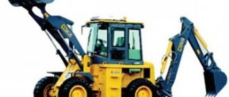
Front loader (Forklift), Backhoe loader-3CX-SUPER-ECO.
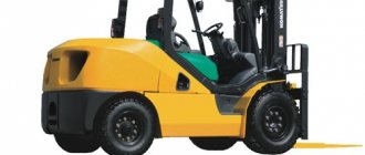
Forklifts
The main working part of this type of equipment is the fork. The machines are used to handle pallets, boxes and other types of unit loads. The design of the forks includes 2 metal strips bent at right angles. The forks are fixed on a lift, which can be located either in front or on the side.
Main characteristics of forklifts:
- Fork lifting capacity – 10 tons or more;
- Load lifting height – 1.5-5.5 m;
- The tilt angle of the lift is 3° forward and 12° backward;
- Engine power – 20-100 hp. and more.
The ability to install different types of replaceable devices allows forklifts to work with different types of loads - lumber, building materials, metal structures, etc. Pin grippers provide the ability to carry out operations with ring-shaped loads. For scooping bulk cargo, a forklift uses regular and double-jaw buckets. The jib boom allows you to work with loads that are difficult to hook with forks. The pincer gripper performs well when working with timber. Various specialized grips provide the ability to store and transport rolls, barrels, equipment in the form of drums, etc. A front-end loader may have retractable forks and a lift in the front; for side-loading equipment, the working element is located on the side. The wheeled chassis can be mounted on solid (cast) or pneumatic tires.

