Often, when purchasing warehouse equipment, namely forklifts, you can avoid foreign manufacturers. Local production is able to provide consumers with high-quality equipment that can cope with difficult tasks and prove its reliability and high technical characteristics.
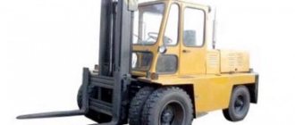
Lviv loader 41030 with a lifting capacity of 5 tons
The forklift is produced by Ukrainian, which is located in the city of Lvov. However, recently the company has often been involved in litigation related to the unsatisfactory performance of management and claims to the plant's buildings. For this reason, it is difficult to talk about the further production of both the loaders themselves and their parts.
It is impossible to find official dealers, which is why you will have to either work directly with the company or look for resellers and advertisements for the sale of used equipment.
The equipment in question is a high-capacity forklift that runs on diesel fuel. It has a reinforced chassis, cabin frame and mast, which contributes to excellent reliability and durability.
Purpose
These loaders are used to transport various goods using a forklift. It is poorly suited for storage facilities due to its large size and significant CO2 emissions. Thanks to the closed cabin, it performs well outdoors in all weather conditions.
Photo of a Lviv 5-ton loader
Due to the simplicity of the design, they can be serviced in ordinary workshops that repair tractors, tractors and trucks. While electric forklifts or foreign analogues with complex hydraulics require special equipment and trained personnel.
Hydraulic system of forklifts AP-41030, 40810
In Fig. Figure 33 shows a schematic hydraulic diagram of the forklift and steering control of the AP-40810, 41030 Lev loaders. The hydraulic steering circuit is described above. The hydraulic circuit of the forklift consists of two lifting cylinders Ts1, Ts2, two tilt cylinders TsZ, Ts4, hydraulic distributor P, hydraulic pump H2, hydraulic shut-off valves K5, K6, flow regulator RP, hydraulic tank B and hydraulic lines. The following can be installed on the forklift: Hydraulic distributors type РХ 80-1ВАА-1-1-1, RS 20T3-03, PC 162-00000-15, 4045Е-4612010-10, ЗР80, 2Р80. The operation of the forklift occurs as follows: Fig. 33. Hydraulic diagram of the Lviv loader AP-41030, 40810 B-hydraulic tank; H1-steering pump; H2-forklift drive pump; P - hydraulic distributor; Ts1, Ts2 - lifting hydraulic cylinders; TsZ, Ts4 - tilt hydraulic cylinders; C5-steering hydraulic cylinder; K1, K2, KZ, K4 - back-throttle valves; K5, Kb-hydraulic shut-off valves; RP - flow regulator; F1-pressure filter; F2-filter filler neck; A 1-hydrostatic steering mechanism; A2-safety block; HV shut-off valve; MS-hydraulic pressure gauge. The working fluid from hydraulic tank B is sucked up by pump H2 and sent to the hydraulic distributor, from where, depending on the position of the spools, it is sent to the working cavities of the hydraulic cylinders or returned back to the hydraulic tank. The line connecting the lift cylinders C1 and C2 with the hydraulic distributor includes a flow regulator RP, which passes the entire flow of working fluid into the cylinders and maintains a given flow of working fluid from the cylinders to drain, regardless of the load, i.e. ensures a constant lowering speed of the carriage and load lifter. The hydraulic shut-off valve is designed to prevent the rapid flow of working fluid from the cavity of the lifting hydraulic cylinder in the event of a break in the hydraulic line and is a unit screwed directly into the supply fitting of the hydraulic cylinder. If the hydraulic line breaks, the flow of working fluid, overcoming the force of the spring 3 (Fig. 41), presses the throttle washer 2 to the housing 6, thereby ensuring a flow rate of no more than 16/l/min. In the hydraulic system of the tilt cylinders of the Lviv loader AP-41030, 40810, four check valves Kl, K2, KZ, K4 are screwed in, limiting the speed of tilting the forklift forward and backward. The pressure of the working fluid pumped into the actuator cylinders by the pump can, if necessary, be controlled by a pressure gauge МН1 connected to fitting Ш1. Checking the pressure of the working fluid in the forklift system During TO-2, check the pressure of the working fluid in the system, for which it is necessary: - warm up the working fluid to a temperature of plus 30-50°C; — connect a pressure gauge with a tap to fitting Ш1 (see Fig. 33); — put the hydraulic distributor lever, which controls the tilt cylinders TsZ, Ts4, in the “backward tilt” position and, at the extreme position of the load lifter, without releasing the lever, measure the pressure using the MH1 pressure gauge. — the pressure gauge reading should be 18 ± 0.5 MPa (180 ± 5 kgf/cm2) — if the pressure gauge reading does not correspond to 18 ± 0.5 MPa, adjust the hydraulic distributor; — after taking the pressure readings, release the hydraulic distributor lever, stop the engine, disconnect the pressure gauge and close the hole in fitting Ш1 with a plug; — to check the pressure in the steering system, connect a pressure gauge with a tap to fitting Ш2. — the pressure gauge reading should be 12.5 ±0.5 MPa (125 ±5 kgf/cm2). Hydraulic tank for working fluid Fig. 34. Hydraulic tank (oil tank) 1 - breather; 2-filter; 3- tank body; 4-tie tape; 5- plug; 6- bracket; a, b-levels. The hydraulic tank of the AP-41030, 40810 loader is a welded metal vessel. Its body has a filler neck with a filter and a breather. The hydraulic tank is shown in Fig. 34. The oil tank does not require special maintenance. It is necessary to ensure that there are no external leaks of fluid and maintain a constant level. To control the level in the tank, the filler filter has indicators for the upper “a” and lower “b” liquid levels. Liquid is poured into the tank up to the upper “a” of the level indicator. Above the indicator “a” and below the indicator “b”, filling the tank is not allowed. Hydraulic system pressure filter Fig. 35. Forklift hydraulic pressure filter AP-40810, 41030 1-cup; 2-gasket; 3-regulating washer; 4.12 springs; 5-ball valve; 6-head; 7,8-O-rings; 9-filtering element; 10-body; 11 - support. Pressure filter F1 (Fig. 35) with bypass valve 3 is designed to protect against contamination by mechanical particles of the hydraulic steering mechanism. Filtration fineness 25 microns. Filter element 9, sealed with seals 7 and 8, is pressed by spring force 1 to head 6, in which glass 1 with bypass valve 5 is mounted. The valve opening pressure is 0.3 MPa (3 kgf/cm2). The arrow on the filter head shows the direction of flow. The working fluid enters the middle of the housing 10 through the inlet, is cleaned by passing through the filter element 9, and is supplied clean to the steering mechanism. As the filter element becomes dirty, the pressure drop across it increases and reaches the pressure at which the valve begins to open. In this case, part of the flow of working fluid, bypassing the filter element, will be supplied uncleaned to the steering mechanism. This may lead to problems with its operation. The paper filter element “Regotmass 635-1-06-UHL2” must be replaced after running in the machine after 375 operating hours of the forklift (at the third maintenance-1). When the hydraulic system of the Lviv forklift AP-41030, 40810 operates on cold oil in winter, part of the working fluid flow will also be supplied uncleaned to the steering mechanism, since the throughput of the filter element decreases with an increase in the viscosity of the working fluid as the temperature decreases. It is recommended to start work after the hydraulic system oil has warmed up to operating temperature. To replace the filter element, it is necessary to clamp the low pressure hoses and unscrew the filter housing with the filter element. When screwing on the filter housing after replacing the filter element, care must be taken not to damage the O-ring of the filter housing and filter element.
________________________________________________________________________________
Spare parts for Lviv loaders 4014, 40814, 40810, 4081, 41030 are shipped to all cities of Russia: Kemerovo, Ekaterinburg, Chelyabinsk, Novosibirsk, Ulan-Ude, Kirov, Perm, Krasnoyarsk, Irkutsk, Omsk, Barnaul, Tomsk, Bratsk, Tyumen , Lysva, Novokuznetsk, Miass, Serov, Chita, Berezovsky, Mezhdurechensk, Nizhny Tagil, Biysk, Minusinsk, Satka, Kurgan, Novy Urengoy, Norilsk, Noyabrsk, Oktyabrsky, Orenburg, Orsk, Prokopyevsk, Prokhladny, Pskov, Rubtsovsk, Rybinsk, Ryazan , Salavat, Saransk, Sarapul, Severodvinsk, Sibay, Sochi, Stavropol, Stary Oskol, Sterlitamak, Surgut, Syzran, Taganrog, Tambov, Tobolsk, Ust-Ilimsk, Ukhta, Khabarovsk, Khanty-Mansiysk, Chistopol, Chusovoy, Shadrinsk, Shakhty, Shelekhov, Elektrostal, Elista, Engels, Yakutsk, Vologda, Nizhny Novgorod, St. Petersburg, Belgorod, Orel, Kazan, Rostov-on-Don, Voronezh, Bryansk, Krasnodar, Saratov, Murmansk, Tula, Noginsk, Volgograd, Ivanovo, Penza , Cheboksary, Volzhsky, Yaroslavl, Syktyvkar, Izhevsk, Samara, Makhachkala, Volzhsk, Yoshkar-Ola, Sokol, Ufa, Arkhangelsk, Tver, Podolsk, Ulyanovsk, Smolensk, Togliatti, Vladikavkaz, Petrozavodsk, Kursk, Vladimir, Cherepovets, Naberezhnye Chelny and etc.
Design Features
The transmission in the Lviv loader 41030 with a lifting capacity of 5 tons is traditional, namely a mechanical 4-speed. Such a system can provide a lower cost for the loader itself, and also eliminates the need for hydraulic fluid in hydromechanical transmissions. However, in comparison with the same hydraulics, it cannot provide smooth, shock-free acceleration. The system is quite reliable and easy to repair.
Four-cylinder diesel engine. Has good performance. The lubrication system is combined, and the cooling is water.
The forklift steering system adopts a hydrostatic system, which provides precise and easy control, as well as good reliability.
But the brake system does not have hydraulics: conventional drum brakes are used, which require regular maintenance and more careful handling.
The lifting mechanism is standard, telescopic. The hydraulic distributor can be three-section or two-section. The standard lifting height is 3300 mm, but can be equipped with a lifting mechanism of 4500 mm.
The loader can be equipped with various interchangeable attachments, such as a 0.57 m3 bucket and a boom with a hook.
Hydraulic diagram of the Lviv loader forklift
Of course, the design of Lviv forklifts 5 tons of these forklifts is quite simple and does not provide a modern level of comfort, smooth acceleration, as well as accuracy and ease of control. However, it also has its advantages: the low price of loaders, reliable proven units, ease of maintenance and repair. And in the hands of a trained and experienced operator, the loaders will not be inferior to the latest foreign analogues.
Hydraulic system of Lviv forklifts and its components
Hydraulic system of the forklift and steering of forklifts AP-4081, AP-40810, AP-41015, Lev 41030 The hydraulic circuit of the forklift of forklifts AP-40810, 41015, 41030 consists of two lifting hydraulic cylinders, two tilting hydraulic cylinders, a hydraulic distributor, an NSh-71 pump, hydraulic valves cut-off , flow regulator, oil tank and hydraulic lines. PRICES FOR HYDRAULIC SYSTEM COMPONENTS OF LVIV FORKLIFTS The operation of the forklift occurs as follows: The working fluid from the oil (hydraulic) tank is sucked by the NSh-71 / NSh-100 pump and sent to the hydraulic distributor РХ-80 or 3Р80, from where, depending on the position of the spools, it is sent to the working cavities of the hydraulic cylinders or returns back to the tank.
Oil tank assembly 4014-4615010-11 (loader AP-4014, 40814, 4081, 40810, 40811, 40816, 41015, 41030 Lev) 1 - Filler neck filter 4014-4615070-11 2 - Breather assembly 4014 -4615050-11 3 - Plug 353052 4 - Oil tank assembly 4014-4615010-11 5 - Tightening tape assembly 4014-1101106 6 - Washer 12 252137 7 - Nut M12 250514 8 - Washer 10 252136 9 - Nut M10 2505 12 10 — Bracket assembly 4014 -1101102 11 — Bolt M12x40 201544 12 — Bolt M12x25 201538 A flow regulator is included in the hydraulic system line of Lviv loaders connecting the lifting hydraulic cylinders with the hydraulic distributor, which passes the entire flow of working fluid into the hydraulic cylinders and maintains a given flow of working fluid from the hydraulic cylinders to drain, regardless of the load , that is, it ensures a constant lowering speed of the carriage and load lifter. The shut-off valve is designed to prevent rapid flow of working fluid from the cavity of the lifting hydraulic cylinders of Lviv loaders AP-40814, 40810, 41030 in the event of a break in the hydraulic line and is a unit screwed directly into the supply fitting of the lifting hydraulic cylinder. If the hydraulic line breaks, the flow of working fluid, overcoming the force of the spring, presses the throttle washer to the body, thereby ensuring a flow rate of no more than 16 l/min. In the hydraulic system of the hydraulic tilt cylinders of Lvov forklifts, back-throttle valves are screwed in, which limit the speed of tilting the forklift forward and backward. The pressure of the working fluid in the forklift system of the Lev 41030 forklift with two lifting hydraulic cylinders (rod diameter 70 mm) should be 18 MPa
Schematic hydraulic diagram of the Lviv forklift AP-40810, 41015, LEV 41030 B – hydraulic tank H1 – steering pump NSh-10 H2 – forklift drive pump NSh-71 or NSh-100 R – hydraulic distributor RH-80, 3R80 Ts1, Ts2 – hydraulic cylinders lift C3, C4 – tilt hydraulic cylinders C5 – steering hydraulic cylinder K1, K2, K3, K4 – back-throttle valves K5, K6 – shut-off valves RP – flow regulator F1 – pressure filter F2 – filler neck filter A1 – hydrostatic steering mechanism – pump dispenser (hydraulic steering wheel) D160 14.20 A2 - safety block VN - shut-off valve MN - pressure gauge Setting the hydraulic system pressure for Lviv forklift models Lviv forklift 4045, 4014, 4043, 40811, 40816 The pressure in the hydraulic system of the forklift (boom, mast) should be set to: - 12 MPa , if the forklift has one lifting hydraulic cylinder with a rod diameter of 125 mm. The setting is made by turning the safety valve of the hydraulic distributor. To the right (clockwise) – increase in pressure, to the left (counterclockwise) – decrease in pressure. The set pressure is checked with a pressure gauge. It is known from practice that one revolution of the safety valve is approximately equal to 2 MPa. — 14.5 MPa, if the forklift has one lifting hydraulic cylinder with a rod diameter of 110 mm. The setting is made by turning the safety valve of the hydraulic distributor. Lviv forklift 40814, 40810, 41015, 41030 The pressure in the hydraulic system of the forklift (boom, mast) should be set to: - 18 MPa, the forklift has two lifting hydraulic cylinders with a rod diameter of 70 mm. Oil flow regulator The flow regulator of the hydraulic system of the Lviv loader is a unit screwed directly into the body of the lifting hydraulic cylinders, passing the entire flow of working fluid into the hydraulic cylinder and maintaining a constant flow of working fluid from it to drain, regardless of the load. Flow regulator (4085-4672) for loaders AP-40814, 40810, 41015, 41030 1-body; 2-spring; 3-spool; 4-throttle washer; 5-stop ring. When the lever and spool of the hydraulic distributor are moved to the “lift” position, the flow of working fluid through the holes in the housing 1 (Fig.), the channels in the spool 3, the hole in the throttle washer 4 passes into the cavity of the hydraulic cylinder. When the lever and valve spool are moved to the “lowering” position, the flow of working fluid from the hydraulic cylinder through the hole in the throttle washer 4, the channels in the spool 3 and the holes in the housing 1 is directed to drain. Spool 3 is loaded by spring 2, the force of which is balanced by the pressure drop created by the resistance of the hole in the throttle washer 4. If the flow rate of the working fluid increases, then the pressure drop also increases, as a result of which the throttle washer with the spool moves to the left, and the spool partially blocks the windows in housing 1 , reducing the flow rate of the working fluid to the value for which the flow regulator is designed. When the flow rate decreases, spool 3 with throttle washer 4 will move to the right, thereby reducing the total resistance of the windows in housing 1. Back-throttle valve of the tilt cylinder The tilt cylinder system of Lviv loaders AP-4014, 40814, 40810, 41015, 40816, 41030 Lev has been reintroduced - throttling valves, which are designed to ensure a smooth tilt of the forklift forward and backward. Valve 2 (Fig.) freely allows the flow of working fluid in one direction and throttles it in the opposite direction. The flow of working fluid directed through hole A of housing 1 pushes valve 2 down until it stops against sleeve 3 and flows freely through the external channels of the valve to the tilt cylinder through hole B. The flow of working fluid directed through hole B moves valve 2 up and presses it to the trace of housing 1, is throttled in the throttle hole B of valve B2, enters hole A and then into the hydraulic system.
Back-throttle valve of the tilt cylinder of Lviv loaders 1 – housing; 2 – valve; 3 – bushing; A, B, C – holes. Fine drain filter (F1-20/25 K) Fine drain filter (F1-20/25 K) is designed to filter the working fluid from contaminants formed during operation and coming from outside. The working fluid from the drain line through the inlet to the filter cover 6 (Fig.) enters the housing cavity and, having passed through the filter element 7, is directed to the central part of the filter element, and from there to the outlet channel of the housing pipe. When the pressure drop across the filter element increases due to its clogging, safety valve 4 opens and the flow of working fluid, bypassing the filter element, is directed to drain through the outlet channel of the pipe into the hydraulic tank. A dirty filter element must be replaced. Replacement of the filter element is carried out as follows: Pinch the low pressure outlet hose from the filter housing to the oil tank, rotate filter pipe 8 to the left to unscrew it from the cover and lower it down. Then replace the filter element. After replacing the filter element, screw the pipe into the cover by rotating it to the right. Release the low pressure hose from squeezing. Fine drain filter (F1-20/25 K) 1 – spring; 2 – body; 3 – seal; 4 – safety valve; 5 – plug; 6 – cover; 7 – filter element; 8 – pipe. Hydraulic shut-off valve for the lifting cylinder of the Lviv loader The hydraulic shut-off valve for the AP-4014, 40814, 40810, 41015, 40816, 41030 Lev loaders is designed to prevent the rapid flow of working fluid from the cavity of the lifting cylinder when the hydraulic line breaks and is a unit screwed directly into the supply fitting of the hydraulic cylinder. If the hydraulic line breaks, the flow of working fluid, overcoming the force of spring 3, presses washer 2 to body 6, thereby ensuring a flow rate of no more than 16 l/min. Hydraulic shut-off valve (lift cylinder valve) 4088-4690010 1 – nut; 2 – washer-throttle; 3 – spring; 4 – washer; 5 – screw; 6 – body; a – gap 2+º¹mm.
Hydraulic system filter assembly 4088-4616110 1 — Head 4088-4616121 2 — Ring 025-031-36-2-2 3 — Cover 4088-4616111 4 — Spring 4088-4616112 5 — Housing 4088-4616130 6 — Filter element cozy 605-1 -06 Regotmas 7 — Ring 021-024-19-2-2 8 — Ring 080-086-36-2-2 9 — Ball B19.05-200 10 — Spring 4088-4616124 11 — Gasket 4088-4616123 12 — Glass 4088-4616122 Valve block for Lviv loaders AP-4045, 4014 The ability to regulate the lowering speed by changing the pump flow is realized by installing a valve block for the lifting cylinder, which is fixed directly to the cylinder. The valve block of Lviv loaders AP-4045, 4014 with a lifting hydraulic cylinder with a rod diameter of 125 mm performs four functions: it allows the entire fluid flow into the cylinder with minimal resistance and locks the fluid in the cylinder when the distributor spool is in the neutral position and, if the supply hydraulic line is damaged, regulates the fluid flow leaving the cylinder using a controlled throttle valve, with the flow from the cylinder proportional to the pump performance; provides emergency lowering of cargo in case of failure of the hydraulic drive (hydraulic pump, pipelines) of the engine. The valve block of Lviv loaders AP-4045, 4014 consists of a housing 10, which houses a check valve 4 with a rod 5 and a spring 6, a controlled valve / with a spring 2, fittings 3 and 9, covers, valve seats and seals. A damper nut with a calibrated hole is fixed in fitting 9. By switching the distributor to lift, the liquid is directed through fitting 3 to the end of valve 4, compressing the spring with pressure, opens it and enters cavity A of the cylinder. By the force of spring 2, valve 1 is pressed tightly to the seat. There is no pressure in cavity B.
Valve block 4014-467202010 for Lviv loaders AP-4045, 4014 with a lifting hydraulic cylinder with a rod diameter of 125 mm 1.4 - valves, 2, 6 - springs. 3.9 - fittings. 5 — rod, 7 — lock nut; 8 - cap, 10 - body In the neutral position of the distributor spool, the pressure of the liquid in the cylinder and the force of the spring, valve 4 is pressed tightly to the seat; valve 1 is also pressed to its seat by spring 2, eliminating fluid leakage from the cylinder. By switching the distributor to lower, the pressure hydraulic line from the pump is connected to cavity B and through the throttle washer to drain C, and cavity D is connected to the drain. The higher the pump performance, the greater the pressure created in cavity B, as the pressure drop across the throttle plate increases. By liquid pressure, valve / moves to the left, connecting cavity A with cavity D, and the liquid is transferred through the annular gap into the tank. When the valve moves, the compression of the spring and the pressure in cavity B increase, since the hydraulic resistance of the drain line increases with increasing flow rate in proportion to the opening of the valve, and the pressure in cavity B is balanced. The valve movement will also decrease, and the valve will move to the right under the action of spring 2 and the pressure in cavity B , partially blocking the annular gap. If at the same time we reduce the pump flow and thereby the pressure in front of the damper nut, then the pressure in cavity B will also decrease and, with the force of spring 2, the valve will move to the right, partially closing the annular gap.
Valve block assembly 4014-467202010-01 (for Lviv loaders AP-4045, 4014 with a lifting hydraulic cylinder with a rod diameter of 125 mm) 1 - Cotter pin wire 0.8x250 258228-P29 2 - Fitting 4014-4672031-10 3 - O-ring 040 -045-30-2-2 4 — Valve seat 4014-4672034 5 — O-ring 025-030-30-2-2 6 — O-ring 040-045-30-2-2 7 — Rivet 3x6 255024-P29 8 — Plate 4014-3904036 9 — Body 4014-4672015-01 10 — Valve assembly 4014-4672012 11 — Valve 4014-4672050 12 — Rod 4014-4672042 13 — Ring 4014-4672048 14 — Shay ba 4014-4672046 15 — Blind nut 4014- 4672036 16 — Nut M12x1.25 250615-P29 17 — Washer 4051А-4675020 18 — Stop 4014-4672040 19 — O-ring 033-038-30-2-2 20 — Spring 4051А-4675038 21 — Valve 4014-4672016-01 22 — O-ring 020-025-30-2-2 23 — Sleeve 4014-4672018 24 — Cotter pin wire 0.8x125 258223-P29 25 — Seal 4000М-4612120 26 — Damper 4014-4672035 27 — Fitting 40 14-4672013 28 - Bolt М12х1,25х80 205469-П29 29 — Washer 12 252137-П29 30 — Washer 4014-4672020 31 — Spring 4014П-4672022 32 — Stop 4014-4672025-02
Hydraulic drives of loaders AP-4014, 40814, 40811, 40816 1 — Angle 4085-4617330-20 2 — Tilt cylinder 4081-4614010 3 — Adapter 4085-3408080 4 — Gasket 4014М-4617180 5 — Valve back-throttle 4084-4617100 6 – Sleeve high pressure 4085-4617115 7 - Pipe 4014M-4617137-20 8 - Pressure valve 4014M-4617055-35 9 - Hose NA-315/9 10 - Tee 4014M-4617145-21 11 - Clamp 4000ME-4617028 12 - Sleeve NA-315 /15 13 — Oil tank 4014-4615010-11 14 — Sleeve NA-315/14 15 — Clamp 4045ME-4617028 16 — Elbow 4014-4617200 17 — Hose 120-1303029 18 — Elbow 4014-4617202 19 — Sleeve NA-315/ 24 20 — Sleeve 4014М-4617154 21 — Clamp 4000МЭ-4617028 22 — Pipe 4014-4617022-10 23 — Angular coupling 4014-4617032-B 24 — Ring У-70х65-2 25 — Hydraulic pump NSh71-3-2 26 - Ring seal NSh46-0505037 27 — Hydraulic pump NSh32U-2 28 — Angular coupling NSh32-0303035-V 29 — Bolt M8x50 201468-P29 30 — Fitting NA-323/06 31 — Pipe 4014М-4617030 32 — Flange 4014- 4617064 33 — Pipe 4014M-4617135 34 - Sleeve 4085-4617210 35 - Pipe 4014M-4617050 36 - Pipe 4014M-4617052 37 - Sleeve NA-315/11 38 - Fitting NA-323-10 39 - Portioner 4014M-46770 10 40 — Fitting 4085-3408060 41 — Hydraulic cylinder 4085-3429010-10 42 — Adapter 4085-3408080 43 — Gasket 4014М-4617180 44 — Bolt 4085-3408045 45 — Filter 4085-4616010 46 — Sleeve 4085-4617120 47 — Sleeve NA-315/20 48 – Pipe 4014M- 4617033 49 - Pipe 4014M-4617037 50 - Filter F1-20/25K 51 - Hose NA-315/4 52 - Hose NA-315/9 53 - Pipe 4014M-4617042 54 - Fitting 4085-4617207-20 Fitting 4081- 4617204- 40 55 — Pipe 4014М-4617045 56 — Pipe 4014М-4617016-35 57 — Hydrostatic steering control ХУ145-0/1 58 — Hydraulic distributor РХ80-1ВАА-1-1-1Р2 59 — Sleeve 4085-4617210 60 — Hydraulic pipeline 4081-4 617125- 20 61 — Adapter 4014М-4617145 62 — Gasket М36 4085-4672360 63 — Flow regulator 4085-4672010 64 — Lifting cylinder 4081-4613010 Lifting cylinder 4081-4613011 65 — Pipe 4014М-4617 132-20 66 — Pipe 4014М-4617560-35 67 — Fitting 4014-4672013 68 — Valve block 4014-4672010-01 69 — Fitting 4014-4672031 70 — Elbow NA-330/08 71 — Sleeve 4085-4617125 72 — Lifting cylinder 4081-4613012 Lifting cylinder 4081-4613013 73 - Pipe 4014M -4617140-20 Pipe 4014M-4617140-40 74 — Fitting 4085-4617204-20 Fitting 4085-3408060 75 — Ring 024-030-36-2-2 Gasket M18 4014М-4617180 76 — Fitting 4085- 4617207-20 Fitting 4081- 4617207-40 77 — Gasket M22 4081-4617220-40 78 — Plug 4085-4617310 Plug 4081-4617210-40 79 — Gasket 4014М-4617180
Hydraulic pipelines AP-40810, 41015 1 — Gasket 4085-4617270 2 — Valve assembly 4088-4690010 3 — Adapter 40814-4617070-40 4 — High-pressure hose (HPR) 4085-4617120 5 — High-pressure hose (HPR) 40 85-4617115 6 — Pipe 40814-4617132 7 — Check throttling valve 4084-4617100 8 — Gasket 4014М-4617180 9 — Plug 4085-4617310-20 10 — Ring 024-030-36-2-2 11 — Fitting 4019-4617 180 12 — Ring sealing 030-035-30-2-2 13 — Elbow 4085-4617330-20 14 — Durite sleeve NA-315/15 15 — Clamp 4000-1303029 16 — Hydraulic tank (oil) 4014-4615010-11 17 — Hose 120- 1303029 18 — Elbow 4014-4617200 19 — Durite sleeve NA-315/26 20 — Clamp 4045E-4617028 21 — Hydraulic gear pump NSh-71 22 — O-ring NSh46-0505040 23 — Fitting 4019-4617 180 24 — Pipe 40810-4617135 25 — Pipe 40810-4617145 25 — Pipe 40810-4617145 26 — High pressure hose (HHP) 4085-4617210 27 — Pipe 40814-4617140 28 — Pipe 4014М-4617137-20 29 — Fitting 4085-4617 207-20 30 — Fitting 4085-4617204 -20 31 — Hydraulic distributor RS-162-15 32 — Pipe 40814-4617130-40 33 — Tilt hydraulic cylinder 4081-4614010 34 — Adapter 4085-3408080 35 — Tee 40814-4617055-40 36 — Gasket 4085-4 672360 37 - Flow regulator 4088 -4672010 38 — Lifting hydraulic cylinder 40814-4613010-10
________________________________________________________________________________
Spare parts for Lviv loaders 4014, 40814, 40810, 4081, 41030 are shipped to all cities of Russia: Kemerovo, Yekaterinburg, Chelyabinsk, Novosibirsk, Ulan-Ude, Kirov, Perm ь, Krasnoyarsk, Irkutsk, Omsk, Barnaul, Tomsk, Bratsk, Tyumen, Lysva, Novokuznetsk, Miass, Serov, Chita, Berezovsky, Mezhdurechensk, Nizhny Tagil, Biysk, Minusinsk, Satka, Kurgan, Vologda, Nizhny Novgorod, Abakan, Almetyevsk, Anapa, Angarsk, Anzhero-Sudzhensk, Apatity, Arzamas, Armavir, Astrakhan, Achinsk, Balakovo, Bataysk, Belebey, Belovo, Beloretsk, Berdsk, Berezniki, Blagoveshchensk, Buguruslan, Buzuluk, Velikiye Luki, Veliky Novgorod, Volgodonsk, Votkinsk, Glazov, Dzerzhinsk, Dimitrovgrad, Yelabuga, Zelenogorsk, Zelenodolsk, Zlatoust, Iskitim, Ishim, Ishimbay, Kaluga, Kamensk-Shakhtinsky, St. Petersburg, Belgorod, Orel, Kazan, Rostov-on-Don, Voronezh, Bryansk, Krasnodar, Saratov, Murmansk, Tula, Noginsk, Volgograd, Ivanovo, Penza, Cheboksary, Volzhsky, Yaroslavl, Syktyvkar, Izhevsk, Samara, Makhachkala, Volzhsk, Yoshkar-Ola, Sokol, Ufa, Arkhangelsk, Tver, Podolsk, Ulyanovsk, Smolensk, Tolyatti, Vladikavkaz, Petrozavodsk, Kursk, Vladimir, Cherepovets, Naberezhnye Chelny, etc.
Specifications
Technical characteristics of the Lviv loader 41030 with a lifting capacity of 5 tons:
| Characteristics | Indicators |
| Unloading height, mm | 3300-4500 |
| Load capacity to a height of 3300 mm, kg | 5000 |
| Load capacity to heights over 3300 mm, kg | 4000 |
| Engine power, kW | 57 |
| Torque, N/m | 290,4 |
| Hydraulic pump rotation speed, rpm | 1920 |
| Hydraulic pump flow, l/min | 16 |
| Turning radius, mm | 35500 |
| Overall dimensions LxWxH (with forks), mm | 5100x2350x2650 |
| Ground clearance, mm | 200 |
In the video there is a 5 ton Lviv loader:
Hydraulic system of a forklift (using the example of a Lviv forklift)
Hydraulic oil from tank 19 enters through the suction filter 23 into the gear pump (GP) of the hydraulic distributor 24 and GP of the power steering 25, then the liquid is distributed to the power steering 30 and to the hydraulic distributor 16.
The oil entered the hydraulic distributor, controlling the levers, we redirect it using the bucket tilt cylinder control spool 15, the frame tilt cylinder control spool 17 and the boom lift cylinder control spool 18 in the desired direction. After completing the work, little is returned through the return filter 20 to the tank.
This scheme is applicable to many models of forklifts. Forklift hydraulics are one of the most important systems of a forklift; they are responsible for lifting loads.
Below is a diagram of the hydraulic system of a forklift (Lvovsky)
Let's take a closer look at the power steering
- mounting support to the frame - 26;
- cylinder piston steering gear - 27;
- cylinder - 28;
- spool - 29;
- spool body - 30;
- emergency valve - 31;
- pressure reducing valve - 32;
- ball pin of the longitudinal steering rod of the bipod for controlling the spools - 33.
Basic data of the hydraulic system of the Lviv loader
The load lifter cylinders are driven by a gear pump NSh-46U, with a capacity of 46 cm3/rev. from the engine crankshaft through the cardan transmission and gearbox. The operating pressure of the pump is up to 100 kg/cm3, at an operating speed of the pump shaft of 1100-1850 rpm.
The hydraulic pump drive gearbox is single-stage with cylindrical helical gears. Gear ratio 1.65.
The hydraulic distributor is a three-spool valve with bypass and safety valves. The safety valve is adjusted to a pressure of 120-125 kgf/cm2.
The lifting cylinder is a single-acting plunger type, stroke 2000 mm. The plunger diameter of model 4043M is 100 mm, model 4045N is 130 mm.
Tilt cylinders are piston type, double acting. Cylinder diameter 120 mm. The piston stroke is 130 mm. Two cylinders are installed: upper and lower.
The oil tank is welded, common to the forklift and power steering cylinder drive systems with strainers in the filler neck and drain pipe. Tank capacity 105 l. The capacity of the hydraulic drive system with the capacity of all cylinders of the model 4043M loader is 15 l, model 4045M is 18 l. The capacity of the hydraulic pump drive gearbox is 0.5 l.