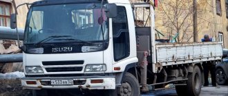
Device, technical equipment and work process.
A single-bucket excavator is a type of equipment designed to perform a variety of excavation and general construction operations. The production cycle consists of six stages:
- Cutting the soil layer and filling the bucket part.
- Lifting the filled bucket for unimpeded transport to the dumping site.
- Raising the boom to the unloading area. Sometimes the rotation of the boom is combined with the lifting of the bucket.
- Emptying cut rocks into dump trucks or dumps.
- Return to the cutting site.
- Feeding the bucket part for cutting material.
The movement of single-bucket equipment is carried out through the use of several types of running equipment:
- Crawler. This type provides increased maneuverability and is used for work in difficult terrain conditions.
- Pneumatic.
- Walking. Due to its small mass, it reduces the pressure exerted on the surface and increases stability.
- Rail-walking. Increases maneuverability and reduces pressure on the supporting surface.
Cutting and collecting rock takes 15-30% of the working time of the entire production cycle, so soil development with multi-bucket excavators will be significantly higher in productivity. This occurs due to the continuity of soil sampling with several buckets. However, multi-bucket models have restrictions on the size of the rock being lifted - the size of the lifted inclusions should not exceed 0.2 of the total width of the bucket. In single-bucket technology there are no such restrictions.
Optional equipment
The single-bucket machine base provides the use of four main types of equipment.
In addition to the possibility of using a dragline, grab, front and back shovels, this construction equipment can be equipped with the following components:
- Bucket rotator. A mechanism that allows you to quickly transition from front shovel operation to backhoe mode. Most often found on European models: for example, on Czechoslovakian UDS-114 models.
- Slope planner. A separate type of “backhoe” type bucket used for constructing slopes. It ensures the movement of the bucket cutting edge at a certain angle. To use the scheduler, you must install automated control.
- Ripper. It is used to destroy structures, break up asphalt or concrete pavement, and perform operations with soils from group III with a dragline excavator.
- Strug. The boom along which the cart with the bucket “runs”. Used in planning work.
Types of Bucket Excavators
According to their purpose, single-bucket models are divided into three large categories:
- Construction. Universal equipment with full rotation and bucket capacity of 0.15-2 m3. Versatility is ensured by the ability to install replaceable components for various manipulations. The development of soil starting from category III is often carried out by an excavator using replaceable components.
- Career. Semi-universal machines or special shovels with a shortened boom. The bucket capacity of semi-universal models ranges from 2 to 8 m3. They are used for manipulation on difficult terrain, often used in mining.
- Overburden. Machines with a bucket whose capacity exceeds 6 m3. They are used for “overburden” – cutting off the upper layers of rock. As a rule, they are equipped with extended equipment that increases the working radius. Stripping machines do not have the ability to install replacement equipment. Overburden construction equipment includes walking draglines with buckets with a capacity of 4 to 80 m3, used for digging trenches, filling dams, and constructing pits.
Based on the possibility of operation with various types of additional devices, single-bucket machines are divided into three types :
- Universal. They have at least 4 types of replaceable equipment.
- Semi-universal. Machines with a bucket part capacity of no more than 4 - 6 m3. It is possible to install two or three types of additional modifications on semi-universal models.
- Specialized. Bucket capacity is more than 4 m3. They are produced with one equipment modification, without the possibility of change.
General schemes of work
Based on the type of organization of routes for removing waste material, all excavation work is divided into two large groups:
- Transport-free. When carrying out this scheme, the soil layer is cut off and placed in an earthen structure; vehicles are not involved. There are two types of this type of work. With a simple scheme without the participation of additional transport, the cut layers are placed in dumps without subsequent removal. In complex cases, a temporary dump is used for laying, followed by re-excavation (moving) of the raised rock.
- Transport. After lifting the soil, it is loaded into vehicles and moved to a given location. With a transport scheme, there are two possible routes for road transport: dead-end or through.
The choice of excavation scheme is carried out taking into account the characteristics of the construction site.
For example, in the laying of oil and gas pipeline structures, non-transportation schemes have an advantage, and in the construction of industrial and residential complexes with the possibility of arranging normal unloading routes, transport schemes have an advantage.
Development is carried out by creating special trenches - penetrations. Sampling is carried out with the construction of frontal or lateral trench penetrations. When carrying out frontal excavation, sampling is carried out on three parts of the existing site - two sidewalls and an end slope.
There are two types of side penetrations:
- Closed. Here the excavator axis is located to the right or left of the excavation section. In this case, three slopes are developed - the side sections and the end slope.
- Open. There is a gradual shift in the direction of the strip with rock sampling from the sides and the end slope.
Preparation stages before pit development
Initially, a scheme and plan are developed. To draw up a pit design, several studies and examinations are carried out, in particular, they study the composition and density of the soil, calculate the static load on the foundation, and determine the presence and depth of groundwater.
The last indicator is especially important, since groundwater can often become an insurmountable obstacle to construction on a particular site. If the building must nevertheless be built here, then they resort to an expensive and technologically complex operation to drain the soil, and also during construction they install water drainage systems from the foundation.
Also, the composition of the soil and the depth of subsoil flows affect the angle of inclination of the side walls of the pit or trenches.
After the diagram and plan are drawn up, they are transferred directly to the area. This means that it is necessary to do a geodetic survey and, depending on its results, determine the dimensions of the future pit or trench and mark the area for it.
Marking the site before digging a pit
This same stage involves performing landscape adjustments to the soil: existing holes are filled in, hill ledges are leveled, unused structures are demolished, and vegetation is uprooted.
Before you start digging a foundation pit with an excavator or a trench for a water supply system, you need to make sure that there are no underground communication networks running in its place.
If they exist, then their layout must be changed, communications re-routed along a different route, outside the development zone. Only after completing all the preliminary stages can you begin the excavation work itself - digging a foundation pit.
How is a pit excavated?
The most effective way to develop soil for a foundation is to use a powerful excavator. The only option when this operation is impossible is that the passage of equipment to the construction site is limited. In this case, you will have to dig trenches manually, which is much more expensive in both time and money. Experienced specialists from construction companies calculate in advance the possibility of access to the construction site and, if it is not available, a temporary road map is laid out for the delivery of equipment and materials to the site.
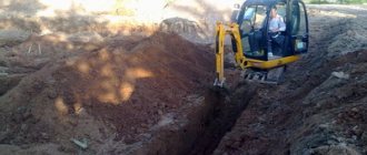
Digging a pit with an excavator
Before you start digging a pit with an excavator, you should know that the safety of the future construction will depend on the quality of the work performed. Therefore, such an important stage as digging should be entrusted exclusively to professionals, since an amateur approach in order to reduce the cost of the overall construction cost in this case is completely unjustified.
Special equipment is used to dig pits and trenches. The type of earthmoving machine is determined depending on the terrain conditions and the expected scope of work.
So, for example, in order to dig a small shallow foundation or trenches for a pipeline, a mini-excavator is used. But for significant deepenings of a large area, it is advisable to use more powerful machines - excavators on wheels or tracks, equipped with one or more buckets.
Single-bucket machines are considered the most versatile because they can be used in almost any conditions. Multi-bucket technology is used less frequently, only for the development of highly complex objects. The choice of excavator with which the work of constructing a pit or trench will be carried out is carried out individually, taking into account all the conditions and features of the object.
Work area and its arrangement
The face means the working area of single-bucket equipment, which includes a central platform with the placement of an excavator and accompanying vehicles.
The face is equipped taking into account the main parameters:
- The dimensions of the structure being built and the shape of the required pit.
- Technical indicators of the excavator used. For example, when using crawler-mounted machines, it is permissible to excavate soil in difficult terrain where increased cross-country ability is required.
- Technical characteristics of the road transport used. For example, if work is carried out in a marshy area, the face should be equipped as close as possible to the hard surface to increase the cross-country ability of vehicles.
Design of faces with subsequent sampling of material consists of correct determination of the width and depth of the face, selection of optimal installation positions of machines located on the site, sequential selection of layers and equipment of paths for moving equipment and associated transport.
If the face height is low, it is worth using a single-bucket model, supplemented by a bulldozer that rakes up soil material. The bulldozer moves it to the “excavator working area”, where hilling is carried out, creating a sufficient height of the sides of the working area.
All machines used are installed in such a way as to reduce the swing angle of the boom to a minimum - turning the excavator boom takes 70% of the time of the total production cycle.
Manufacturing jobs
Most excavators achieve precise excavation even in tight spaces. The work process may be accompanied by storage of land and removal, but with the connection of other equipment such as a dump truck. The work process manager controls the coordinated interaction of different functional groups, achieving efficiency and accuracy in the execution of operations. At the final stage, the excavation pit development technology involves cleaning the bottom. If the capabilities of a particular model of equipment allow, the operator can prepare a strong and reliable sole for the foundation. At a minimum, after the main soil sampling, loose areas and embankments are eliminated, which may subsequently shrink.
Increasing efficiency indicators during excavation
To increase productivity when carrying out excavation work, you must be guided by certain provisions:
- Calculate the digging radius, taking into account the maximum values of the equipment being used. It should not be higher than 0.7-0.9 of the largest radius of the model used.
- Combine operations to reduce production cycle time. For example, combine the rotation of the platform with the lifting of the bucket part, which is moved to the place for unloading.
- Reduce the rotation angle of the platform by bringing the transport installation site closer to the trench axis. This will help reduce the loss of working time spent turning the platform.
- Equip unloading paths, ensuring rapid movement for removal of lifted material.
- Reduce the time spent moving the excavator by planning and equipping the movement paths.
- If possible, avoid moving machines under their own power, preventing premature wear of the running gear.
- Select a bucket taking into account the rock being cut. For example, use special buckets or bucket containers of at least 1 m3 for loosened rock layers, and use containers from 0.5 to 0.8 m3 for finely crushed rock materials.
- Monitor the ratio of the carrying capacity, the distance for removal and the volume of the bucket container.
What should you consider at the initial stage?
Even before ordering a project, it is recommended to determine in general terms the parameters of the future pit and the scope of work, which will directly affect the cost of development. At the same time, the larger the structure, the lower the cost per 1 m2. And not every project with a minimum volume, in principle, involves mechanized digging - this nuance should also be taken into account.
Next, the configuration of the pit is determined - for example, whether there will be a basement in it. Some types of foundation require the creation of a trench without completely excavating the area under the house. However, the presence of a basement or cellar in the plan means that soil will have to be removed along the entire perimeter. Today, it is increasingly practiced to excavate a foundation pit with an excavator for a foundation of complex shape with steps, kinks and ledges. These design elements should also be calculated in advance so that they are performed by professional equipment.
Development of soil models with a straight shovel
A straight shovel is a type of bucket container with a completely open top.
It is rigidly attached to the handle, which is connected to the boom using a hinge. The shovel is moved forward due to the action of the pressure mechanism, and emptying is done by completely opening the bottom. The model with a straight shovel cuts and lifts in the direction of its own motion in front of the bucket part, and then smoothly moves forward by the amount of the specified handle stroke. The development of the site is carried out until the required profile is formed by creating successive trenches.
Excavation of soil with a straight shovel excavator is carried out by carrying out trenches of two categories:
- Lateral branches with dumping of cut and raised rock into a vehicle or dump located in the direction of movement of the equipment. The height of the machines in the working area determines the type of lateral penetration: single-tier with the cars located on the same level as the excavator, and two-tier with the cars placed at different heights.
- Frontal penetrations, during the creation of which the transport for unloading is installed behind the operating equipment.
The side face is advantageous by reducing the turning angle, convenient supply of vehicles for pouring the selected material, which increases productivity. But, when operating a side face, the volume of rock lifted from one area decreases, leading to an increase in the number of machine movements.
With the frontal type of face, there is a need to drive dump trucks in reverse and install vehicles behind the operating equipment, which leads to an increase in the turning angle. This causes longer production cycles, increased time costs and reduced efficiency. At the same time, the frontal face device increases the volume of material being lifted, reducing the number of movements.
The installation of side penetrations is carried out during development in quarries and the formation of excavations with subsequent loading of waste material onto vehicles.
The scope of construction of frontal faces is somewhat wider:
- The first penetrations in the development of excavations and quarries.
- Work in confined spaces that impede the arrangement of loading routes.
- Lifting rock from rock excavations.
- Carrying out manipulations in autumn-winter periods on frozen soils.
All work is carried out only using a transport scheme. This is due to the fact that the small linear dimensions of models with a “straight shovel” bucket part do not allow the use of transport-free rock dumping.
Development of a design solution
Organization of work on the construction of a pit involves the initial preparation of two documents:
- Work execution project (WPP).
- Technological map for pit development.
As for the first document, it contains explanatory notes, plans and drawings with detailed information on earthmoving work in specific conditions. When creating a project, the individual preferences of the customer and regulatory technical and architectural requirements are taken into account. A typical PPR for excavation pit development with an excavator, in particular, contains a set of initial data, a step-by-step description of the work, fencing design characteristics, a schedule, etc.
The technological map determines the sequence of work operations. A list of geodetic and planning activities, the process of soil development with loading and unloading operations and subsequent refinement with cleaning of the base of the constructed pit are described separately.
Excavation of models with a backhoe
A backhoe is a bucket container with a “bottom” open part and a cutting front edge.
It is attached to the boom with a swivel joint; there is no pressure mechanism. Filling with rock occurs as the container is “pulled back.” Unloading is carried out at the moment of lifting with simultaneous turning over. This variety is used in the development of a site located below the level of the base site. In trenches with a backhoe, it is advisable to use end- or side-type faces, which allow digging out a bed for underground utility equipment and digging small pits. Rigid fastening of the bucket part allows trenches with vertical walls to be torn off, reducing the risk of side parts collapsing. The time spent on the work process for such models is 10-15% higher than for excavators with a straight shovel.
A foundation on bored piles, made using the described technology (TISE), can, after minor modifications, be used as a seismic isolating system for individual construction in relevant regions with increased seismicity.
When operating an end face, a machine with a backhoe moves along the axis of the trench, alternately removing soil from both sides. To increase productivity, the penetration can be expanded with side faces formed when moving away from the main trench. The limit on the width of the face is carried out only on the basis of the operational requirements of the construction equipment used and safety standards for excavating this type of rock.
Lecture No. 1. Machines for earthworks. Single-bucket excavators (page 1)
Lecture No. 1. Machines for earthworks. Single-bucket excavators.
Any construction process begins with excavation work, i.e. excavation of soil, moving it or loading it onto vehicles. Thus, to construct the foundations or foundations of any building or structure, pits of the required size and depth are dug, and trenches are made to lay external pipeline networks. Sometimes, for the construction of structures such as dams, dikes or roads, embankments are built, and with soil rolling. All of them are essentially earthen structures, which, depending on the duration of their service, can be temporary or permanent. Temporary (pits, trenches) are installed only for the period of construction of buildings, structures, pipeline networks, and then filled with soil, while permanent ones (dams, dikes, canals) are designed for a long service life.
In terms of their share in the total volume of construction work, earthworks are the most massive and labor-intensive, and therefore it is not possible to cope with them manually. When performing them, mechanized methods of work through the use of special machines are extremely necessary.
Machines for excavation work are divided into:
1. earth movers
, designed to perform one operation - separating soil from the massif. Such machines include single-bucket excavators (cyclic operation) and multi-bucket excavators (continuous operation). The most widely used excavators are single-bucket excavators, which perform about 40% of the total volume of earthmoving work.
2. earthmoving and transport
, which not only separate the soil from the massif, but also move it. The main earth-moving and transport machines are a bulldozer and a scraper, which in one cycle develop soil, move it, unload it into an embankment and return to the face empty.
Bulldozers
designed for developing and moving soil over a distance of up to 100 m, constructing embankments up to 2 m high, developing excavations, backfilling trenches after laying communications, planning construction sites, cleaning roads and routes (uprooting stumps, felling trees, cutting off vegetation layers, etc. .), slope planning. Based on bulldozers, rippers are used that have mounted or trailed working parts in the form of a tooth or several teeth for layer-by-layer destruction and loosening of heavy and frozen soils up to 1.5 m deep.
Scrapers
— the most highly productive earthmoving and transport machines; used when excavating pits and planning surfaces. Currently, trailed scrapers (with a bucket volume of 3, 7 and 8 m) are used. The use of trailed and semi-trailer scrapers is most effective when transporting soil over a distance of up to 1000 m, and self-propelled ones - up to 3000 m. Scrapers are used to develop, transport and lay soils of groups 1 and 2 according to the difficulty of development (sandy, sandy loam, loamy, clayey, etc., without boulders, with an admixture of pebbles and crushed stone of no more than 10%).
3.special
designed for soil compaction (rollers, rammers, vibratory compactors)
After all, as is known, the durability of earthen structures largely depends on the quality of soil compaction, which is carried out during planning work, construction of embankments, backfilling of trenches and foundations. In order to obtain the highest density of the laid soil, the lowest filtration capacity and reduce subsequent precipitation, the soil is laid and compacted in compliance with certain technological requirements.
To compact soils, depending on the physical and mechanical properties, two types of compaction effects can be used: static and dynamic.
Static machines are designed for layer-by-layer compaction of soil under the influence of its own weight. These include:
– self-propelled rollers with smooth rollers
— for the final compaction of dirt roads and sites, gravel, crushed stone, black and asphalt concrete road surfaces;
– trailed cam rollers
— for layer-by-layer preliminary compaction of cohesive soils;
– trailed, semi-trailer and self-propelled rollers on pneumatic tires
— for layer-by-layer compaction of soils, gravel and crushed stone materials, as well as asphalt concrete mixtures.
Dynamic action machines are designed for layer-by-layer soil compaction under the influence of emerging force or the mass of a falling load. These include:
– self-propelled and trailed vibratory rollers
— for compacting both loose and cohesive soils to a depth of 0.6-1.2 m. In addition, self-propelled rollers are used for compacting asphalt concrete and fine gravel surfaces of sidewalks, driveways, and when repairing roads;
– vibrating plates
— for compacting loose bulk soils of gravel and crushed stone materials with a layer of up to 0.6 m in small volumes and in cramped conditions;
– tamping machines
— for compacting heavy cohesive soils to a depth of up to 1.2 m during the construction of subgrades, construction sites, approaches to bridges, etc.
4. for piling work
(vibratory hammers, diesel hammers).
Earthmoving machines
The most common type of earthmoving machines are single-bucket construction excavators. They are used to develop soil and move it to a dump or for loading into vehicles. They develop soils of groups I...IV and loosened frozen or rocky soils. In addition, excavators are used for piling, loading and unloading, installation and other work, using various types of replaceable working equipment.
Single-bucket excavators are classified as cyclic machines. The work process includes the operations of collecting soil, turning the loaded bucket to the unloading site, unloading the soil into a vehicle or into a dump and installing the bucket and its initial position. The set of these operations is the work cycle.
Single-bucket excavators are classified by purpose, chassis design, type and suspension of working equipment, type of working parts and other characteristics.
According to their purpose, single-bucket excavators are divided into: construction
,
construction and quarry, quarry, stripping and tunneling
. Construction and construction-quarry excavators are universal and are used to perform various works in construction (excavation of pits and trenches, development of quarries of building materials, loading and other work). Quarry excavators are used for open-pit mining; stripping - for removing the top layer of soil or rock when preparing quarries for development; tunnel - for working underground during the construction of underground structures and mining.
Single-bucket excavators can have different types of running gear: tracked, pneumatic, walking, rail-type, special and combined
. For construction excavators, the most typical ones are tracked and pneumatic-wheeled running gear.
Crawler-type undercarriage
, designed to move an excavator within a construction site. It consists of a frame and two tracked bogies connected to it. When relocating from site to site, crawler excavators are transported on a special trailer using a tractor.
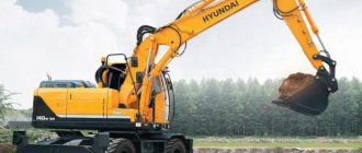
Pneumatic running equipment
provides greater mobility: when relocating from object to object, the excavator can move under its own power or on a rigid hitch behind the tractor (in this case, the drive of the drive wheels and the hydraulic cylinder for controlling the rotation of the front wheels must be turned off). Since the rigidity of pneumatic wheeled running equipment is low, during operation it is necessary to use outriggers to unload the wheel to increase the support contour.
According to their purpose, single-bucket excavators are divided into universal and special.
Universal excavators
are equipped with several types of replaceable working equipment, and special ones are equipped with only one type of such equipment.
Shift worker
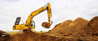
The equipment of single-bucket excavators is designed to perform various excavation works. A straight shovel is used to develop soil located above the excavator parking level; during the digging process, the bucket moves upward from the excavator.
straight shovel
(Fig. 1) is widely used on hydraulic excavators of the 4th - 6th size groups and on mechanically driven excavators. It is used to develop soils of category I - III in the temperature range from -40 to +40 ° C
Fig.1. Hydraulic straight shovel excavator
1 — running trolley; 2 - counterweight; 3 — power plant; 4 — cabin; 5, 8, 9 — hydraulic cylinders of the boom, bucket and handle; 6 - boom; 7 — handle; 10 - ladle; 11 - platform.
The main elements of the working equipment are the boom 6, the handle 7, the bucket 10 and the hydraulic cylinders: lifting the boom 5, turning the handle 9 and turning the bucket 8. Both rotary and fixed buckets can be installed on the excavator. Rotary ones significantly expand the capabilities of the excavator, providing, in addition to soil development, face planning. If a fixed bucket is installed, hydraulic cylinder 8 serves to open the bottom of the bucket when unloading soil.
Backhoe
(Fig. 2) is used to develop soil located below the parking level, while the bucket moves upward towards the excavator.
The backhoe is the main working equipment for hydraulic excavators of the 2nd - 5th size groups. An excavator with a backhoe is designed to develop soils of categories I - III and pre-loosened frozen and strong soils below the excavator parking level and to perform loading and unloading operations in the temperature range from -40 to +40 C.
When working with a backhoe, large digging forces are realized, since the resistance of the soil is perceived not only by the mass of the working equipment, but also by the mass of the entire machine. In addition, the filling of the bucket and the accuracy of unloading have been improved due to its rotation relative to the handle; it is possible to use a wide range of elongated booms and handles and profile buckets for cleaning ditches, channels, etc.
In terms of design, a hydraulically driven backhoe is produced in several varieties, but its main assembly elements (Fig. 2) are a monoblock (L-shaped) or composite boom 6, a handle 8, a backhoe bucket 10 and hydraulic cylinders 11, 7, 9 for boom lifting and turning handle and bucket.
Fig.2. Hydraulic excavator with backhoe
1 — running trolley; 2 - rotating platform; 3 — power plant; 4 — exhaust gas pipe; 5 — cabin; 6 - boom; 7, 9, 11 — hydraulic cylinders of the handle, bucket and boom; 8 — handle; 10 - ladle.
The backhoe boom is welded from alloy steel sheet. It is hinged in the eyes of the turntable, to which hydraulic cylinders 11 for lifting the boom are also connected. The hydraulic cylinder rods are pivotally connected to the boom; when the rods extend, the angle of inclination of the boom relative to the platform changes.
The handle is hinged at the head of the boom. In its rear part, the rod of the hydraulic cylinder 7 for turning the handle is hinged. On the other hand, the hydraulic cylinder is connected to the boom. Extending or retracting the hydraulic cylinder rod ensures that the handle rotates clockwise or counterclockwise relative to the boom. In the front part of the handle, a bucket 10 is hinged, which can be freely rotated using a hydraulic cylinder 9. To increase the angle of rotation of the bucket, the hydraulic cylinder is connected to it by a special articulated multi-link.
The backhoe is equipped with replaceable buckets of various shapes and capacities. Backhoe buckets are most often made of a welded structure without an opening bottom. The upper belt of the bucket is reinforced. In the area of the cutting edge of the front wall, pockets are welded for installing teeth, the number of which depends on the width of the bucket and the type of work for which they are intended. Often, teeth are installed on the side walls, mainly when excavating soil in trenches. These teeth cut the walls of the trench, preventing the bucket from jamming in it. The front wall in the lower part has perforations to remove water when developing waterlogged soils.
When installing a composite boom on excavators, the main and its extension parts are hingedly connected to each other, but to prevent them from rotating relative to each other, an additional rod is installed between them. The rod has several fixed positions, which allows, if necessary, to change the angle between the main and extension parts of the boom.
The soil is developed by rotating the handle relative to the boom or by rotating the bucket relative to the handle.
The backhoe of an excavator with a mechanical (cable) drive (Fig. 3) is somewhat different from the backhoe of an excavator with a hydraulic drive.
Fig.3. Crawler excavator of the 3rd size group with a mechanical drive and “backhoe” working equipment
1 — running device; 2 - rotating platform; 3 - racks; 4, 6 — ropes; 5 — block racks; 7 — handle; 8 — reaction rods; 9 — backhoe bucket; 10 - traction rope.
The bucket 9 (Fig. 3) is fixedly attached to the handle 7, which is achieved by installing reaction rods 8 between the rear wall of the bucket and the handle. The working movements of the bucket are ensured by changing the lengths of the traction 10 and lifting 6 pulley blocks.
Dragline
(Fig. 4) is intended for developing soils mainly below the excavator parking level. Thanks to the extended lattice boom, the dragline can operate over a large digging radius, so it is used when digging large pits, digging canals in irrigation construction and performing loading and unloading operations on bulk materials. This is the only type of working equipment that is mounted exclusively on mechanically driven excavators.
Fig.4. Dragline diagram
1 - aiming; 2 - rope; 3 - block; 4 - rope; 5 - boom; 6 - block; 7 - rope; 8 — dragline bucket; 9 - rope.
The working equipment includes a lattice type boom, a dragline bucket 8, traction 9 and lifting 7 ropes. The lifting rope goes around the head block 6 of the boom and is wound onto the drum of the lifting winch. The traction rope is guided by a roller device (guide) 1 and wound onto the drum of the traction winch. The bucket is suspended from the traction and lifting ropes using chains, and a spacer is installed between the branches of the lifting chains to ensure free movement of the bucket during unloading. In order to unload the bucket, it is tipped over, loosening the unloading rope.
Grab
(Fig. 5) are used for digging pits, trenches, wells and performing loading and unloading operations. Grabs used on hydraulically driven excavators have a rigid suspension. This allows you to create the necessary pressure forces during cutting and effectively develop dense soils.
Fig.5. Grab working equipment
1 - base part of the boom; 2 - traction; 3 — hydraulic cylinder of the handle; 4 — boom head; 5 — handle; 6 — rotating head; 7 - frame; 8 - slider; 9 — thrust; 10 — bucket jaw; 11 — bucket teeth; 12 - axles.
To attach the grab, use the base 1 and the head part 4 of the boom, connected by a rod 2, and the handle 5 of the backhoe. The grab bucket consists of two jaws 10 with teeth 11 and two rods 9. The bucket suspension mechanism includes a frame 7, a rotating head 6, a hydraulic cylinder located inside the frame, and a slider 8. The width of the bucket jaws depends on the conditions of use. Depending on the conditions of rotation in plan, the grab bucket can be attached to the handle in three ways: non-rotating, part-rotating and full-rotating. With any type of connection, the bucket can swing in the longitudinal and transverse directions.
When digging, the initial position of the jaws of the grab bucket is open. The necessary pressure force is created by hydraulic cylinders 3 for controlling the handle. The jaws are closed by a hydraulic cylinder located inside the frame. The rotating head allows the bucket to rotate 180 degrees in a horizontal plane, which increases the operational capabilities of the equipment.
When digging deep (up to 30 m) wells, grab equipment on a pressure rod is used, designed for excavators of the 5th and 6th size groups.
When equipping an excavator with a mechanical drive with a grab, an elongated lattice boom is mounted on it (Fig. 6). The jaws of the bucket are closed with a traction rope, and the height is changed with a lifting rope.
Fig.6. Mechanical drive grab diagram
1, 2 — drums; 3 - traction rope; 4 - lifting rope; 5 - boom; 6 — thrust of the bucket jaws; 7 — grab; 8 — guy.
The disadvantage of rope-controlled grab equipment is that the density of the developed soil depends on its mass, so their main area of application is loading and unloading of bulk materials.
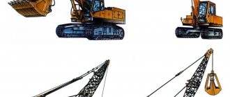
Rice. 7. Replacement working equipment for single-bucket excavators:
a-straight shovel; b-backhoe; c-dragline, g - grab; d - pile driver; e - lifting crane; g - plow; e - soil ripper
Additionally, drilling, piling, crane and other types of equipment can be installed.
By suspension type
working equipment (Fig. there are excavators with flexible elements (mainly ropes) for holding and actuating working equipment (
flexible suspension
) and with rigid elements - mainly hydraulic cylinders (
rigid suspension
).
Rice. 8. Classification of excavators according to the type of suspension of working equipment:
a - with flexible suspension; b - with rigid suspension 16
The design features of the working bodies are determined by their purpose. For their main purpose, working bodies of bucket, grab and loosening types are used, however it should be noted that excavators, being the most universal of all construction machines, have more than forty types of replaceable working equipment.
Based on the ability to rotate the platform, excavators are divided into fully rotating and semi-rotating. On full-rotary excavators, the horizontal rotation of the working equipment is not limited. Partial-rotary excavators are produced as mounted working equipment on a wheeled tractor, so the turning angle of the turning column is limited and amounts to °. To expand production capabilities, the production of full-rotary excavators with a rotary column has now been mastered abroad.
All single-bucket excavators, with the exception of part-rotary ones, regardless of the type of working equipment and type of suspension, have the same structural base (Fig. 9), including a rotating platform 5, a power unit 2, a slewing bearing 6, a running gear 8, a counterweight 1, an operator's cabin 3, working equipment 4, 7 and mechanisms of movement and rotation.
Fig.9. The basic part of a single-bucket excavator and the main types of replaceable working equipment
1 - counterweight; 2 — power plant; 3 — cabin; 4, 7 — exhaust gas pipe; 5 — rotating platform; 6 — rotating support; 8 — running device
The choice of the type of excavator, its model and the type of working equipment is made based on soil and climatic conditions, volumes and timing of work, parameters of earthworks, soil transportation distance and a number of other factors.
The main points when choosing an excavator are also: choosing a rational work scheme; selection of rational technological parameters of the face; rational use of interacting machines (excavators and dump trucks).
The type of working equipment is specified depending on the nature of the work (Table 1.1).
Table 1.1.
Application areas of replaceable working equipment for single-bucket excavators
For example, crawler excavators are recommended for use in concentrated volumes of excavation work when frequent relocations are not required; when working on soft soils; when developing rocky soils, where pneumatic tires quickly fail.
It is advisable to use pneumatic wheeled excavators on soils with high load-bearing capacity and on dispersed volumes of work, as well as in urban environments where frequent relocation of machines under their own power is required.
It is advisable to use excavators on a special automobile-type chassis for dispersed work (construction of roads, power line supports, pipelines, etc.).
It is advisable to use excavators with attached working equipment on pneumatic wheeled tractors in off-road conditions and at dispersed sites.
Lecture No. 2. Bucket (trench) excavators. Bulldozers.
Multi-bucket excavators, or trench excavators as they are also called, are earth-moving machines that perform all operations of the technological cycle (excavation of soil, transportation to the surface and unloading into a dump or vehicle) simultaneously.
They are self-propelled digging machines of continuous action, which, during their forward movement, tear off a longitudinal excavation behind themselves - a trench of a certain depth and width. Unlike single-bucket trenchers, they constantly move during operation and separate the soil from the massif using a group of buckets or scrapers continuously moving along a closed circuit and at the same time evacuate it away from the trench into a dump or into vehicles using a dumping device. Thus, the productivity of trench excavators, constantly moving during operation and separating soil from the massif using a group of buckets or scrapers continuously moving along a closed loop, is 2-2.5 times higher than that of single-bucket machines, with higher quality of work and less energy consumption per 1m3 of developed soil. Moreover, trench excavators are able to effectively develop both unfrozen and frozen soils. The types and parameters of trench excavators are determined by GOST. The main parameter is the depth of the trenches being torn off.
Together with other types of machines and auxiliary equipment, continuous excavators form technological complexes designed to perform various types of work in the construction of oil and gas pipelines, irrigation and drainage canals, installation of drainage systems, closed pressure conduits, extraction and processing of non-metallic building materials, construction of underground cable communication lines and power transmission lines, other communications.
Trench excavators are classified according to the following main characteristics:
— by type of working body
— chain (ETC) and rotary (ETR);
— according to the method of connecting working equipment to the base tractor
— with mounted and semi-trailer working equipment;
— according to the type of chassis of the base tractor
- for tracked and pneumatic wheels
— by drive type
- with mechanical, hydraulic, electric and combined drive.
The working body of chain excavators (Fig. 1.) is a single-row or double-row free-sagging endless chain 5, encircling the inclined frame 7 and carrying buckets or scrapers 6.
Fig 1. Diagram of a chain trench excavator
The working body of bucket wheel excavators (Fig. 2.) is a rigid rotor (wheel) 12 with buckets or scrapers 11, rotating on rollers 8 of frame 9.
Fig 2. Diagram of a rotary trench excavator
The width of the rectangular trenches to be torn off depends on the width of the bucket or scraper and the location of the cutting elements on them.
The same basic tractor can be equipped with interchangeable working bodies with different widths and numbers of buckets (scrapers) for digging trenches with different profile parameters. To obtain a trapezoidal profile, the working parts of a chain and rotary trench excavator are equipped with active and passive slope formers.
Active slope formers of double-chain trench excavators (Figure 1, a) are inclined chains 8 with transverse cutters that perform a reciprocating movement.
Passive slope formers of rotary machines are made in the form of two inclined replaceable knives 13 (Figure 2, a), rigidly fixed to the sides of the rotor frame. Slope formers are used when working in unfrozen soils with low bearing capacity.
To develop frozen soils, chain excavators are equipped with special replaceable working parts. Buckets of rotary excavators when developing frozen soils are equipped with special replaceable teeth reinforced with carbide wear-resistant plates. Digging of frozen soils is carried out at reduced speeds of the tractor and working tool, so the productivity of the excavator is reduced by 3-5 times.
During operation, the chain or rotor moves in the plane of movement of the tractor. The separation of soil from the massif and the filling of the working body with it is carried out as a result of the communication of two combined digging movements to the chain or rotor: the main one - translational relative to the frame (for the chain) or rotational around its axis (for the rotor) and the feed movement - translational in the direction of the machine. The main movement contributes to the separation of the soil layer and is directed tangentially to the digging trajectory. The feed movement regulates the thickness of the soil layer to be separated and is directed perpendicularly (normally) to the tangent. The ratio of the speeds of these movements determines the trajectory of movement of the cutting elements of the working body in the longitudinal-vertical plane, which is an inclined straight line for chain excavators (Figure 1, b) and a trachoid for rotary excavators (Figure 2, c).
The thickness of the chips separated by the chain working element is almost constant over the entire face height. The rotary working body separates chips of variable thickness, reaching a maximum value at the level of the rotor axis of rotation. The speed of movement of the working body and the feed speed (movement of the machine) are selected in such a way that, regardless of the depth of the trenches, 100% filling of the buckets is ensured. The operating speed of excavators when digging trenches is infinitely adjustable over a wide range depending on working conditions, physical and mechanical properties of soils and is 5-800 m/h for chain machines and 10-500 m/h for rotary machines. The speed of movement of the working body is largely determined by the method of unloading the buckets of rotary excavators and the dynamic loads acting on the chain of chain excavators. The speed of the working body of chain machines does not exceed 2.4 m/s. The working parts of modern trench excavators have several speeds, and lower speeds are used when digging trenches in heavy thawed and frozen soils. Both types of machines use a gravitational method of unloading under the influence of the soil’s own weight.
Unloading of soil separated from the massif and raised from the trench is carried out by double-chain excavators onto a transverse dump belt conveyor 3 (Fig. 1, a) when the buckets b or scrapers are rotated relative to the drive sprockets of 4 chains. The evacuation of soil raised by scrapers to the surface on both sides of the trench in single-chain excavators is carried out by two augers 9 (Fig. 1, c) of a screw dump conveyor, driven into rotation by the chain of the working element, or by a scraper conveyor. In rotary excavators (Fig. 2, a), soil from buckets 11 is unloaded when they reach the upper extreme position above the transverse dump belt conveyor 7 located inside the rotor 12. The front bottom shield 6 prevents the premature pouring of soil from the buckets into the internal cavity of the rotor when they are lifted. Belt conveyors of chain and rotary excavators throw soil to the right or left side parallel to the trench into a dump or into vehicles (Figure 1, a) and (Figure 2, c). Typically, conveyors have a curved shape, which, combined with a fairly high belt speed (3.5...5 m/s), provides the required lifting height and soil throw distance.
The depth of the trench to be torn off in a chain and rotary excavator is regulated by a hydraulic lifting mechanism, which also transfers the working body from the transport position to the working position and vice versa. The working body of the chain excavator is connected to the hydraulic cylinders 1 (Fig. 1, c) of the lifting mechanism by a lever system 2 and is driven into the ground by them, held in a given position and forced out of the ground.
The working body of the rotary excavator is suspended on plate chains 4 and 5 (Fig. 2, a) of the lifting mechanism and is buried in the ground to a given floor level by the action of its own gravity, and is held in a given position and forcedly deepened by hydraulic cylinders 2 and 3. Independent forced lifting and lowering both ends of the working body make it possible to deepen the rotor and remove it from the trench with the excavator stationary and to carry out work in cramped urban conditions characterized by the presence of a dense network of roads, underground communications, etc. The rear part of the working body of the rotary excavator is in a suspended or suspended state when digging. rests on a pneumatic wheel. A cleaning device 10 is installed behind the rotor to clear the bottom of the trench from crumbling soil.
As for the designation, alphanumeric indexing is adopted for continuous excavators. The letter part of the index characterizes the type of working body: ETR - rotary type working body; ETC is a chain-type working body. The first two digits reflect the digging depth, dm, the third is the serial number of the model; for rotary boom excavators, the first three digits are the bucket capacity, l, the fourth is the serial number of the model; for cross-digging excavators, the first two digits are the bucket capacity, l, the third is the model number. When modernizing, letters are added after the numbers in the order of the Russian alphabet.
For example, the index ETR-252A means: rotary trench excavator with a digging depth of up to 25 dm, second model, first modernization.
The main directions for further improvement of continuous excavators are increasing their operational characteristics (productivity and reliability), expanding their versatility and scope of application.
Productivity, as one of the most important operational characteristics, can be increased by increasing the unit power of power plants for driving working equipment and improving the working processes of development and soil transportation.
Over the past five years, the power of continuous excavators has increased by an average of 20%, and for certain categories (ditch excavators) - by 30-40%.
Improving work processes involves a complex impact on the soil with working bodies of intensifying action, the use of an inertial method of unloading buckets, and the use of the soil collapse effect. The adoption of these measures leads not only to an increase in productivity, but also to a decrease in specific application rates.
The reliability of continuous excavators is increased through the use of modern components and materials, more advanced design solutions, as well as a high level of their unification.
Expanding the versatility and scope of continuous excavators is achieved by using various types of replaceable working equipment (for example, for the development of frozen soils, excavation of wide or narrow trenches, etc.).
When designing and operating continuous excavators, a distinction is made between technical productivity for each soil category and technical productivity averaged across soil categories.
The technical productivity of continuous excavators for soils of one group Pt, m3/h is
Fri = vxF
vx — working speed of the excavator, m3/h;
F is the cross-sectional area of the excavation, m2.
When determining the technical productivity averaged across soil categories, the share of soil of each category in the total output of machines and the productivity for each category are taken into account.
Bulldozers.
Bulldozers are attachments to a basic crawler or pneumatic wheeled tractor (two-axle wheeled tractor), including a blade with knives, a pushing device in the form of bars or a frame, and a blade control system. Modern bulldozers are structurally similar machines, the basic tractors and attachments of which are widely unified.
The most common bulldozers are those with a fixed blade, those with a rotating blade, bulldozers-rippers, and bulldozers-loaders.
Bulldozers with fixed blades come with rigid (Fig. 1, a) and articulated (Fig. 1, b) push bars.
The bulldozer of the first type is equipped with a blade 1, to which two push bars 7 are rigidly welded, enclosing the base tractor 8 from the outside. The bars are hinged on a transverse beam 6, bolted to the tractor frame. A subframe 5 is also attached to it at the front, to which one double-acting hydraulic cylinder 3 is hinged through the supporting frame 2. Two high-pressure hoses 4 are connected to the hydraulic cylinder, which connect it to the tractor hydraulic system. It consists of a hydraulic pump, hydraulic distributor, hydraulic tank and hydraulic lines. By applying the oil pressure developed by the hydraulic pump to one cavity of the hydraulic cylinder, the bulldozer blade is raised, and lowered into the other. The blade in the soil cutting zone is equipped with removable knives 9.
The bulldozer of the second type includes rectangular push bars 7, which on one side are hinged with the help of harness joints 18 to the tractor bogies 16, and on the other - by universal joints - to the blade 1.
To maintain a certain position and cut the soil with minimal energy consumption, the blade is held on one side by a hydraulic brace 19, on the other by a rigid rod. The hydraulic brace is connected to the tractor hydraulic system and skews the blade in the transverse plane. The bulldozer is equipped with two hydraulic cylinders 3 lifting and lowering, which are also connected to the hydraulic drive of the tractor.
Using hydraulic lifting and lowering cylinders 3, the blade is installed in the lower 7, working II, transport III and intermediate positions.
A tractor, tractor or special chassis can be used as the base machine. The tractor engine, through the clutch 11 or torque converter, drives the gearbox 13 and rear axle 14. The sprockets 15 transmit rotation from the engine to the tracks 17, which move the entire machine forward or backward.
| Due to its large volume, this material is placed on several pages: 1 |
Carrying out work with a dragline excavator or grab
The dragline bucket container is mounted on an extended boom.
Filling with rock occurs when the bucket part is pulled back to the boom. After filling, the container is finally lifted and transferred to the unloading location. Emptying is done by loosening the draft ropes. Soil development using a dragline is carried out when constructing large pits or excavations with a depth of up to 16-20 m, constructing an embankment and similar work. The advantages of dragline machines are the impressive depth of lowering the boom, a working radius of up to 10 m and the ability to operate in areas with a constant influx of groundwater with the effective development of flooded areas.
Dragline work is carried out using end or side trenches. The organization of work and arrangement of penetrations is similar to excavation manipulations of equipment with a backhoe. Most often, the cut layers are unloaded into an organized dump, sometimes into dump trucks with subsequent removal. In certain areas, frontal or side penetrations are available.
A grab is a specialized type of bucket container with two wide blades and a rack (or rope) drive system responsible for the forced closure of the blades. Used for excavating narrow and deep areas below the groundwater level. The grab is hung on an excavator boom to excavate spaces with vertical sides. A system of forced opening of the blades holding the raised contents is responsible for emptying the bucket.
The forced lowering of the stand and the immersion of the bucket part into the rock due to its high dead weight makes it possible to use a grab bucket to develop layers of almost any density, including areas completely hidden under water. The capacity of the bucket part of the grab is 0.35-2.5 m3.
Soil development with excavators
Excavators are classified as earth-moving machines.
The following classification of excavators has been adopted: single-bucket excavators of cyclic and continuous action. The greatest use is made of single-bucket construction excavators (EC) , which carry out about 45% of the total volume of earthworks. The main parameter of the EO is the bucket capacity, m3. Main technological parameters: digging depth (height), maximum digging radius, loading height. Excavators of eight size groups are used in construction, with a bucket capacity of 0.15–4.0 m3. The most widespread are excavators of the 4th and 5th groups (bucket capacity 0.65 and 1 m3).
Most single-bucket construction excavators are versatile machines that can be equipped with various types of interchangeable working equipment. A modern hydraulic excavator can be equipped with more than ten types of working equipment, which significantly expand its technological capabilities.
The process of developing soil with an excavator with any type of working equipment consists of operations alternating in a certain sequence in one cycle: cutting the soil and filling the bucket, lifting the bucket with soil, turning the excavator around its axis to the unloading site, unloading the soil from the bucket, turning the excavator back, lowering the bucket and returning it to its original position.
The use of replaceable working equipment makes it possible to mechanize processes such as cleaning the bottom of excavations, crushing and removing oversized objects and boulders, finishing the surface of slopes of earthen structures, the bottom of excavations, layer-by-layer soil compaction in cramped conditions when installing backfills, loosening frozen and difficult-to-develop soil.
The most common types of working equipment are forward shovels, backhoes, draglines and grabs (Fig. 1).
The maximum dimensions of excavations that can be made by a single-bucket excavator from one parking lot depend on its operating parameters. The main operating parameters of single-bucket excavators when developing excavations are: the maximum possible digging (cutting) depth, the largest and smallest digging radii at the excavator parking level; unloading radius, unloading height.
Soil development with single-bucket excavators is carried out positionally.
The area in which the excavator operates at a given position is called the face. It includes the site on which the excavator is located, part of the soil mass being mined from one parking lot, and the site on which transport is installed for loading or a soil dump is located. Upon completion of excavation of the soil in a given face, the excavator moves to a new position.
Rice. 1. Diagrams of operating parameters of a single-bucket excavator and face profiles: a – straight shovel with hydraulic drive; b – backhoe with hydraulic drive; c – grab; g – dragline
The excavator and vehicles must be located in the face in such a way that the average angle of rotation of the excavator from the place where the bucket is filled to the place where it is unloaded is minimal, since up to 70% of the working time of the excavator cycle can be spent on the boom rotation time.
An excavator with working equipment with a straight shovel (Fig. 1, a) is used to develop soils located above the excavator parking level, mainly with loading onto vehicles.
The excavation process is carried out using frontal and side faces. In a frontal face, the excavator develops the soil in front of itself and loads it onto vehicles that are delivered to the excavator along the bottom of the face. Depending on the width of the penetration, frontal faces are divided into narrow (the width of the penetration is less than 1.5 times the size of the optimal cutting radius Ro; Ro = 0.9Rmax), normal [width (1.5...1.9)Ro] and widened [width (2 …2.5)Ro]. Due to the fact that in order to deliver a vehicle for loading into the excavation under development, it is necessary to arrange a ramp with a slope of no more than 12, the volume of excavation work and the size of the construction site increases.
An excavator with a backhoe (Fig. 1, b) is intended for digging trenches and pits located below the level of its parking lot. Vehicles for loading soil are located at the same level as the excavator. This can significantly reduce the labor intensity of excavation work.
The dragline excavator (Fig. 1, d) develops the soil below the level of its parking lot. Since the dragline bucket is flexibly suspended, it can be effectively used when developing channels and trenches in cohesive soils with unloading into a dump.
The excavator-grab (Fig. 1, c) is used for digging wells, narrow deep pits, trenches and other structures, especially in areas below the groundwater level.
Continuous excavators (EN) are divided into longitudinal, transverse, and radial excavators. As a means of comprehensive mechanization of technological processes for excavation work in construction, longitudinal excavators are most widely used. These include multi-bucket chain and rotary trenchers, chain scrapers, rotary bucketless (milling) excavators, drainage excavators, and ditch excavators. These machines are less versatile than single-bucket excavators. A rational area of application of EN is the construction of trenches up to 4 m deep with a top excavation width of up to 2 m. The possibility of using EN is significantly influenced by cramped conditions and the type of soil being mined. The main parameter of EN is the digging depth. Main technological parameters: width of the trench being developed at the top and bottom.
Chain excavators are used for digging trenches for cables, sewer pipelines, communication lines, etc., with a depth of up to 6 m and a width of up to 2 m. The technological diagram of soil development using a continuous chain excavator ETC-252 is shown in Fig. 2.
Rice. 2. Technological diagram of soil development when constructing a trench using a continuous excavator ETC-252
Rotary excavators are widely used for digging trenches for gas and oil pipelines with a depth of up to 2.5 m and a width of up to 2.6 m.
A rotary trench excavator (Fig. 3) consists of a tractor, a working body in the form of a rotor with buckets and a conveyor. Cutting the soil and lifting it out of the trench is carried out by rotor buckets; From the buckets, the soil is poured onto a short transverse belt conveyor, which delivers the soil to a dump or to vehicles. A bucket wheel excavator creates a rectangular trench with vertical walls. To obtain a trapezoidal cross-section of the trench, its walls are cut off with two lateral inclined cutters. In some designs, an oscillating rotor is made for this purpose. The productivity of a rotary trench excavator (with the same trench dimensions) is 2 times greater than that of a chain excavator and 5–6 times greater than that of a single-bucket excavator.
Rice. 3. Trench rotary excavator : 1 – engine; 2 and 3 – mechanism for lifting the main frame with the rotor; 4 – drive chain; 5 – transverse conveyor; 6 – rotor bucket; 7 – main frame; 8 – support trolley; 9 – stripping knife
Selection of equipment taking into account the main development features and rock types
Single-bucket equipment can be used in all types of rock, including rocky soils and areas with high water flow and a constant supply of groundwater.
Soil development with multi-bucket excavators can be carried out in soils from categories I to IV inclusive. In fact, safe operation can only be carried out in areas of categories I-III that do not have large fractions exceeding 0.2 of the width of the bucket part. Manipulations in areas of category IV are possible only in homogeneous layers.
Initially, the type of machine is selected after studying all the parameters: the characteristics of the excavation, the category of the material being cut, the presence or possible influx of groundwater and the need to use replaceable devices. If several models are suitable for performing one type of manipulation, it is preferable to excavate soil in trenches and other spaces using an excavator backhoe type bucket part .
Determining the required volume of a bucket container is carried out according to the principle of maximum filling with minimal time expenditure. The maximum load directly depends on the type of material being processed, the complexity of the cutting and the depth of the work. The maximum capacity is calculated taking into account the depth of the excavation, the type of equipment and the group of rocks.
The final choice should include not only an analysis of the soil category, but also taking into account climatic conditions and terrain. For example, the use of single-bucket mechanisms with a “straight shovel” bucket capacity is suitable for rocky areas with large slopes and complex terrain, and the development of group 2 soil , including fine and medium gravel, is optimal for development an excavator with a “backhoe” bucket capacity.
Soil development using earthmoving and transport machines
Earthmoving and transport machines (EMTs) are machines that simultaneously perform layer-by-layer separation from the massif and move soil to the place of laying or to a dump. Such machines include bulldozers, scrapers, motor graders, and grader-elevators. With their help, embankments are erected, excavations and pits are made, the subgrade is profiled, areas are planned and other types of work are performed.
The ZTM work process includes digging soil, transporting and unloading it, and is performed while the machine is moving. Depending on the design of the working bodies, a distinction is made between bucket (scrapers) and blade (bulldozers, graders and elevator graders) earthmoving and transport machines. Earth-moving vehicles are produced as self-propelled, as well as trailed and semi-trailer ones.
Based on the power of their power plants, earthmoving and transport machines are divided into low power (up to 100 kW), medium (100–200) and large (over 200).
The efficiency of the ETM largely depends on the terrain, climatic conditions, physical and mechanical properties and soil conditions: strength, humidity, stickiness, shear resistance.
Earth-moving machines are distinguished by high maneuverability and mobility, simplicity of design and maintenance, including preparation for work. The continuity of their cycle is ensured by the fact that digging, transport and planning equipment can be combined in one unit. Thanks to this, earthmoving and transport machines in combination can perform most of the main and auxiliary earthworks in all branches of construction.
Bulldozers are designed for layer-by-layer development of soil of categories I–IV and its movement during the construction and preliminary profiling of soil embankments; leveling the soil poured into piles and shafts; rough leveling and planning of surfaces; digging trenches for foundations and communications. They are used for vertical surfaces of surfaces, development of recesses and pits, cutting terraces on slopes, backfilling trenches, pits and cavities of building foundations, as well as for clearing areas of snow, stones, bushes, stumps, small trees, construction waste, etc.
Bulldozers with special equipment are used to push scrapers while loading them.
Bulldozer attachments for a basic crawler include a blade with blades, a pushing device in the form of bars or a frame, and a blade control system. The tractors of modern bulldozers are equipped with a diesel engine with an increased reserve of power and torque, a mechanical or hydromechanical (dynamic or volumetric) chassis transmission with a power shift gearbox and a hydraulic control system for the bulldozer blade. The latter allows you to move the blade in a vertical plane, move it to a floating position, warp it in the transverse plane, change the cutting angle, and in bulldozers with a rotating blade, rotate it in plan at an angle of up to 25° in both directions. Modern bulldozers are structurally similar machines, the basic tractors and attachments of which are unified. The main parameter of bulldozers is the traction class of the base tractor (tractor).
Currently, bulldozers are produced with various design solutions for the blade.
The universal blade is used for leveling work in soils with disturbed structure.
The spherical blade is used to develop soft and medium-hard soils.
The shape of the blade, curved in plan, is intended for oblique cutting of soils, which reduces cutting resistance and can increase the length of the blade by 10–12%. Due to the protruding ends of the blade, the volume of soil moved increases by 20–25% compared to a straight blade.
A blade with loosening side teeth is used to develop hard rocky soils with high-power bulldozers. The teeth are extended by hydraulic cylinders below the knives by 20–30 cm. The scoop blade has side shields that reduce soil loss during movement, and a protruding part of the knife for better cutting into the ground. It is used to develop loosely cohesive soils when they are moved over long distances.
In addition to the indicated types of dumps, additional types of replaceable working equipment are being introduced into production for finishing embankment slopes, loosening soil, removing bushes, etc. Their use significantly increases the versatility of bulldozers.
Depending on the operating conditions, power and type of tractor, crawler bulldozers operate at speeds of 2.4–6.0 km/h, on wheeled tractors – 3.5–8.0, and move soil at speeds of 4–8 and 6–8, respectively. 12 km/h (idle speed – 10–12 and 20–25 km/h).
When digging, the cutting part of the blade is buried in the ground and the bulldozer simultaneously moves forward. Modern bulldozers accumulate the maximum possible volume of the drag prism in a section 6–10 m long. The economically feasible range of soil movement does not exceed 60–80 m for tracked vehicles and 100–140 m for pneumatic-wheeled vehicles. The soil cut from the face accumulates in front of the dump, forming a soil prism, which is called a drawing prism. After this, the dump is dug out and a bulldozer moves the soil to the placement site. Next, the bulldozer levels the soil prism with a previously slightly raised blade. You can level the soil by driving the machine forward or in reverse. When transporting soil, part of it is lost. Losses, depending on the distance of movement, can reach up to 30% or more of the volume of the drawing prism.
The basic diagrams of cutting and moving soil with a bulldozer are shown in Fig. 4.
Rice. 4. Scheme of cutting and moving soil with a bulldozer: a – longitudinal when cutting downhill on a horizontal section using the trench method; b – longitudinal when cutting downhill on a horizontal section in a layer-by-layer manner; 1 – embankment; 2 – notch
The scraper is designed for layer-by-layer development of soil, transportation and layer-by-layer placement of it into an earthen structure or dump with leveling. When moving along the poured layer of soil, the scraper simultaneously partially compacts it.
Scrapers are classified according to the following criteria:
- according to the geometric capacity of the bucket: 1.5; 3.0; 6.0; 10.0; 15.0; 25 m3;
- by mode of transportation: trailed, semi-trailered, self-propelled;
- by unloading method: with free, semi-forced and forced unloading.
Scrapers are used in road, industrial and hydraulic construction for the construction of embankments from lateral reserves, excavations with the movement of soil into the embankment, the construction of dams, and excavation of pits. They can work on a wide variety of soils, except swampy ones. On wet clays and black soils, soils stick to the walls of the scraper bucket and clog it. Loose sand also does not fill the bucket well and is difficult to unload from it. It is most effective to use scrapers on sandy loams and loams, since these soils fill the bucket well.
Scrapers can be used to develop soil up to category IV inclusive. To increase the efficiency of scrapers with soils of categories III–IV, they are pre-loosened.
When operating the scraper on heavy soils, the traction force of one tractor or single-axle wheeled tractor may not be sufficient to cut chips and fill the bucket. In such cases, a pusher is used - a crawler tractor or a two-axle wheeled tractor. The pusher rests with the pushing device on the rear buffer of the scraper and, together with the tractor, creates the traction force necessary to fill the scraper bucket. Scraper feeders and elevators increase the filling level of the scraper bucket and provide a more uniform load to the scraper and reduce the required traction force.
The use of trailed scrapers is advisable for moving soil over a distance of 100 to 300 m.
Self-propelled scrapers are effective with soil movement ranges from 300 to 5000 m or more.
Free unloading does not ensure good emptying of the bucket of sticky and wet soils and is used only in small-capacity machines.
The most reliable, although somewhat more energy-intensive, is forced unloading.
Scraper movement diagrams are shown in Fig. 5.
Rice. 5. Scraper movement patterns: a – ellipse; b – spiral; c – “eight”; g – “zigzag”; d – shuttle-transverse; e – shuttle-longitudinal
Motor graders are intended mainly for carrying out planning work and profiling the subgrade during the construction of roads and railways. The working part of the machine is the blade. Change the position of the blade in the horizontal plane by rotating the turntable.
Leveling the surface of the developed area or profiling the roadway is carried out in several passes with different blade settings, and consists of the operations of cutting out the soil and moving it along the blade while moving the motor grader. To expand the scope of application and increase the time of use of the machine throughout the year, motor graders are equipped with replaceable working equipment for various purposes: plow and rotary snow blowers, grader-elevator, road milling machine.
Experience with motor graders shows that the number of passes to cut a trough is usually 6–8.
A grader-elevator is an earth-moving and transport machine used for layer-by-layer development of soil using a working tool in the form of a knife or scoop and moving it with a belt conveyor or thrower to a dump or vehicles. Grader elevators provide high productivity. They are used for the construction of low embankments of roads and railways from side ditches mainly in flat areas, the development of excavations with the movement of excavated soil into a dump, the construction of semi-embankments on slopes with a transverse slope of up to 12° and the digging of small canals for irrigation of land.
The high productivity of grader elevators is greatly facilitated by the division of the functions of cutting and moving soil between the working bodies - knives and conveyors.
It is advisable to use them only in linear work with long sections where continuous operation can be ensured.
Safe operation techniques during excavation
- Do not install the machine in a work area with a pronounced slope. For installation, choose only level areas - this will prevent the risk of overturning.
- When performing work on the bucket part with a straight shovel in a face with high walls, it is necessary to promptly remove the resulting peaks.
- In weak and moving ground areas, the path of movement of equipment is strengthened by shields laid on the ground.
- Development of Group IV sections with an excavator is carried out using additional equipment - the installation of specialized devices will prevent premature wear of the mechanisms.
- If the work area becomes very wet, production should be stopped until the surface dries.
Before starting the production process, it is necessary to carefully examine the areas for the appearance of cornices and overhangs.
Construction site preparation
Before the immediate start of excavation activities at the work site, it is advisable to organize a travel route, if there is none. The problem of removing trees on the site should also be approached responsibly. Non-fruitful trunks more than 5-6 years old can be uprooted only with the permission of the local administration. After planting the tree, it is necessary to fill the resulting hole with coarse sand to the level of the foundation.
In the process of arranging a construction site, it will be useful to record the areas where the fertile layer is removed. In the future, this information will be useful for carrying out agricultural work near the house. Before excavating a pit with an excavator, it is also recommended to organize sites or containers for collecting the removed fertile soil. Since it may be useful in the future, it should be placed in places where there is no construction waste or other household waste. While the work is being carried out, a temporary fence with an opening only for working equipment is installed in front of the house on the entrance side.