Safety devices and devices
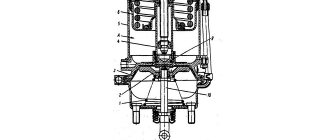
To regulate the uniform movement of the shoes from the pulley, the electromagnet is again placed in the closed position with the release nut 4. Next, the lock nut 7 is loosened and by rotating the adjusting screw 8, a uniform gap is achieved between both shoes and the pulley.
The size of the gap (0.4 -1.0 mm) is determined with a feeler gauge or by rocking levers 9. After completing the adjustment, screw 8 is fixed with lock nut 7. The installation length of the closing spring is measured with a ruler with a division value of 1 mm with the electromagnet armature open. The calculated value of the braking torque of the brake is given in the factory instructions for each crane mechanism. This moment corresponds to a certain length of the closing spring when the brake is closed, given in the instructions for the brake. If the length of the spring differs from the installation length, then hold nut 3 with a key against rotation and rotate rod 1 by the square shank in one direction or another, increasing or decreasing the length of the spring.
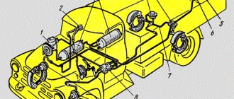
Rice. 9. Adjustment of brakes with electrohydraulic drive: a - general view; b - intended parameters
Brakes driven by TKTG are adjusted (Fig. 9, a) in the same sequence as TKT brakes. The differences are that instead of the stroke of the electromagnet, the stroke of the pusher rod is adjusted with nuts 1, and the length of the spring is set with nut 2 on the spring rod. The uniform removal of the shoes from the brake pulley is ensured by screw 3. The pusher rod 4 should not reach the bottom stop when the blocks are placed on the pulley. In this case, it is necessary to ensure the minimum distance h, which is obtained by subtracting the installation stroke Rus given in table from the maximum distance H (Fig. 9, b), measured with the rod raised to failure. 6.
The operator must carefully inspect and adjust the crane brakes every day! Electric overhead cranes are equipped with means of collective protection against electric shock. These taps use four power systems for electrical devices: a three- or four-wire three-phase alternating current network with a voltage of 220/380 V; two-wire DC network; two-wire single-phase alternating current network with a voltage of 220 V; a two-wire single-phase alternating current network with a voltage of 12-36 V. The electrical equipment of cranes belongs to the category of installations with voltages up to 1000 V. The operation of such installations is associated with a serious danger of electric shock.
The voltage a person is exposed to depends on the type of contact with live parts: single-phase and two-phase. With single-phase touch, a person comes into direct contact with parts of electrical equipment that are normally or accidentally energized. The degree of injury to a person from such a contact depends on the quality of the insulation of the network wires, its length, and also on whether the electrical network has a grounded or insulated neutral. When a single-phase touch occurs in a network with a grounded neutral, a person comes under phase voltage, which is 1.73 times less than linear. The amount of current flowing through a person's body will depend on the phase voltage, the resistance of the person's body and the insulation of the floor on which the person is standing. With a two-phase touch, a person is simultaneously under voltage from two different phases. In this case, the strength of the current depends on the line voltage and resistance of the human body.
What it is
During hoisting operations performed by a drawworks, a device such as a band brake is used in gas and oil wells. It looks like an elastic steel strip that goes around the brake pulley. The design of the device is very simple and consists of a braking band with friction pads mounted on the frame, a lever on the crankshaft and a pneumatic cylinder. The last element begins to work at a time when the maximum force of the driller is more than 250 N.
The tape communicates with the leading edge fixed to the frame. The other end is passed through the rod and goes to the brake lever. When the belt is tensioned, it is attracted to the moving pulley and braking occurs. Some designs involve the use of internal tapes. In this case, when braking, the belt, on the contrary, unclenches. When the brake of the lifting mechanism is completely open, the braking process is performed by pressing a special spring, which is pulled onto the lever with the pedal.
How overhead crane brakes work
Overhead cranes are complex equipment. Their device has many systems that regulate operation. One of the most important is the brake.
The brake system is responsible for stopping the moving mechanisms of the equipment and holding the load suspended, as well as its smooth lowering and preventing involuntary movements of the machine.
The brake system regulates the operation of various parts and components of the crane
How does the braking process occur and why do overhead cranes need brakes?
The principle of operation of the braking system is quite simple. In order to stop the movement of the mechanism, it is necessary to convert the kinetic energy that it loses during movements into thermal energy. The easiest way to do this is through friction, so in the first brakes a special pad was pressed against the wheel, stopping it. Modern systems make it possible not only to stop the mechanism, but also to collect all the lost energy into storage devices or batteries for further use.
The importance of this mechanism is due, among other things, to the fact that the overhead hoisting crane, for all its massiveness and large dimensions, has good mobility and a high frequency of operation cycles. This means that in a certain unit of time the crane is capable of performing a large number of operations, and therefore the start-braking speed must be quite high. Therefore, it is so important that all elements of the braking system work smoothly and properly.
What brakes are used in overhead cranes?
Bridge cranes are most often equipped with a shoe or disc-shoe braking system. A shoe brake system is a brake in which the shoes are pressed against the wheel. In lifting equipment, such a device is necessary to stop and hold mechanism shafts when the electric motor is not running.
terms of Use
During operation, carry out regular technical inspection and maintenance of your equipment. Especially if the loads of this kind are intense and the load being held is heavy. It is also necessary to test the brakes of the mechanism. During testing, the hoist brake must be checked for operation at least three times.
Various systems have wear parts, regular replacement of which will ensure trouble-free operation of your enterprise. Also, to increase safety, the hoist provides space for a second additional brake.
To order this product, you just need to call our office in Moscow at the numbers listed in the contacts!
Leave a request
Products
Shoe brakes with an electrohydraulic drive are designed for installation on the mechanisms of hoisting and transport machines, winches, conveyors and other mechanisms with a horizontal brake pulley axis.
Main technical data and characteristics:
| Parameter name | Brake size | ||||
| Calculated braking torque, Nm | 100 | 300 | 800 | 1500 | 2500 |
| Brake pulley diameter, mm | 160 | 200 | 300 | 400 | 500 |
| Power consumption, W | 160 | 160 | 200 | 240 | 240 |
| Type of current | Variable, frequency 50 Hz | ||||
| Voltage, V | 220/380 | ||||
| Pusher type | TE-30 | TE-30 | TE-50 | TE-80 | TE-80 |
| Nominal force on the pusher rod, N, not less | 300 | 300 | 500 | 800 | 800 |
| Stroke of the pusher rod, mm | 32 (50) | 32 (50) | 65 | 80 | 80 |
| Time to apply blocks, s no more | 0.2 | 0.2 | 0.35 | 0.4 | 0.4 |
| Brake weight, kg, no more | 21.5 | 30 | 55 | 95 | 130 |
We supply separate components for brakes:
pads, brake band, electric hydraulic pushers, frames without pushers.
Crane brakes
Shoe brakes of the TKG series are designed to complete lifting, transport and some other types of equipment. They are used to brake and fix moving parts of mechanisms, shafts, when the drive is turned off. The brakes of this series consist of an electro-hydraulic pusher, a pad, a rod with a spring, a lever system, and adjusting screws. They are mounted on a stand. In the brakes of the new modification of types TKG-160-1 and TKG-200-1, due to the use of an electro-hydraulic pusher TE-30 RD with a built-in check valve and damping device, a smooth increase in the braking torque M from (0.2 0.8)M 3[0] in an adjustable time range from 2 to 8 s. The use of these brakes in the mechanism of movement and rotation of cranes in normal technological mode allows them to be adjusted to the calculated braking torque, ensuring braking of the crane without jolts, sudden decelerations and disruption of the running wheels, which increases the reliability and safety of operation of cranes operating in the open air and exposed to wind loads. TE-30 pushers are installed on TKG-200 shoe brakes, TE-50M pushers on TKG-300, TE-80M pushers on TKG-400, TKG-500. The pusher should not be used for work in explosive environments, as well as in environments containing caustic vapors and gases that destroy metals, insulation and rubber. When installed on mechanisms operating outdoors, the brakes are protected by a casing from precipitation and solar radiation. Safety requirements according to GOST 12.2.007.0-75 and GOST 12.2.007.1-75. Brakes of the TKG and TKTG types with electrohydraulic pushers are used in mechanisms of all mode groups with climatic modifications recommended for northern, temperate, and tropical regions, which is associated with the peculiarity of the negative impact of sudden temperature fluctuations on the transformer oil used in electric hydraulic pushers. Brakes equipped with electromagnets are used at various temperature differences, while TKT type brakes are recommended for use in mechanisms with a mode group no higher than 4M.
TECHNICAL CHARACTERISTICS TKG
| brake size | TKG-160 | TKG-200 | TKG-300 | TKG-400 | TKG-500 |
| braking torque | 100 | 300 | 600 | 1200 | 2500 |
| brake pulley diameter, mm | 160 | 200 | 300 | 400 | 500 |
| power consumption, W | 160 | 160 | 200 | 240 | 240 |
| pusher type | TE-20 | TE-30 | TE-50 | TE-80 | TE-80 |
| rated force on the electrohydraulic pusher rod, N | 300 | 300 | 500 | 800 | 800 |
| stroke of the electrohydraulic pusher rod, mm | 32 (50) | 32 (50) | 50 | 50 (65) | 80 |
| blocking time, s | 0,2 | 0,2 | 0,35 | 0,4 | 0,4 |
| brake weight, kg | 21,5 | 30 | 55 | 95 | 150 |
| overall dimensions (L*B*H), mm | 490*202*415 | 608*202*421 | 772*232*550 | 895*232*600 | 1160*232*735 |
A brake with an electrohydraulic pusher consists of the following main parts: an electrohydraulic pusher and a mechanical part. The principle of operation of brakes of this type is as follows: when the electrohydraulic pusher is turned off, under the action of compressed springs, the levers press the pads to the surface of the brake pulley; the rod of the electrohydraulic pusher is in the lower position; when the electro-hydraulic pusher is turned on, its piston pushes up the rod, which decompresses the springs; the levers, freed from the action of the springs, diverge, releasing the pulley.
OVERALL DIMENSIONS OF BRAKES
| Brake size | L, mm | H, mm | A, mm | h, mm |
| TKG-160 | 490 | 415 | 200 | 144 |
| TKG-200 | 608 | 421 | 350 | 170 |
| TKG-300 | 772 | 550 | 500 | 240 |
| TKG-400 | 895 | 600 | 340 | 300 |
| TKG-500 | 1160 | 735 | 410 | 400 |
TECHNICAL CHARACTERISTICS TKT
| brake size | TKT-100 | TKT-200/100 | TKT-200 | TKG-300/200 |
| pulley diameter, mm | 100 | 200 | 200 | 300 |
| electromagnet type | MO-100 | MO-100 | MO-200 | MO-200 |
| type of current | variable | variable | variable | variable |
| operating voltage, V | 110; 220 | 110; 220 | 110; 220 | 110; 220 |
| weight, kg | 12 | 25 | 36 | 70 |
Shoe brakes have a spring closure, automatically open when the drive is turned on and are installed, as a rule, on high-speed shafts of mechanisms equipped with brake pulleys. By changing the installation length of the spring, you can change the braking torque. Features of the brakes are: * guaranteed interchangeability; * high braking torque, independent of the direction of rotation and ensured by the optimal geometry of the lever mechanism; * ease of adjustment; * the ability to replace the brake pad without disassembling the brake. Electromagnetic brake The drive consists of the following main parts: an electromagnet and a mechanical part. When the electromagnet is turned off, under the action of the compressed main spring, the levers press the pads to the surface of the brake pulley. When the electromagnet is turned on, its armature, pressing against the core, moves the end of the rod, which compresses the main spring. The levers, freed from the action of the spring, diverge, releasing the pulley.
Brake TKG-300 for the load lifting mechanism of the gantry crane KKS-10, KK-12.5
Vendor code:
- Description
- Characteristics
- Ask a Question
- Delivery
Brake TKG-300 for gantry crane KKS-10, KK-12.5
Brake TKG-300 for gantry crane KKS-10, KK-12.5
is a device that regulates the movement of various executive bodies, bringing them to a complete stop, reducing speed or holding them stationary.
These functions are carried out by fixing the shafts
of the structure when the drive is not working. Such brake units are installed in a vertical position, and the pulley axis and mounting base in their composition are located horizontally.
Specifications
In accordance with the rules provided for by GOST 15150-69
, such devices belong to the
U2
.
They are designed for operation in temperate climates in a non-explosive environment at a minimum temperature of -40 degrees and a maximum of +40. The units are connected to an electrical network with a voltage of 380V and a frequency of 50Hz. Typically, such brakes are used in enclosed spaces, but they can also be used in an open area under a special canopy. However, it is first necessary to protect the structure with a casing
, which prevents the entry of moisture, dust and reduces the negative effects of sunlight.
As indicated in the product designation, shoe brake TKG-300 for gantry cranes KKS-10, KK-12.5
equipped with a hydraulic pusher.
Its main function is to convert electrical energy into mechanical linear motion, during which the braking devices are activated. The only vulnerability of hydraulic pushers is that they are filled with liquid
.
Therefore, it is necessary to constantly monitor the tightness of the housing and eliminate leaks in a timely manner. This model of brakes is most widely used because it has a number of undoubted advantages
:
- Easy to operate;
- No lateral loads on the roller;
- Increased reliability.
In addition to gantry truck cranes, stackers, belt conveyors and cargo winches
.
Over time, the brake can wear out, as indicated by several visible signs: the formation of fatigue cracks, wear of shafts, pins and axles, a reduction in rim thickness by 50% of its original size, and other problems. If malfunctions are detected, it is necessary to carry out timely repairs
, since it is extremely unsafe to operate a failed shoe brake.
The device has a calculated braking torque of 600 Nm and a brake pulley diameter of 300 mm. The weight of the entire structure as a whole may vary depending on what type of hydraulic pusher it is equipped with.
Electrohydraulic pushers type TE-30(50.80)-SU-U2, TE-30(50.80)-SU-HL2 are interchangeable with pushers type TE-30(50.80), TE-30(50.80)M produced by the Tomsk Machine-Building Plant named after. Vakhrushev (TU 16-530.192-80) and type TE-30(50.80)-2M produced by Bendersky (TU MD 29.18.37370499.001-99).
Hydraulic pusher type TE
| Standard size | Weight, kg |
| Hydraulic pusher TE-30 (analogous to TE 16, TE 25) | 12 |
| Hydraulic pusher TE-50 | 13 |
| Hydraulic pusher TE-80 | 14 |
The main point that makes crane hydraulic pushers vulnerable is the presence of liquid in their design. During operation, it is necessary to ensure the tightness of the housing, the correct installation position and compliance with the external temperature conditions. It is the condition of the liquid that is checked first if problems arise in the operation of the electric hydraulic pusher. Only a specialist can correctly qualify the problem and send the failed hydraulic drive for repair or consider it to require replacement.
vote
Article rating