Machine structure
The operating principle of a crane is based on the physics of simple mechanisms. The simplest version of the crane is a stick placed on a fulcrum in such a way that the free ends have different lengths. Now if you hang a load on a short lever, it will take less effort to lift it. The most common design is one that uses, in addition to levers, a system of blocks.
A do-it-yourself crane is an indisputable assistant in small-scale construction. When constructing a private house, the use of bulky industrial cranes is not required. The height of the houses rarely exceeds 2 floors, and the weight of the lifted load is 200 kilograms.
Crane diagram
Although there are many variations of lifting mechanisms, a classic crane consists of the following parts:
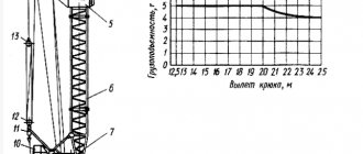
- An arrow with a block attached to its end. Depending on its length, the height to which the load can be lifted is determined.
- Platform. The boom and counterweight are attached to it. It is the main part of the crane and is subject to significant loads. Therefore, when manufacturing a platform, it is important to pay special attention to its strength.
- Counterweight. Serves for crane stability. Defines the maximum load weight that the crane can lift. Stackable counterweight options are available to provide maximum stability.
- A guy wire connecting the boom and the counterweight. Allows you to adjust the tilt of the boom and move the load in both vertical and horizontal planes.
- Winch with cable. It is the lifting mechanism itself. The power of the winch determines how much weight the crane can lift.
- Stand with a rotating mechanism. It is necessary to turn the crane to the sides.
- The support cross, which is the base of the crane. Sets the stability of the entire structure. When manufacturing it, you should also pay attention to its strength.
Add a cab and counterweight
1. Take the previously set aside blank for cabin G
and
counterweight
N. Mark the center of the hole in the middle of the width at one of its ends (Fig. 1a).
Using a 25mm Forstner drill bit, make a hole using a drill press. Then use a band saw to cut a 10 mm wide bevel, sand it and saw off the cabin from the workpiece. Mill 2mm chamfers on the edges of the hole and the outer ribs of the cab. Finish sand the part.
Apply a little glue to the G cabin and glue it to the B/C mast close to the D/E/F boom, securing it with a clamp.
2. Before attaching the G
to mast
B/C
, insert the boom between the side parts of mast
B
and a piece of threaded rod into the holes of both parts.
Then glue the cabin to the side parts B (Fig. 1
and
photo G ).
Now temporarily remove the boom from the mast.
H according to the specified dimensions
.
Mill chamfers on its edges (Fig. 1)
and finally sand the part.
Glue the counterweight to the D/E/F
, aligning it in the middle of the width with a space of 13mm from the rear end.
Homemade mini crane
Regardless of the height of the structure, the weight of concrete blocks always remains the same. To make work easier during construction, you can make your own crane. With a small carrying capacity of about 200 kg, it is not difficult to assemble. The equipment is intended for domestic use and weighs 200-300 kg. This is a convenient model, easy to assemble and disassemble. Small dimensions allow you to transport equipment in a pickup truck. Prepared drawings will help simplify the assembly process; they include the following information:
- The basis of the structure consists of a cargo winch and supports. For the first, a gearbox with a worm base is used. With its help it is possible to create a manual drive. Then assembling the boom winch will become easier. Construction supports serve as a base for external screw parts.
- Winches need a base. It is made from an electric motor rotor. All parts must match each other in size, so they are carefully measured with a ruler. You won’t be able to make the base yourself, because this requires special equipment.
- The platform is equipped with wheels, this will simplify the movement of the crane along the surface.
- To ensure that the crane stands stable and does not lose balance, the boom is set to zero level.
- An arrow is made from a pipe with a diameter of up to 8 cm. Its acceptable height is 5 m. A profile of 2 corners is installed in the base.
- A turning mechanism is created from a car hub. He will be responsible for the rotation and lifting of the boom. The hub can be used from any cargo transport.
- Simple bricks are suitable as a counterweight.
- The crane is installed on a frame from an old machine or on a caterpillar track.
- Since the equipment operates at low speed, the turning mechanism and winch do not need a brake.
To make a garage crane, you will need: a hand winch, a cross pipe and racks on wheels. Pipe fasteners are welded at the top of the racks. The manual winch is mounted on a vertical stand. You can buy a ready-made winch or make it yourself. For self-production, a drum with cables is used, which is mounted on a structure made of pipes. A large sprocket with a chain is attached to the drum, and a small one is attached to the electric drive. If the winch is manual, the shaft with the drum is supplemented with a handle. To move the cable, rollers are required; they are mounted on the beam.
The result is a compact device that will not take up much space and will be easy to disassemble. The finished crane will be able to move loads of up to 800 kg.
Design made from improvised materials for work in the garage
Such a homemade lift is especially needed by those who repair cars for removing
or installing heavy components and assemblies of the car.
The crane is assembled from a frame, which is welded from a pipe, an iron profile, and angles. It is easier to install them crosswise, since this arrangement provides greater stability of the crane. Wheels are attached to the edges for easy movement around the garage.
The height of modern houses is becoming larger, but the weight of concrete blocks is not decreasing. For this reason, even for domestic purposes, it would be a good idea to make a crane with your own hands. This design, naturally, will not have a large load capacity, approximately 200 kg. Of course, this is probably not the limit, but it’s better not to experiment. This crane is a completely prefabricated structure that weighs from 200 to 300 kg, so self-assembly of such a crane will not cause difficulties. In addition, this crane is very convenient to transport; it fits well in a Chinese pickup truck.
The cargo winch can be made from a worm gear with an electric drive of 600 W, while the boom winch can be made from a manual drive organized using the same gearbox.
You can use construction supports as a basis for outriggers on screw stops. To make drums for winches, you can use rotors from electric motors, and they should be selected according to size.
The mobile platform must be equipped with wheels that were previously on the conveyor trolley. This makes it possible to easily move the crane from one position to another; all that needs to be done is to remove the outriggers.
Removal and installation of these supports will take approximately five minutes. For this reason, the design can be considered quite mobile. However, there is a drawback: to move the crane you need to lower the boom to zero level, otherwise the crane may overturn due to imbalance.
The do-it-yourself crane has a five-meter boom made from a Ø 7.5 cm pipe and a square profile at the very base, made from a pair of corners. In addition, the crane has a portal to lift the boom, and a rotating mechanism, which is based on a hub from a truck.
As a counterweight, you can use a frame from a non-working machine complete with four caterpillar tracks, or just bricks. The winch does not include a brake, since the need to use it is a big question.
The turning mechanism also does not have a brake, since the crane is not designed to operate at high speeds, and therefore the inertial forces are too small.
The thinnest metal used for this tap is approximately 3 mm. The outrigger and the base are, for the most part, made of a rectangular pipe, with dimensions 85 by 50 and 85 by 55. A 200 channel channel is used to make the base of the tower. The hook cage is equipped with a powerful bearing, which means that the rotation of the hook does not depend on the pulley. At the same time, during rotation, overlapping or twisting of the track is eliminated.
The length of the stop screws is 40 cm. This is the reason that the installation of the crane can be carried out even on extremely uneven surfaces.
Now about the wheels, not everything is so smooth here. We are talking about a small flaw. The essence of the problem is that when using a crane with the described wheels on loose soil, the wheels burrow into the ground while moving, and if the soil is hard, then there are no problems. The described design can be considered disposable, which means that after you have completed the necessary work, it should be disassembled for metal or until next time. It is for this reason that this design has little load capacity and is not durable.
A crane of this type can be manufactured in approximately three days, taking into account the fact that all the necessary components are prepared. The production of gearboxes was made from the first items that came to hand. The gearboxes have the following gear ratios: 1 to 30 and 1 to 35.
A three-phase motor is connected to a single-phase network. It has a shaft output of 600 W and capacitors with a capacity of 80 microfarads. The weight of all installations, if not taking into account counterweights, will be approximately 250 kg, with a relatively low cost. The bulk of the components used are borrowed from other designs; you only have to worry about purchasing cables and bearings.
After you make a crane with your own hands, you can easily lift 150 -200 kg, which is quite impressive considering that it is not intended for industrial scale.
A simpler version of the tap:
Throughout the long history of its existence, man has more than once been faced with the task of lifting and moving heavy objects in space. For example, the familiar Egyptian pyramids consist of massive stone blocks that no one can lift. Therefore, one of the greatest achievements of mankind is the invention of the lifting crane, which made it possible to significantly simplify the task of moving heavy loads and speed up the construction of houses and other objects.
Lift
Modern lifts are divided by type into:
- Foot. They are capable of lifting heavy loads weighing up to 2 tons to a height of 8 meters.
- Telescopic. Their advantages include: light weight and compactness. These devices are capable of lifting loads to a working height of up to 150 kg.
They, in turn, are divided into:
- self-propelled;
- non-self-propelled.
When choosing a lift, it is worth considering several factors: their dimensions, load capacity, scope of application.
To make a lift yourself, prepare materials and a preliminary drawing. To build it we will need:
- a winch, which can be made from a drum and a cable;
- pipes;
- electric drive
The advantages of construction hoists include:
- maneuverability;
- high load capacity;
- safety;
- ease of use.
Make a chassis
Mark the centers of the holes for the wheel axles in chassis A. Using a clamp, pressing the chassis against the drill table stop, alternately drill holes 38 mm deep.
1. For chassis A
, cabin
G
and counterweight
H
, cut out a workpiece measuring 38x159x305 mm. (We chose walnut.) Using a longitudinal cut, separate a 38 mm wide block from one edge of the workpiece and set it aside to later make a cabin and counterweight out of it. Saw the rest of the workpiece to the dimensions of chassis A, indicated in the “List of Materials”.
2. Mark chassis A
front and rear bevels
(Fig. 1).
File them with a band saw and sand them smooth.
Then insert a 9 mm drill bit into the drill chuck, fix the stop at a distance of 13 mm from the drilling axis and make holes for the wheel axles on both sides of the chassis (photo A)
. Finish sand the part.
Lift for laying aerated concrete blocks
Abroad, during the construction of private houses, cranes and various lifts are often used. This way construction goes faster, which means the “box” is cheaper, because It is more profitable to use small-scale mechanization tools than to hire laborers. Our developer relies on himself and often builds a house “with one helmet.” Therefore, the urgent question is how not to physically overstrain yourself when laying a wall from aerated concrete blocks weighing 35-40 kg.
An interesting option is the unusual homemade “assistant” of the FORUMHOUSE user with the nickname Krestik. First, let's show what he took as a basis.
German mini crane with retractable central post
A special feature of the lift is the original folding “arm-boom”, with the help of which the crane, moving on wheels, can reach two opposite walls.
I am building a house myself and, in order to be able to lay aerated concrete blocks, I built a lift according to the above model. The crane was made completely collapsible, except for the base. I didn’t measure the maximum load on the hook, but it easily lifts me (weighing 95 kg).
Technical characteristics of the lift:
- width – 2200 mm;
- height – 4200 mm;
- boom radius – 4200 mm;
- load capacity of electric hoist – up to 800 kg;
- total weight of the crane with ballast is approximately 650 kg;
- lift weight without ballast – about 300 kg;
- The maximum lifting height of the masonry block is 3500 mm.
The working height of lifting blocks is adjustable in two ranges. The first is 1750 mm. The second is 3.5 m, for which the structure is raised, sliding upward along the supporting “legs” using a hydraulic jack lined with spacers made of GB blocks.
To make the lift, the user needed:
- swivel wheels;
- profile pipes for the mast, “legs” and boom with a section of 12x12 cm, 12x6 cm, wall 6 mm;
- pipe-jibs – 63x3 mm;
- powerful gate hinges;
- The boom rotating mechanism is made of ST45 steel and “205” bearings.
During operation, the design was modified. For example, the user laid the cable for the winch in a corrugated pipe and extended the cable for the control panel.
The design has a number of shortcomings that I would like to correct. For example, I’m thinking about making wireless control, replacing the gate hinges with bearings. Increase the number of “joints” in the boom at the same reach. Instead of a temporary counterweight - bags of sand concrete, pour concrete ballast.
An important nuance: in order for the lift to move around a construction site or, for example, on a concrete slab on the second floor, you need to keep the workplace clean, because GB fragments and debris interfere with the relocation of the tap.
The design of the unusual lift attracted the interest of portal users.
With such a lift, I think, as they do in Germany, you need to make masonry from blocks larger than standard ones. The length and height are 2-3 times greater than a regular GB. The crane has enough lifting capacity, and the laying speed will increase significantly.
According to Krestik, he heard that someone on the portal had already tried to order blocks of 1x0.4x0.6 m format from a gas silicate manufacturer. But it turned out that this was not profitable for the plant, because it is necessary to reconfigure the line for the production of GB, but for the sake of a small volume (for an ordinary private house) they will not do this.
I'm wondering: is the work on site easier when using a crane? What work can be done with it and what cannot?
There is no need to install scaffolding when laying GB walls. The lift can be assembled and disassembled. I poured the concrete lintels over the windows the old fashioned way, from buckets, because... The volume is small, and it’s easier to do it with one assistant.
The overall result: the mini-crane turned out to be successful, and with some modifications to its design, the lift can be put into small-scale production.
Glue the mast and boom
Fasten the side parts B with double-sided tape, mark the centers and drill holes through both parts.
1. For side parts B
and progavok
C
, cut out two blanks measuring 19x38x660 mm.
(We used maple.) From each piece, make one side piece and one spacer. Attach a Forstner drill with a diameter of 25 mm into the chuck of the drilling station and make five holes in each side part (Fig. 2, photo B)
2. To assemble the mast, prepare a pair of clamping strips measuring 19x57x610 mm. (We used scrap MDF.) Cover one side of the clamping strips with masking tape to prevent them from sticking to the parts. Place tape on one side of each side piece B
, limiting the location of spacers
C
in accordance with
Fig.
2. (The tape is thick enough to keep the clamping bars from moving and to easily remove excess glue.) Glue the mast parts together
(photos C
and
D ).
Glue spacers C to one side piece B. Apply glue and place the second mast side piece on top.
Secure the parts between the leveling bars and then press them vertically with clamps. The bottom spacer C and both side pieces B must be aligned at the base.
3. Mark on side piece B
mast center 5mm hole for the boom axle
(Fig. 2).
Using a drill press, make a hole by inserting 19mm thick scraps between the mast side pieces to prevent chipping.
Once the glue has dried, remove the clamps and strips, mark a bevel on the top end of the mast and file it with a bandsaw.
4. Make a V/C
upper bevel
(Fig. 2, photo E)
and sand smooth.
Then sand the 3mm fillets on the top corners of side pieces B
and top spacer
C
. Insert an edge cutter into the collet of a router mounted in the table and mill 2 mm wide chamfers along the edges of the holes and the outer ribs of the mast (except for the bottom ones). Finish sand the mast.
5. For making front D
and rear
E
boom spacers, sharpen a workpiece measuring 35x560 mm to a thickness of 6 mm (we took walnut) and saw it into pieces of the specified length.
Using a band saw, make a bevel on the front spacer and a taper on the back (Fig. 3).
Sand the sawed edges.
As with the mast assembly, prepare 19x19x610mm clamping strips and apply masking tape to align spacers D, E between the side pieces F for gluing.
6. For boom side parts F
Take a maple blank measuring 19x35x5 72 mm, saw it lengthwise in half along its thickness and plan both strips.
Glue spacers D, E
between the side parts
F (Fig. 4
and
photo F ).
7. When the glue has dried, make an E
using a drill press, a 2.5mm hole for the cord, a 5mm hole for the axle and another 5mm hole at the front end of the boom
(Figure 4).
Before drilling the front hole, insert
a 6mm thick piece of scrap F Then mark the two tapers, cut them with a band saw and sand them down to the marking lines. Also sand the 3mm rounds on the ends of the boom and rout 2mm chamfers along all the ribs. Finish sand the finished arrow.
terms of Use
To operate lifting mechanisms safely, certain rules must be followed.
Homemade Pioneer crane
These rules apply to any lifting device:
- The load capacity must not be exceeded. A load that is too heavy may damage the device.
- The base must be stable. Homemade lifting devices should be located on a previously prepared hard horizontal surface.
- In bad weather conditions, you should also refrain from working with the crane. Strong winds will throw the crane off balance, and poor visibility may make it difficult to see people under the boom.
- Before operating a crane or lifting device, it is necessary to conduct an external inspection to identify any malfunctions. If malfunctions are detected, operation of the crane is prohibited.
- It should be remembered that when working with the lift, you should not make sudden movements. The load must be lifted smoothly. And most importantly, do not stand under any lifted load.
Blueprints
To make a crane, first of all, draw up a project diagram and drawings of the main components. Consider the manufacture of a manually operated crane structure. It would be possible to make a device powered by electricity, making it possible to move a load using a device on a long cable, as happens in factory designs. But then the complexity of manufacturing units increases, this will entail an increase in the cost of the finished product and an increase in the time for its creation. Therefore, we will focus on making a manual model.
Drafting
To build a house you need a crane. Let's look at how to independently make a miniature crane design for lifting construction loads to a height. It is necessary to manufacture a mobile dismountable device.
First, a design for the manufacture of the apparatus is drawn up and calculated:
- The main part of the structure is the supporting frame. It is installed on wheels or permanently.
- The rotation unit of the unit is fixed to the running frame.
- The boom can be rotated thanks to the creation of electric or manual control.
- The unit can be disassembled into parts for ease of transportation.
- The crane will be stable thanks to the creation of a block of counterweights and steel cable stays.
- The load will be lifted using a block and a winch.
- You need to assemble a crane with your own hands.
Homemade lift and mini-crane: inexpensive and effective
Building a house alone is possible, but difficult. Especially if you have to lay stone walls, lift bricks to the second floor, or “throw” sand and bags of cement onto the ceiling. So as not to overstrain yourself. To save on ordering a crane and, in general, to simplify your task, many FORUMHOUSE users make mini-cranes and hoists. In this article we will talk about two successful designs.
- Automatic lifting and unloading mechanism for bulk materials
- Homemade crane based on an electric hoist for lifting aerated concrete
conclusions
We talked only about a small part of the homemade products for building a house posted on the portal. New items appear every day, and any DIYer can find what he needs. Don’t forget to follow the updates in the profile topics, and you will probably find what you need to independently build a country house!
We recommend going into a truly “hot” topic – Diary of a Self-Builder. Bad advice that tells how, with the help of invention, ingenuity and direct hands, to build a house from aerated concrete without hired workers.
As promised - 3 articles about the best homemade cranes - 1. A lift for bulk materials and 2 mini cranes: do it yourself for an inexpensive price; 2. Mobile crane for laying blocks: do it yourself; 3. DIY mini-crane: overview of options.
Also read the articles:
- Universal folding trestles. Do it yourself The process of making carpentry trestles from “A” to “Z” according to the American model: drawings, parts, necessary tools, 3 options for non-standard use of the trestle.
- Two options for homemade snow blowers from walk-behind tractors: from idea to implementation in metal. Design, necessary parts, tools and stages of creating homemade products.
- How to build a stone house for 350 thousand rubles with your own hands - an anti-crisis proposal. Cheap house project. The main stages of construction, what tools are needed, detailed estimates.
In the video: According to my project: A house from a change house for only 370 thousand rubles.
What characteristics should a garage lift have?
In garage conditions, two types of lifting mechanisms are used. The first type includes a lift that can lift the entire car, and the second type includes a goose-type lift that allows you to move loads around the garage.
Lifts of the first type are stationary devices and the main requirement for them is stability. The car weighs more than a ton and should not have the slightest chance of falling. In order to prevent any accidents, the garage lift must have a reliable stopper.
Homemade goose tap
The goose type lifts are most often used in auto repair shops. It is quite simple to make it from a profile pipe or channel. First, the base is welded on which the rotating mechanism needs to be installed. It is best to make an arrow with an adjustable reach. This will make it possible to move weights in any direction.
How a simple block design works
The pulley system or pulley system has been known to mankind since ancient times. The classic system design consists of pulleys and cable. One pulley is called a block. Depending on the method of fastening, the pulley can be movable or fixed:
- Fixed block. It is attached to the support and plays the role of changing the direction of movement of the rope. Does not provide any gain in strength.
- Movable block. It is located on the side of the load and gives a gain in strength.
The principle of operation of a pulley block is similar to the principle of operation of a lever in the physics of simple mechanisms. The role of the lever in this case is played by the cable itself. In the case of a simple block of two pulleys, the movable pulley divides the rope into 2 parts and in order to lift the load the same distance, a rope twice as long will be required. The work of lifting the load is performed in the same volume. And the effort, due to the fact that the length of the rope has become twice as long, becomes half as much.
If there are more than 2 pulleys in the system, the gain in strength is approximately equal to the number of blocks. In the case of 3 blocks, the effort will be 3 times less, and 4 blocks will require only a quarter of the original effort.
Machine for making dowels
Another story. Machine tools and machine tools are a must-have in the arsenal of any self-builder. If you need to make dowels in industrial quantities for the construction of a wooden house, do not pass by the original machine.
I'm building a log house. I need dowels - 1000 pcs. The price of one dowel is 10 rubles. In total, it turns out that I need to spend 10,000 rubles. to the "pegs". Expensive! I decided to make a machine for making dowels. I looked at different designs on the Internet. That's it, that's not it. The cutter is stationary and the workpiece rotates. This is suitable for making thin rods, but I need dowels with a diameter of 2.5 cm. You can’t stick such a workpiece into a drill. So I made a machine with a rotating cutter. The cross-section of the workpiece for the dowel is 2.6x2.6 cm. If it is birch, then 2.5x2.5 or 2.4x2.4 cm is better. The dowels come out from under the machine with a smooth surface. The length of the dowel is not limited in any way. Made more than 1000 pieces. dowels, 30 cm long.
Note: The user tried 5 methods before settling on this method of making dowels. The rotating cutter option is the best. For production 500 pcs. dowels, taking into account cutting the wood with a circular saw into square blanks and sorting them, takes 10-12 hours.
Watch the video and evaluate the speed of operation of the machine.
Hydraulic garage crane drive
There are several types of hydraulic drive:
- with hydraulic cylinders;
- with hydraulic cylinders and manual winches.
When the operator increases the pressure level in the cylindrical block, the oil fluid acts on the piston part, pushing out the telescopic rod, at which time the boom equipment rises.
Based on the nature of the movement of the output link of the hydraulic power unit, the following types of drives are distinguished:
- Rotational movement. The design of such a mechanism includes a hydraulic motor equipped with a driven link with unlimited rotational movement.
- Forward movement. In this case, a hydraulic cylinder is used with a reciprocating movement of a driven type link (piston rod, plunger).
- Rotary movement. The crane mechanism is equipped with a rotary hydraulic motor, the driven link of which makes a reciprocating movement at an angle of less than 270°.
- Adjustable. In this case, the speed of the output type link can be adjusted by changing the crankshaft speed of the power unit, which activates the high pressure pump.
- With a closed circuit of working fluid circulation. This means that the fuel is returned to the suction hydraulic line of the pump mechanism. This drive is lightweight and provides high rotor speeds without the risk of air getting into the system.
Complex block system how to calculate power gain
If the system is designed in such a way that one simple pulley pulls another simple pulley, then this is already a complex system of blocks. To theoretically calculate the gain in strength, it is necessary to conditionally divide a complex chain hoist into simple ones and multiply the values of the gain from simple chain hoists.
For example, if the system consists of 4 blocks, and the first conditional simple pulley has a gain of 3. It pulls the second simple two-block pulley, also with a gain of 3. The total force that will need to be applied will be 9 times less. It is the 4-block complex chain hoist that is most often used by rescuers.
DIY mini-crane: overview of options
When building a house from aerated concrete, timber, brick, etc. There is often a need to lift a load. For example, you need to “throw” blocks or wooden beams onto the second floor, lift bags of cement, or pour an armored belt. Doing this manually, even with the help of assistants, is not so easy - health is more expensive. Hiring a truck crane or manipulator for a small amount of work is expensive. The solution is to use a mini-crane, which, to reduce the cost of construction, is made by hand.
articles:
- How to make a lift for laying aerated concrete.
- What parts and tools are needed to build a mini crane.
- How to reduce the costs of building a universal lift.
The design of the unusual lift attracted the interest of portal users.
Universal folding trestles, height adjustable
Goats are indispensable when building a house. Cut long pieces.
Plan something long.
Or, build a scaffolding by laying a couple of sawhorse boards to stand on.
Goats have a use everywhere. They are usually made from wood. For example, folding trestles.
Or stationary ones that you don’t mind leaving on the street.
And here is a version of a metal goat with retractable legs, from a portal member with the nickname Mikhail Rivshin.
Or increase or decrease the height, depending on the tasks performed.
Methods for attaching a rope to a lifting mechanism
When creating complex pulley blocks, there are often situations when a cable of the required length for attaching the moving block is not at hand.
Crane for gas blocks
Methods for attaching a cable using general-purpose rigging:
- Using a cord. Using a self-tightening knot, the cord is tied to the main cable. As the load is lifted, the grappling knot moves along the main rope, thereby allowing the height of the load to be increased.
- Using clamps. In the case of using a steel cable, it is not possible to use a cord, so it is necessary to use special clamps.
We create a simple lifting mechanism with our own hands
Construction of a crane is not a quick task and is justified if it is required frequently or the volume of work is large enough. In cases where the load needs to be lifted urgently or this is a one-time operation, you can use improvised means.
To create a simple lifting device you will need a cord and two blocks. One block and the end of the rope are fixed motionless on the support. This will be the highest point to which the load can be lifted. We attach the second block to the load using slings or a hook. We first pull the rope along the block attached to the load, then pass it through the upper block. The gain in power will be 2 times. Using your own weight, you can easily lift a load weighing 100 kilograms to the required height.
DIY mini crane
If you add the ability to move the upper block along a guide, for example along a rail, you can get a do-it-yourself jib crane. It is useful in garage conditions for moving heavy machine parts.
It should be remembered that when working with the lift, you should not make sudden movements. The load must be lifted smoothly. And most importantly, do not stand under any lifted load. The same rule applies to a crane - standing under the arrow is prohibited.
Make a winch
I from 12 mm planks
.
Use double-sided tape to connect them face to face. Mark according to Fig.
5a the centers of the holes and drill them with a 6mm drill bit using a drill press. Mark a bevel on one corner, file it with a band saw and sand it. Then sand the small rounds on the outer corners, separate the pieces and give them a final sanding.
2. Cut out the winch platform J
, making sure that its width corresponds to the total thickness of the
B/C
and both
sides
I. Mill a chamfer along the top front rib (Fig. 5).
Drill mounting holes to attach the base to the side parts of the
mast B. (For screws with a diameter of 4.2 mm, the diameters of the mounting and pilot holes are 4 and 2.8 mm, respectively.)
Through the holes in the sides of winch I, drill 5mm holes for threaded rods through the B/C mast.
3. Attach the sides I
to platform
J (Fig. 5).
Drill holes and screw in screws.
(For screws with a diameter of 3.5 mm, the diameters of the mounting and guide holes are 3.5 and 2.4 mm, respectively.) Insert the B/C
between the sides of the winch and through their holes, drill holes in the side parts B
of
the mast.
Screw in the screws. Now, using a drill press, make 5mm through holes in the mast (photo H).
Place the swivel support in the middle of chassis A, turn the winch and mast sideways to access the bottom flange and mark the centers of the screw holes.
4. With the winch upside down and the mast attached, place it in the middle of the underside of the base J
swivel support, drill guide holes and screw in screws
(Fig. 1).
Then place the winch and mast on chassis
A
and mark the centers of the holes for attaching the swivel support
(photo I).
Remove the mast and winch from the chassis to drill holes for the screws.
5. Take two pieces of 6mm wooden dowel rod, 102mm long, and glue a spool in the middle of each (Figure 5).
When the glue has dried, drill a through hole with a diameter of 2.5 mm in the middle in the coils and dowels.
6. In four wooden button handles, drill an axial hole to a diameter of 6 mm to a depth of 10 mm. How to fix the handles on a drilling machine is described in the “Tip of the Master” below.
How to Safely Hold Round Pieces When Drilling
When trying to drill holes in turned knobs, you are faced with two difficulties: how to hold the spherical part upright on a level table and how to prevent it from rotating when the drill is immersed in the wood. There is an easy way to kill two birds with one stone. Drill a 19x6 mm recess in the cut board. Place a piece of double-sided tape measuring 38x38mm on top of it (photo below left). Align the handle over the center of the recess and press it firmly onto the trim. Now, pressing the scrap against the machine stop, position the drill exactly above the axial hole of the handle and you can start drilling (photo below right). This method also works for wooden balls.
Types of manual taps
All construction cranes are classified into:
- self-propelled;
- stationary;
- tower;
- special purpose.
This equipment is equipped with a boom extension mechanism, a cargo trolley, and a rotating support.
By type of movement they are divided into:
- stationary;
- adjustable;
- self-elevating;
- mobile.
According to the type of control, these devices are electrically driven and manual (mechanical).
This is interesting: The principle of operation and the difference between a crane beam and a hoist - let’s introduce the issue