“A tower crane (English: Tower crane, French: Grue a tour) is a jib-type rotary crane with a boom attached to the top of a vertically located tower.”
A more complete definition of tower cranes is as follows: “Tower cranes… Read more are construction cranes with a boom attached to the top of a vertically mounted tower, the principle of which is to move loads and install building structures through a combination of working movements, such as lifting and lowering the load, changing the angle of departure of the tower crane boom itself or by moving a load-lifting winch along the boom, as well as turning the boom or the entire tower structure with the load, and moving the tower crane itself around the construction site (for mobile cranes).”
Construction tower cranes are used as the main lifting machines for construction, installation and loading and unloading work in civil, industrial and energy construction. In short, tower cranes are called KB cranes.
What is a tower crane
The crane is called a tower crane because the load-bearing support of this cargo vehicle resembles the structure of a tower, all elements of which are made of metal. In addition to lifting, crane equipment can move a load lengthwise and also rotate it around a central axis. This makes it possible to deliver building materials to almost any point where work is taking place.
Scope of application and installation
The assembly of a KB tower crane begins with the installation of a crane rail track. For this purpose, P50/P43 rails are used. After installing the chassis, the tower is brought into a vertical position. For this purpose, cranes of medium class lifting capacity are used. The assembly is completed by mounting the boom, extending the tower part and adjusting the components.
Requirements for organizing and carrying out work on the installation of load-lifting cranes
Related video: Tower crane KB-674A - review
Leave a request to find the best price
Fill out the form below and a manager will call you back and advise you on any questions and select the best price in Russia
Description of the design and parameters of tower cranes Link to main publication
Classification of crane equipment
Tower cranes are classified according to several criteria.
By purpose:
- General use - for the construction of industrial and civil facilities of medium complexity.
- Special application - for solving highly complex problems.
- High-rise cranes capable of working at great heights during the construction of skyscrapers. They are self-lifting, attached and creeping.
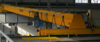
- Crane loaders are often two-post systems (gantry cranes) mounted on rail guides for movement. They are intensively used in large industrial warehouses.
On freedom of movement:
- Stationary type - divided into attached and universal models.
- Mobile – transported by trailer or on a self-propelled basis.
- Self-lifting equipment that is attached to the top of the structure being built.
According to the running mechanism:
- Tracked;
- On pneumatic wheels;
- Rollerblading on a rail track;
- On the chassis;
- Walking cranes;
- Based on cars.
In addition, the designs of modern crane equipment are classic, quick installation and topless.
Taking into account the design of tower cranes and the role of their application, the equipment is grouped into groups. Within these groups, models may have identical assembly units, similar circuit diagrams and standard block modules. This approach greatly simplifies the task of choosing the right unit for the consumer among different manufacturers. It also simplifies the maintenance of crane equipment.
Classification of cranes by method of movement
According to this criterion, the following types of tower cranes are distinguished:
- Stationary. They do not have a running mechanism. Installed in a predetermined location without the possibility of movement. They are used primarily on construction sites. They can be attached or universal. Attachable models are used for lifting loads on high-rise structures.
- Self-elevating. Installed on the building frame.
- Mobile. They can be self-propelled or trailed. They are distinguished by good maneuverability, which makes them in demand in various fields of activity.
How the crane works, its principle of operation
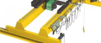
Models of tower cranes produced by modern engineering enterprises have 5 main parts.
Lattice tower. Based on tubes or telescopic with a rotation at the bottom, at the top of the vertical part of the structure. Among the models that are produced nowadays, there is equipment with an expandable or extendable folding tower (with the possibility of dismantling on site) and non-dismountable.
The boom is working. It is a horizontal lifting element made according to the principle of an articulated or beam structure of a suspended or hammer-type type. The materials used are metal profiles, angles or pipes. The booms are equipped with a cargo trolley.
Tower crane structure
Working boom . It is a horizontal lifting element made according to the principle of an articulated or beam structure of a suspended or hammer-type type. The materials used are metal profiles, angles or pipes. The booms are equipped with a cargo trolley.
Bearing support. Holds the entire faucet. It is located at the base of the tower and resists all overturning loads, has increased strength and reliability.
Moving device (chassis) . It is responsible for moving the entire structure of the tower crane and turning it around. It happens with the use of different supporting and moving elements.
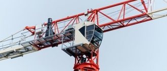
Operator's cabin . It controls all types of mechanisms responsible for the operation of equipment components.
Basic systems
The mechanics of a crane presupposes the presence of three basic systems with the help of which all movements of lifting equipment are possible - these are winches, blocks and pulleys. They allow you to:
- Rotate and move the tower;
- Raising and lowering the boom in the vertical direction;
- Changing the horizontal reach or moving the cargo cart.
To capture the load, a hook clip fixed to a steel cable is used. The cable moves due to the operation of the winch through a block on the cargo trolley, providing lifting to the desired height. The winch is also responsible for moving the trolley itself. The rotation of the structure is carried out due to the rotary support device, which transfers overturning loads and vertical loads to the fixed part of the frame.
Main technical characteristics
Tower-type lifting mechanisms are characterized by the following parameters:
Technical characteristics of the KBM-401PA tower crane with a luffing jib
- Maximum boom reach with tilt and horizontally;
- Minimum reach;
- Maximum possible reach with the maximum permissible load with an inclination and horizontally;
- Maximum permissible load weight at maximum boom radius;
- Maximum level of rise in height;
- Minimum lowering of the load;
- Speed of extension of a loaded boom;
- Speed of lifting weight;
- Empty hook lifting speed;
- Speed of movement across the terrain;
- Rotation frequency around the support tower.
KB-408.21
For example, the KB-408.21 crane has:
- Boom - beam type;
- Tower - rotatable design;
- Possibility of extension - with a loaded hook;
- Chassis type – on rollers on rails;
- Drive control – electric;
- The location of the counterweight is on the rotating platform at the bottom, on the spacer at the top;
- A tower of eight sections.
Tower crane KB-408.21
The technical characteristics of the lifting mechanism are as follows:
- Load capacity (t) at maximum boom extension horizontally – 3, obliquely – 10;
- Reach (m) maximum horizontally – 40, inclined – 35;
- Reach (m) minimum horizontally – 4.5, inclined – 4.2;
- Extension (m) at maximum load horizontally – 16, inclined – 14;
- Lifting height (m) horizontally – 54, inclined – 72.2.
RBC-2.20
The RBK-2.20 crane has the following design:
- Boom - beam type;
- Tower - rotating telescopic;
- Possibility of departure - with a loaded hook;
- Stationary;
- Drive control – electric;
- The counterweight is located on the rotating platform at the bottom, on the spacer at the top.
Tower crane RBC-2.20 - technical data
The technical specifications are as follows:
- Load capacity (t) at maximum horizontal boom extension – 0.7;
- Reach (m) maximum horizontally – 25;
- Reach (m) minimum horizontally – 4.5;
- Extension (m) at maximum load horizontally – 10;
- Lifting height (m) – 18.9.
The lifting capacity of a crane is characterized by the maximum permissible weight of the working load that the crane is designed to lift. The lifting capacity also includes the mass of removable lifting devices (grab, traverse, slings), with the exception of the mass of the hook suspension.
Since tower cranes are made with a variable reach, the crane’s lifting capacity (based on the conditions of structural strength and stability of the crane) is set depending on the reach. The maximum load capacity usually corresponds to the minimum reach.
The load moment M is the product of the load capacity and the corresponding reach. Since the load moment takes into account two main parameters, it is often used as the main generalized parameter of the crane. For many tower cranes, the load moment at various flights is assumed to be constant.
Therefore, by reducing the reach by half, it is possible to increase the load capacity by two times while maintaining a constant load moment.
The lifting height is understood as the vertical distance from the crane parking level to the load-handling element in the upper working position. If there is a lifting boom, the lifting height is set depending on the reach. The characteristics of these cranes indicate either the lifting height for the two extreme reaches: maximum Ht and minimum R2, or are given in the form of a graph depending on the reach. In this case, the crane parking level is understood as the horizontal surface of the base (for example, the paths of movement of cranes on pneumatic wheels or crawler tracks or the surface of the rail heads for rail-mounted cranes), on which the non-rotating part of the crane rests. For self-lifting cranes, in which the supports can be located at different heights, the parking level is determined by the lower support of the crane.
The lowering depth h is the vertical distance from the crane parking level to the load-handling device, which is in the lower working position.
The lifting range!) is the vertical distance between the upper and lower working positions of the load-handling device.
Track K is the horizontal distance between the axes of the rails (for rail-mounted cranes) or the wheels of the chassis (for cranes on pneumatic wheels or crawler tracks).
The base B of a crane is the distance between the axes of the crane supports moving along one common rail (for rail cranes) or located on one side of the crane relative to its longitudinal axis.
The rear clearance is the largest radius of the rotating part of the crane (slewing platform or counterweight console) on the side opposite the boom. The size of the rear clearance for cranes with a rotating tower determines the choice of the distance of the crane runway from the wall of the building being constructed. The distance to ensure safe clearance between the crane and the building for cranes with a rotating tower is taken to be 0.7–1.0 m greater than the rear clearance.
The speed of lifting (lowering) loads is the speed of vertical movement of the working load. If there are multi-speed winches, the crane characteristics indicate the lifting speed at each of the possible winch speeds.
The landing speed vu is the lowest speed of lowering (lifting) the largest working load during its installation or laying.
The rotation speed n is the rotation speed of the rotating part of the crane. The swing speed is determined at the greatest reach with the working load on the hook and is measured in revolutions per minute.
The speed of movement of the crane is the operating speed of movement of the crane along a horizontal path with a working load.
The speed of movement of the trolley vr is the speed of movement of the cargo trolley along a horizontal path with the largest working load.
The rate of change in reach of vry cranes with a luffing jib is the average speed of horizontal movement of the working load when the reach changes from the largest to the smallest. Sometimes, instead of the rate of change in reach, the characteristic indicates the time of change in reach, i.e. the time required to change the reach from the maximum to the smallest when the offset changes under load.
installed power is the total power of the electric motors of all mechanisms installed on the crane. Sometimes the specifications indicate the installed power of operating mechanisms, which includes the power of mechanisms that operate repeatedly during each shift (for example, a cargo winch, a boom or trolley winch, slewing and moving mechanisms for a crane).
Considering that cranes often serve buildings with complex configurations and at the same time move along curved paths, the radius of curvature was introduced into the crane parameters. It represents the smallest radius of curvature of the axis of the inner rail on a curved section of the track. For cranes on pneumatic wheels (Fig. 4, c), the turning radius is used as a parameter, i.e. the smallest radius of the circle described by the outer front wheel of the crane when changing the direction of movement.
The structural mass is the mass of the crane without ballast and counterweight in an unfilled state, that is, without fuel, oil, lubricants and water.
The total mass is the total mass of the crane with ballast and counterweight in a fully charged state.
The maximum wheel pressure is the maximum load transmitted by one running wheel to the crane runway. The design of the crane runway is selected based on the maximum wheel pressure.
The productivity of a crane is either the total living area built with a crane per year (thousand m2/year), or the total mass of goods moved or mounted by a crane per year (t/year). To plan the load of cranes, productivity, measured by the number of cycles per shift, is sometimes used. In this case, a cycle is understood as a set of operations performed by a crane from the beginning of lifting one load to the beginning of lifting the next.
The accompanying documentation for the crane (in particular, its passport) indicates the permissible design wind speed during operation of the crane, as well as the permissible wind area for installing the crane. The wind speed for each area is variable, depending on the height above the earth's surface. The crane's passport indicates the permissible wind speed during operation at a height of 10 m.
For the stability of the crane when not in operation, the maximum wind speed that can occur in the area where the crane is installed is of great importance. According to the maximum wind speed, according to GOST 1451-65 “Cranes. Wind load”, the entire territory of the Soviet Union is divided into wind regions. Since each crane is designed for a certain maximum wind speed, the operation of the crane is only permissible in the corresponding general area or in an area where the maximum wind speeds are lower than the design ones.
The operating mode of a mechanism is understood as a characteristic that takes into account the use of a given mechanism in terms of the frequency of occurrence of maximum loads and time. According to regulatory documentation (in particular, the Rules of Gosgortekhnadzor) there are: light, medium, heavy and very heavy VT modes. The mechanisms of tower cranes operate, as a rule, in light mode, less often in medium mode. These modes are characterized, on the one hand, by the fact that the mechanisms and their elements relatively rarely operate at maximum loads caused by the most unfavorable combination of acting forces from the mass of the load, wind, slope, dynamics; on the other hand, the fact that during a machine shift the mechanism works, as a rule, no more than 25-40% of the time. The more severe the regime, the greater the safety margins the mechanism structures must have.
The operating mode of the crane is determined by the operating mode of the cargo winch, therefore, if the cargo winch on the crane operates in medium mode, and all other mechanisms are in light mode, the crane is considered to be operating in medium mode.
Most of the noted parameters are regulated by GOST 13555-68 “Mobile construction tower cranes. Standard sizes and main parameters" and GOST 14274-69 "Construction tower cranes attached and self-climbing. Basic parameters and dimensions."
—
Parameters are the basic quantities that characterize the crane. A common parameter for all types of lifting machines is lifting capacity.
The lifting capacity of a machine means the weight of the largest working load that it is designed to lift.
The load capacity includes the mass of removable lifting devices and containers; for machines operating with a grab or electromagnet, the mass of these lifting devices is included.
Jib slewing cranes must be capable of lifting the largest working load on the design slope in all positions of the slewing part. The calculated angle of inclination is taken to be an angle whose value for jib cranes (except railway ones) is taken to be at least 3°, for portal cranes - at least 1°.
For railway cranes, the angle of inclination is determined by the amount of excess of one rail over the other on curved sections of the track (Article 32 of the Crane Rules).
For jib cranes, when working on outriggers, the inclination angle can be 1°30”. The design angle of inclination of a crane with tower-boom equipment is determined by the design organization and is indicated in the crane's passport (information and directive letter of the USSR State Technical Supervision Authority dated August 26, 1971).
Parameters for the main types of cranes are established by the following state standards:
GOST 7075-72 “Manual overhead traveling cranes”. The standard applies to overhead cranes with a lifting capacity from 3.2 to 20 t inclusive with manual drive of lifting and moving mechanisms.
GOST 7413-69 “Manual overhead cranes for general purposes.” The standard applies to manual overhead single-girder, single-span general purpose cranes with a lifting capacity from 0.5 to 5 t with manual drive of lifting and moving mechanisms.
GOST 7532-64 “Single-girder overhead cranes with electric hoist. Types. Basic parameters and dimensions." The standard applies to single-girder overhead cranes with a lifting capacity of 1 to 5 t with an electric travel mechanism.
GOST 7890-67 “Single-girder electric suspension cranes for general purposes.” The standard applies to overhead electric single-girder cranes for general purposes with a lifting capacity from 0.25 to 5.0 t, inclusive, controlled from the floor, operated indoors or under a canopy at an ambient temperature from -10 to +40 ° C.
GOST 7464-55 “General-purpose electric overhead cranes with a lifting capacity from 5 to 50 tf for light duty operation. Basic parameters and dimensions." The standard applies to general-purpose electric overhead cranes with one and two hooks, three-phase and direct current, light duty, with a lifting capacity from 5 to 5 t inclusive.
GOST 3332-54 “General-purpose electric overhead cranes with a lifting capacity from 5 to 50 t, medium and heavy duty. Basic parameters and dimensions." The standard applies to general-purpose electric overhead cranes with one and two hooks, three-phase and direct current, medium (duty duty = 25%) and heavy (duty duty = 40%) operating modes, with a lifting capacity from 5 to 5 t inclusive.
GOST 6711-70 “General purpose electric overhead cranes with lifting capacity from 80 to 320 t. Basic parameters and dimensions."
GOST 12613-67 “Electric overhead cranes for stripping ingots. Main parameters". The standard applies to electric overhead cranes for stripping ingots with a lifting capacity of 32/12.5 to 80/32 tf, with a pushing force from 200 to 400 tf, DC, without an independent auxiliary lifting mechanism.
GOST 12612-67 “Electric manhole bridge cranes. Main parameters". The standard applies to electric overhead well cranes with a lifting capacity from 12.5 to 50/50 tf, DC, without an independent auxiliary lifting mechanism.
GOST 6509-61 “Electric foundry overhead cranes. Basic parameters and dimensions." The standard applies to overhead electric foundry cranes (casting and pouring), direct and three-phase current, with a lifting capacity from 80 to 560 tf inclusive, intended for servicing steelmaking units.
GOST 12614-67 “Mul-loading bridge cranes. Main parameters". The standard applies to three-phase electric overhead loading cranes with a sequential arrangement of the filling and auxiliary trolley.
GOST 16533-71 “Electric overhead stacker cranes. Types. Basic parameters and dimensions."
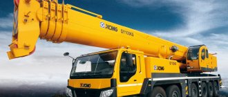
GOST 9692-71 “Self-propelled jib cranes for general purposes. Types and basic parameters." The standard applies to general purpose jib self-propelled cranes with a lifting capacity from 4 to 160 t, intended for construction, installation and loading and unloading operations.
GOST 1355-68 “Construction tower cranes. Standard sizes and main parameters." The standard applies to KB mobile tower cranes with a load moment from 25 to 1000 ton-m, intended for construction and installation work.
GOST 14274-S9 “Attached and self-climbing construction tower cranes. Basic parameters and dimensions." The standard applies to attached and self-climbing tower cranes with a load moment from 80 to 200 tf-m, intended for mechanization of the construction of buildings up to 150 m high.
GOST 7352—S5 “Electric gantry hook cranes. Types and basic parameters." The standard applies to electric hook gantry cranes with a lifting capacity from 1 to 50 t with one lifting mechanism, medium operating conditions, intended for servicing warehouses and loading and unloading areas.
GOST 10601-63 “Electric portal cranes with lifting capacity from 3.2 to 16 t. Types, main parameters and sizes." The standard applies to full-rotating electric gantry cranes for general purposes with a constant lifting capacity for all boom radii from 3.2 to 16 t inclusive, with horizontal movement of the load when the radius changes.
GOST 877-52. "Full-rotating railway cranes." The standard applies to railway full-rotating cranes with a lifting capacity of up to 150 t, designed to perform installation, reloading and other work on moving goods.
GOST 3472-63 “Electric hoists. Basic parameters and dimensions." The standard applies to electric rope mobile and stationary general purpose hoists with a lifting capacity from 0.25 to 5 tf with push-button control from the floor for medium operation.
GOST 13188-67 “Freight trolleys. Types, main parameters and sizes." The standard applies to cargo trolleys with a nominal load capacity from 50 to 3200 kgf, intended for intra-factory and intra-factory transportation of packaged cargo, as well as in warehouses and loading and unloading areas.
GOST 7485-55 “Single-rail trolleys with a grab. Basic parameters and dimensions." The standard applies to general-purpose electric trolleys with a lifting capacity of 2 and 3 t with a four-rope double-jaw grab for medium-duty operation, moving along suspended single-rail tracks.
GOST 7486-55 “Single-rail trolleys with a hook. Basic parameters and dimensions." The standard applies to general-purpose electric trolleys with a hook, with a load capacity from 1 to 10 tf inclusive, medium-duty operation, controlled from the cabin, moving on suspended monorail tracks, intended for transporting piece and packaged cargo.
For lifting machines for which there are no state standards, the load capacity, basic parameters and dimensions are established by the technical specifications for design (Article 15 of the Crane Rules).
The speed of movement of cranes controlled from the floor is assumed to be no more than 50 m/min, and that of their trolleys is 32 m/min (Article 17 of the Crane Rules).
Newly manufactured cranes intended for installation and other work that require precision and caution when landing loads must have appropriate low speeds for lifting and moving mechanisms (Article 18 of the Crane Rules).
The values of low speeds are given in state standards for this type of crane.
—
Parameters are technical data that characterize the design features of the crane. The main parameters include boom length, reach and lifting height of the load hook, lifting capacity, load moment, speed of lifting and lowering the load and rotation of the rotating part of the crane.
Arrow length is the distance (in meters) between the centers of the arrow heel axis and the axis of the head blocks. From boom length and angle
Its inclination to the horizon depends on the reach and height of the hook.
The reach of a cargo hook is the distance (in meters) from the axis of rotation of the crane to the vertical axis passing through the center of gravity of the lifted load (hook clip). Free hook reach is the distance (in meters) from the tipping edge to the vertical axis passing through the center of gravity of the load being lifted.
Hook lifting height is the greatest height to which the hook can be raised above the level of the platform on which the crane is installed, when the boom is in working position.
The lifting capacity of a crane is the maximum weight of a load that can be lifted by a crane without compromising the strength of its structure or losing stability. The amount of lifting capacity depends on the length of the boom and the reach of the load hook. For truck cranes, the lifting capacity with the smallest hook reach is several times greater than the lifting capacity with the largest hook reach.
In technical documentation, the dependence of the load capacity on the hook reach is usually depicted in the form of a graph - a curved line drawn in a coordinate system. On the vertical axis, the value of the lifting capacity is plotted on a scale, and on the horizontal axis, the value of the hook reach. The intersection points of lines drawn parallel to the axes form a curve showing the change in the crane's lifting capacity as the hook reach increases or decreases. The graph of the lifting capacity of the K-1014 crane with a boom length of 10 m shows that the crane can lift a maximum load weighing 10 tons with a hook reach of 4 m, and with a hook reach of 10 m the crane can lift a load weighing 1.6 tons. From the graph you can determine the weight of the load , which can be lifted by a crane at any possible hook extension.
Rice. 1. Lifting schedule and rights K-1014 (KS-3561)
The load moment is determined as the product of the calculated permissible load capacity of the crane (T) by the hook reach (m) at which the specified load is lifted. The load moment is measured in ton-meters (T~m). This parameter characterizes the technological capabilities of the crane, since it shows at what distance from the axis of rotation of the crane a load with a weight corresponding to the reach of the hook can be placed.
The speed of lifting and lowering a load is the distance the load moves (in meters) vertically per unit time. It is measured in meters per minute (m/min) or meters per second (m/s).
The speed of rotation of the rotary part is measured by the number of revolutions of the rotary part of the crane per unit of time (rpm).
Scope of application of tower crane
There are several industries where tower cranes are used. It's basically:
- Real estate construction;
- Shipyards;
- Large industrial workshops and warehouses;
- Special appointment.
In construction, cranes are divided by power:
Tower cranes are used in industrial and civil construction
- Low-power - used in low-rise construction. They can lift loads weighing up to 5 tons;
- Medium-power – they construct multi-storey general purpose facilities and industrial buildings. They have a gravity load of up to 25 tons;
- High-power equipment carries out installation of structural elements at industrial facilities and in hydraulic construction. In this case, the weight of the cargo can reach up to 100 tons.
In the hydraulic engineering field, cranes of all power levels can be used. The weak perform operations of an auxiliary nature, the medium strength - as pile spreaders for delivering concrete in containers during the construction of concrete monolithic elements. High-power equipment is used for installation of reinforced concrete structures.
When constructing low-pressure hydraulic structures with a mass of component elements reaching 80 tons, tower cranes with a large lifting capacity of over 100 tons are used. They are installed in pairs on the sides of the structure.
At ship repair and shipbuilding plants, two types of lifting equipment are used:
- With lateral limited supply (fixed taps);
- With lateral feed along the entire line of the slipway (mobile cranes).
Typical parameters of tower cranes
Fixed tower cranes are convenient due to the ability to rotate the tower 360 degrees, which increases the operating area. Mobile cranes on rollers have a simple design and are the most commonly used.
What to look for when choosing
The purchase or rental of a tower crane is made taking into account its main parameters and technical characteristics of the object. One of the key values is the load capacity of the unit, which determines its main purpose. Based on this criterion, the following mechanisms are distinguished:
- low power with a lifting capacity of up to 5 tons for servicing low-rise civil and private construction;
- medium power with a lifting capacity from 5 to 25 g for work on multi-storey civil and industrial construction sites;
- high power with a lifting capacity of 25-75 tons, in some cases up to 100 tons, intended for the installation of prefabricated elements of hydraulic structures and industrial construction sites.
Medium-power cranes are especially in demand as concrete spreaders for supplying concrete mixture in buckets to concreting blocks in the process of creating monolithic concrete structures.