June 14, 2019
First, let's define what a pump is (hydraulic pump, hydraulic machine).
A pump is a hydraulic machine that converts the mechanical energy of a drive motor into the energy of fluid flow.
In simple terms, we can say the following: the rotational energy, whether from the flywheel or from the tractor PTO, is transmitted through the hydraulic pump shaft, where the suction line has a larger diameter hole and the outlet has a smaller one.
In this regard, pumps are structurally divided into right-hand and left-hand rotation. Their rotation can be determined in two simple ways, the first visually (by eye), the second by the alphanumeric designation on the device body. There are several more “handicraft” ways to determine the direction of rotation of the pump - this is by using a pressure gauge, and by using a cuff for NSh (gear type) pumps; we will not dwell on them in this article; if you are interested, you can google it.
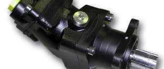
So, how to determine the rotation of an axial piston pump visually?
- We take the hydraulic pump and place it with its “hump” up.
- We look at the pump from the back cover. (Not the shaft, not the arrows on the case or the tag, since the tag or arrow on the case could have been changed or knocked down. On the cases of new models there are no such arrows at all; they are cast in the shape of a rectangular platform).
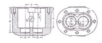
- I repeat that if this hydraulic machine is a pump, it has holes of different diameters (the hydraulic motor has the same diameter). So which side of the hole has a larger diameter determines the rotation (see the figure at the bottom of the article).
How to make hydraulics for a walk-behind tractor
Homemade hydraulics for a walk-behind tractor will help you perform braking by reducing oil flow. When the load distribution handles are set to the off position, the wheels can be completely locked.
To make hydraulics for a motor cultivator, you will need an oil pump with a high flow rate of the working fluid and medium pressure. This pump will act on the hydraulic motors.
They are installed on a steel walk-behind tractor frame, which must be made from a rectangular pipe. Hydraulic motors should be installed as close to the drive axle as possible so that they rotate the rear wheels.
To determine in which direction the rotation will occur, you will need a distributor. To do this, you can use used parts and components of the Belarus tractor.
Oil flow occurs through the spool. A special swing bushing for the front axle is mounted in the middle of the device. This design will avoid the need for a cardan shaft.
Thus, the front wheels will change the operating system. When turning the cultivator, the track width changes, and the front axle is responsible for this in the system. For this reason, it is made independently.
As axle shafts with turning pins, rotary stands are mounted in the cultivator on the right and left. Then you need to synchronize the installation of wheel rims and disks. Their relative position should be offset.
After installation and connection, it is necessary to check the operation of the entire structure. If any parts are not functioning well, then you need to check all connections for leaks. Then, after eliminating all the defects, they turn on again and check the functionality of the walk-behind tractor with the hydraulic control system. You should also adjust the operation of the steering and movement hydraulics.
Self-made hydraulics for a motor cultivator will reduce the effort required to cultivate a plot of land and optimize all agricultural processes.
Is it possible to use a hydraulic motor instead of a hydraulic pump and vice versa?
If we are talking about a hydraulic motor - this is a hydraulic machine that converts the energy of fluid flow into mechanical rotational energy, the direction of rotation is not important, since it is reversible, that is, it can be either right or left rotation.
Due to this feature, the hydraulic motor can be used as a hydraulic pump of any rotation. That is, if you replace the pump with a motor, nothing will change structurally, it will only be a little noisier and slower during operation.
Attention :
It is strictly not recommended to install a pump instead of a motor!
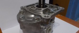
Installation rules for NSh gear pumps
| Home / Pumps / Oil gear pumps Ш and НМШ / Installation rules for NSh pumps |
Installation of the NSh pump
The pump must not be struck.
Before installing the pump, check whether the direction of rotation of the drive gear shaft, which is indicated on the pump cover, coincides with the direction of rotation of the drive (output shaft of the gearbox, electric motor, etc.)
The drive must prevent the transmission of radial and axial forces to the pump drive shaft, and also provide the possibility of its radial movements of up to 0.3 mm.
The pumps are fastened to the drive housing using bolts or studs with nuts, which must be securely tightened and protected from unscrewing.
The suction and pressure hydraulic lines are connected to the pump using flanges with O-rings.
The design of the connection of the suction hydraulic line must ensure its complete tightness.
The suction hydraulic line must ensure a fluid flow speed at the pump inlet of no more than 1.5 m/s and be as short as possible, with a minimum number of bends.
It is not permitted to install taps, filters or valves on the suction hydraulic line.
The pressure hydraulic line must ensure a fluid flow speed of no more than 5 m/s and also be as short as possible, with a minimum number of bends, narrowings and corner connections. If there are corner connections, the fluid speed should not exceed 3.5 m/s.
In the pressure hydraulic line of the pump, it is necessary to provide space for installing a control pressure gauge. Pressure loss in the system should not exceed 0.6 MPa.
Mechanical forces from deformations and movements of the hydraulic lines connected to it should not be transferred to the pump. In order to reduce the influence of vibration, pulsation, pressure and resonance phenomena on the pump, it is recommended to install a compensating link in sections of the pressure hydraulic line.
The rate of change in pressure in the hydraulic system to the nominal value should not exceed 350 MPa/s when the pressure increases and 1000 MPa/s when the pressure decreases. The filter device must have a nominal filtration fineness of no coarser than 25 microns and be located in a location convenient for maintenance.
To prevent contamination of the working fluid during refueling, it is recommended to equip the hydraulic system with a device for forced filling through a fine filter (25 microns).
The recommended volume of the hydraulic tank should be at least 1/3 ... 2-minute volumetric flow of the pump, depending on the operating mode of the machine (light or heavy), but twice the filled volume of the cavities of the hydraulic system and ensure the required temperature conditions.
A partition with a height of 2/3 of the oil level in the hydraulic tank must be provided inside the hydraulic tank between the suction and drain holes. The opening of the suction hydraulic line must be located at the bottom of the hydraulic tank at a distance of at least three pipe diameters from the wall of the hydraulic tank and at least two diameters from the bottom of the hydraulic tank. The drain hole of the hydraulic line must be located below the minimum permissible level of working fluid in the hydraulic tank.
The hydraulic tank must have a closed type oil level indicator. The air entering the tank through the breather must be thoroughly cleaned. The level of working fluid in the hydraulic tank should be 150 mm higher than the pump inlet. It is preferable to have a closed tank with an excess pressure of 0.02 MPa.
Hydraulic cylinders must have a device that prevents the formation of vacuum in the cavities of the cylinders and the hydraulic lines connected to them when lowering the working part of the machine. Otherwise, air may leak through the rod seals of the cylinders and the seals of the angular movable joints of the hydraulic line, which leads to intensive wear of pump parts and other components of the hydraulic system.
It is also recommended to use unloading devices in the cylinders that reduce the peak pressure when the piston approaches the extreme positions, which at the same time reduces the operating time of the hydraulic system in safety valve mode.
When installing and dismantling hydraulic drive elements, as well as when changing oil, cleanliness must be observed. The oil used serves not only as a working fluid for activating the machine's actuators, but also at the same time as a lubricant for the pump bearings. Therefore, contamination of the working fluid with mechanical impurities or the ingress of moisture into it causes the formation of nadir on the surface of the sliding bearings and disables the pump.
Applicability of gear pumps NSh-10
You should pay attention to which model NSh-10 is needed - with left or right shaft rotation. For example, the NSh-10U-3 pump with a rotor rotating to the left is used in hydraulic systems on motor graders D-122, DZ-98, and to the right - on A-120. The designation “L” in the marking indicates that the drive rotor of the device rotates counterclockwise. This letter is not present in the marking of a right-hand rotation hydraulic machine. The letter "U" indicates the design. Thus, the NSh-10U-3 gear pump is flat (U), right-handed, pressure version - group 3. The price of NSh-10U-3 is the same regardless of the version.
Left shaft rotation
Right shaft rotation
N Ш-10У-3 slot 416
Tractors: T-25 A/A-3/F, T-4A, T-4AP2, KhTZ-5020, VT-30, T-16M, TDT-55A, LHT-55, TB-1, MTZ-680/682 , MTZ-50/52, MTZ-80/82, MTZ-100/102, T-250, T-70S/V, T-90, T-90P, TT-4 all modifications, DT-75 all modifications. , dt-175MGG/S produced since 1989
Engines: MMZ, SMD14. 31A, A-01M, D-461, A-41, D-440, D-442, Ya MZ combine harvester modification.
Agricultural machines: DON-680, 1200, 1500; NIVA, Polesie-250, Sibiryak, Yenisei-1200, Kedr, KSKU-6, KS-6B, KSK-4, KSK-100, KPS-5G, KSG-F-70A.
Excavators: 302626, EO2626A, 302628, MG-50.
Tractors: YuMZ-6 of all mods, KhTZ-1410, KhTZ-3130, DT-175 of all mods (until 1989), T-25.01, T-35.01.
Excavators: E02621, E02629, E02621 in, 302627, EO-2101, EO-2621, 30-2301 (LTZ-60AV), PM-1.
Gear pump NSh 10U-3 (6 splines).
is engaged in the production and sale of spare parts for automobiles, crawler cranes and other special equipment. One of the company's activities is the sale of hydraulic equipment, such as a gear pump for special equipment. You can buy the NSh 10U-3 pump, find out about its availability or price in any convenient way: by filling out an application through the online store, sending it by e-mail or calling the manager (see the “contacts” tab).
The NSh 10 U-3 pump is produced in both left and right rotation. Left rotation means the drive rotor rotates counterclockwise. Right rotation - clockwise when viewed from the drive side.
The device is used to pump mineral oil into the hydraulic systems of various mechanisms, tractors, agricultural machines and other equipment, with a nominal pressure of up to 160 kgf/cm2. The pump is mounted on a power take-off shaft; it is possible to use the pumps in various stationary installations driven by an electric motor. Torque is transmitted using a splined connection between the pump shaft and the power take-off shaft, or another type of drive device.
The gear pump of the U, UK series is completely interchangeable with the MASTER NSh series pumps created on the basis of NSh32M, NSh50M and is their more economical analogue.
- NSh – gear pump;
- 10 – working volume;
- У – design;
- 3 – design for nominal pressure, 16 MPa.
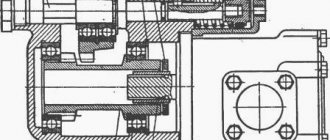
Overall and connection dimensions of the device:
Application on equipment:
| Left shaft rotation | Agricultural machines: SK-6-11, SK-6A, KSKU-6, KSKU-6A, KSK-4-1, KS-6, KS-6B, KSK-100, KSK-100A-1, KSK-100A , KS-6B-01, KS-6B-02, KS-6B-05. Tractors: T25A, T25A-3, T16M, T16MMCh, T16MG, T16MGMCH, TT-4M, TT-4M-01, T4-A, T4-AP2, TT-2, DT-75 all modifications, DT-175M/T /Since production since 1989. Engines: A-41 (until 1988), SMD-14BN (until 1989), SMD-14NG, SMD-18N, SMD-18N-03, SMD-19, SMD-20 , SMD-21, SMD-22, SMD-17KN, SMD-23, SMD-24, SMD-31A, SMD-22A (until 1984) |
| Right shaft rotation | Tractors: YuMZ-6 of all mods, KhTZ-1410, KhTZ-3130, DT-175 of all mods (until 1989), T-25.01, T-35.01. Excavators: EO2621, EO2629, EO2621V, EO2627, EO-2101, EO-2621, EO-2301 (LTZ-60AV), PM-1. Motor graders: A-120. Loaders: PEA-1, PEA-1A. Engines: D-65 |
Interchangeability of gear pumps NSh-10
| No. | MANUFACTURER | NSh-10 |
| 1 | JSC "Gidtoagregat", Pavlovo-on-Oka | B-3, E-3* |
| 2 | JSC "Hydrosila", Kirovograd | G-3*, U-3 |
| 3 | JSC "VZTA", Vinnitsa | B-3 |
| 4 | OPO "Omskagregat", Omsk | 3, E-3 |
| 5 | JSC "Gidravlik", Gryazi | G-3 |
| 6 | JSC "Agregat", Sim | D-3 |
| 7 | OJSC "Livgidromash", Livny | E-3 |
| 8 | JSC "Gidroprivod", Korenovsk | E-2 |
| 9 | PA "ZSOS", Smorgon | S-4 |
| 10 | RUE "ZhMZ", Zhitkovich | Zh-3 |
Note: B – 6 splines E – 4 splines * – four splines