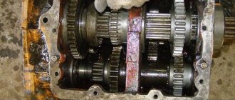
The movement mechanism with a separate drive has found widespread use on overhead girder cranes for general and special purposes with spans of more than 15 m. It consists of two or more independent drives installed on the working platforms of the bridge near the end beams and serves to drive one or more running wheels. The use of a separate movement mechanism eliminates the need for long transmission shafts and reduces installation and operating costs. With a separate drive, each end beam of the bridge is driven by its own drive, and the connection between the drives is carried out through the metal structure of the crane. Each drive consists of an electric motor, brake, gearbox and drive wheel.
Compact drives made in the form of a mounted vertical gearbox mounted on the splines of the drive wheel shaft and a flanged electric motor have found wide application in separate movement mechanisms. The brake is installed on a stand fixed to the gearbox or the coupling of the motor shaft with the gearbox.
The movement mechanisms of overhead crane trolleys are made according to the crane movement mechanism with a low-speed transmission shaft with a central or cantilever arrangement of a vertical gearbox on the trolley frame. The torque from the electric motor is transmitted through a gearbox to a transmission shaft connected to cylindrical drive wheels, or is transmitted directly to the drive wheel of the trolley, which is connected to another drive wheel by a transmission shaft.
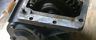
Rice. 3 - General view of the separate drive of the traveling mechanism of the overhead crane: a - with a vertical gearbox and a gear coupling; b - with a horizontal gearbox and a high-speed cardan shaft
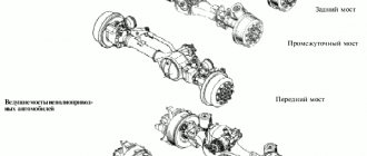
For overhead cranes and trolleys with a lifting capacity of up to 50 t, the chassis is made with four running wheels
In overhead cranes, the load lifting mechanism is located on the crane trolley. Depending on the purpose of the crane, the trolleys are equipped with one, two or, very rarely, three lifting mechanisms: the main one for the rated lifting capacity and auxiliary ones for the lifting capacity, which is 3-5 times less than the nominal for medium-lift cranes and 4-10 times for heavy-lift cranes .
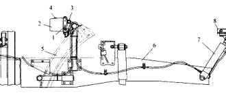
This mechanism consists of a cargo rope running from the drum and bending around the hook suspension blocks, bypass blocks and equalizing block, a gearbox equipped with a brake, an intermediate high-speed shaft and a drive electric motor. To gain traction in lifting mechanisms, a chain hoist is used, which is a system of movable (in a hook suspension) and fixed (bypass) blocks. Lifting mechanisms for cranes with a lifting capacity of 80...320 tons are carried out according to the same scheme, they differ only in the presence of an additional reduction gear or a second gearbox, with the help of which the output shaft of the main gearbox is connected to the drum. In this case, the second gearbox performs the function of high-speed transmission. The additional gear wheel is rigidly connected to the drum, and the gear is mounted on a separate shaft on supports and connected to the output shaft of the main gearbox using a gear coupling or mounted on the output shaft of the gearbox. To reduce the cantilever load acting on the gearbox shaft, an additional support-bracket is used, which is attached to the gearbox housing.
Rice. 4 — Kinematic diagram of the main hook lifting mechanism: 1 — engine; 2 - clutch, 3 - brake, 4 - gearbox, 5 - drum, 6 - pulley block, 7 - stationary pulley block
The lifting mechanisms of overhead cranes use normal and shortened hook hangers to connect the load hook to the lifting rope.
In a normal hook suspension (Fig. 5, a), the hook, through a nut on the shank, rests on a thrust bearing, which transmits the force from the hook to the traverse through a spherical washer. The traverse is hinged in the earrings and protective shields. An axis with blocks is fixedly installed in the upper part of the shields and earrings. The blocks can rotate in bearings. A sheet bracket is installed between the shields to prevent a rope block that is weakened when mooring a load from falling out of the stream. Depending on the diameter of the block, the gap between the bracket and the block is 0.15-0.3 of the rope diameter. If the multiplicity of the pulley is odd, an equalizing block is installed on the axis between the blocks. The nut is locked with a bar that fits into the slot of the hook. Washers and rings prevent lubricant from leaking out of the bearing cavity.
Rice. 5 — Hook pendants: a — normal; b - shortened
In metallurgy and construction, in the production workshop and warehouse, in transport and repair shops, when working with bulk and dangerous goods, overhead cranes are used to move large cargo, non-demountable units and much more. This equipment is designed for intensive work in a wide variety of, sometimes extreme, conditions.
Scope of application of lifting machines and mechanisms
The main task performed by lifting mechanisms is moving, lifting or lowering bulk, piece, pelletized materials. They are widely used in mechanical engineering, agriculture, and in production workshops on construction sites. It is customary to include devices intended for transporting people (escalators, lifts) into a separate category.
Depending on the scope of use, equipment has been developed that differs in the range of available functions and design. For example, at a service station you need to lift cars to a relatively small height. At the same time, the weight of the cargo will be impressive. Taking into account these operating features, jacks have been developed. Depending on the nature of the application and the characteristics of the structures being lifted, the power of the mechanisms may vary significantly. If there is a need to move along a free trajectory, self-propelled cranes equipped with a winch are used.
Taking into account the subtleties of use, enterprises install lifting equipment of various designs (there are more than 20 types of units of this type). To work with bulk materials, cyclic machines are installed. Movement along any trajectory is possible, which allows you to take into account the characteristics of a particular room. Auxiliary functions are performed by manipulators.
Purpose and design of an overhead crane
An overhead crane is used to move cargo around a workshop, warehouse, or other production facility. A crane bridge with a cargo trolley attached to it moves along the crane tracks laid along the walls, lifting and lowering the load.
According to the bridge design, cranes are divided into:
- Single beam. The bridge consists of one I-beam, at the ends of which end beams with running wheels are installed. In addition to the main cargo trolley, an additional console type can be installed. Cranes of this type are lightweight, but their lifting capacity, as a rule, does not exceed 10 tons.
- Double beam. Structurally, the bridge is composed of two rigid beams with end beams equipped with running wheels. In addition to the main one, the cargo trolley can be equipped with auxiliary lifting mechanisms. This type of crane has a large lifting capacity and is controlled from the cabin or remotely.
Main characteristics of the equipment
Choosing an installation requires taking into account the features of its future application, the type of materials and structures with which it will work. The key characteristics of lifting machines include the following parameters.
- Load capacity. It shows the maximum permissible weight with which the equipment can work without overload. When choosing, it is recommended to initially provide a 15% power reserve for the unit in order to ensure greater reliability and eliminate the likelihood of situations associated with increased wear of the mechanism drive.
- Travel speed, lifting height. Determined based on the characteristics of the technological process and the specifics of the operations performed.
- Boom reach, crane span. These parameters determine the distance through which the mechanisms can move, respectively, relative to the axis of rotation or between the rails.
- Available operating modes. The duration of switching on of the machines and their utilization rate depend on them.
Possible wind loads are also taken into account if the equipment is intended to be used outdoors. This parameter is important in order to eliminate the possibility of the unit tipping over.
Classification of lifting mechanisms by degree of rotation
The rotary crane freely rotates the load around a supporting axis. Such equipment includes tower and console cranes.
The part-turn crane provides rotation at an angle of up to 360 degrees. Often, these include cantilever stationary cranes, or cantilever cranes with a support on the wall.
A full-rotating crane can rotate a load 360 degrees or more from one extreme point to another along the axis of the support beam.
A fixed crane has no moving part, which ensures the rotation of the boom with a load relative to the central support. These cranes include overhead or gantry cranes located on guides.
Types of lifting machines
All types of lifting machines and mechanisms are classified according to several criteria:
- purpose (transportation, lifting, unloading/loading);
- degree of mobility (self-propelled, static, mobile);
- type of materials (bulk, pelletized, piece, liquid);
- level of automation;
- nature of movement (continuous, periodic).
In addition, units are produced that differ in operating principle: manual and electric devices, units with pneumatic drive.
Jacks
One of the main advantages of using a jack as a lifting device is the accuracy of positioning of the structures being lifted, regardless of their geometry, dimensions and weight. Mechanical, hydraulic, electrical, pneumatic models with a wide range of characteristics are available.
When choosing them, the load capacity is taken as the basis (for screw jacks its maximum is 1 t, for hydraulic jacks - 100 t) and lifting height (rod stroke). Specialized models are also available. Most often they are used at service stations for tipping cars on one side, stands used during repairs to secure other holding devices.
Winch lifting mechanisms
Load-lifting machines include winch mechanisms. They are used in construction, maintenance, and production to move structures in a horizontal or vertical direction. Models are available equipped with different types of drives:
- worm gear (they have a large gear ratio);
- chain, characterized by high efficiency;
- drum electrical devices with switching equipment with a rated voltage of 220 or 380 V;
- lever ones, which are distinguished by their minimal size and weight.
The main criteria for selection are traction force, rope capacity of the drum, speed of the cable, the ability to adjust operating parameters, weight of the product, load capacity.
Tali
We offer a large selection of hoist modifications with a wide range of characteristics. This allows you to select equipment taking into account the characteristics of future operation. Distinctive features of this type of units are high reliability, relatively high speed and height of movement, and load capacity. Hoists are often used as an auxiliary device in conjunction with crane equipment of any type.
To ensure high productivity, if the speed of operations is important, we are talking about structures with heavy weight, electric models are chosen. In case of possible interruptions in power supply, manual hoists predominate in areas with low work intensity. When purchasing, it is also worth considering the need to move the mechanism: there are stationary and mobile units.
Telphers
Hoists are an effective replacement for crane equipment during loading and unloading operations. The following types of such devices are produced: chain and rope. The lifting capacity of the units is up to 25 tons with a lifting height of up to 70 m. Control can be manual or remote (using a remote control).
Equipping with a carriage increases the functionality of the model due to the ability to move the hoist around the workshop or construction site. If it is necessary to ensure increased speed of movement of the rope or chain, the equipment is equipped with a frequency converter.
Blocks and pulleys
Blocks are widely used as an independent or auxiliary unit for lifting structures. They are available in single and multi-roller versions. Based on their purpose, the blocks are divided into outlet and cargo. The former are used to change the direction of movement of the cable, the latter - to move in a straight line.
Pull blocks are an integral part of lifting units, which is a system of blocks connected by ropes. There are speed and power devices (the choice depends on the tasks at hand). Within the framework of one lifting installation, several chain hoists can be used simultaneously. This solution is more efficient and allows you to reduce the load on each of them due to the even distribution of effort.
About metalworking
Processing of threaded surfaces is an operation that is carried out by removing a layer of material (chips) from the machined surface or without removing chips, i.e., plastic deformation. In the first case, we are talking about cutting a thread, and in the second, about rolling it. When assembling and repairing equipment and carrying out installation work, cutting or rolling threads is used manually or using hand-held mechanized tools.
A threaded rod that has a screw surface along its entire length or some part of it is called a screw , and a hole that has a screw surface is called a nut .
Thread elements (Fig. 1) are certain numerical parameters that characterize the thread.
Thread pitch P is the distance in millimeters between the tops of two adjacent threads, measured parallel to its axis.
Profile height H is the distance from the top of the thread to the base of the profile, measured in the direction perpendicular to the thread axis.
Rice. 1. Elements of triangular thread: α - profile angle; P - thread pitch; d is the outer diameter of the thread; d1 - internal thread diameter; d2 - average thread diameter; H - thread profile height
Rice. 3.24. Elements of triangular thread: a - profile angle; P - thread pitch; d is the outer diameter of the thread; d1 - internal thread diameter; d2 - average thread diameter; H - thread profile height
Profile angle α is the angle between the straight sections of the sides of the thread profile.
The outer diameter of the thread d is the largest diameter of the thread, which is measured along its tops in a direction perpendicular to the axis.
The internal diameter of a thread is the smallest distance between opposing thread roots, measured perpendicular to the axis.
The average thread diameter d2 is the diameter of a conditional circle drawn in the middle of the thread profile between the bottom of the recess and the top of the protrusion, measured in the direction perpendicular to the axis.
Tools and devices for cutting external and internal threads by hand. To cut external and internal threads manually, special thread-cutting tools (taps and dies) and devices are used to create the torque on the tool necessary to provide cutting forces during the processing process.
The tap (Fig. 2) consists of two parts: the working part, which ensures the cutting process, and the tail, at the end of which there is a square protrusion for installing the driver. The working part of the tap includes a cutting (taking) part, which ensures the removal of the main allowance for processing, and a calibrating part, which carries out the final processing of the thread. Taps for manual threading are made in the form of sets of two or three pieces (rough, medium and finishing), which are marked with circular marks on the tail part (one, two and three marks, respectively).
Rice. 2. Tap: 1 - thread (turn); 2 - square; 3— shank; 4 - groove
To create torque on the cutting tool (tap), special devices are used - wrenches of various designs.
The universal driver (Fig. 3) is a frame with two crackers - movable and fixed, forming a square hole and securing the tail part of the tap.
Rice. 3. Sliding knob: 1 - frame; 2 - coupling; 3 - handle; 4, 5 - movable and fixed cracker, respectively; a is the side of the square
A driver with switching cams (safety) (Fig. 4, a) allows you to protect the tap from breakage by disengaging the cams of the body and bushing when the force transmitted by the driver exceeds the permissible value.
The end driver (Fig. 4, b) is used when cutting threads in hard-to-reach places, as it allows you to work with one hand.
A ratchet driver (Fig. 4, c) is used for cutting threads in hard-to-reach places, when the driver can be turned at a small angle at a time.
Rice. 4. Gates: a - safety: 1 - body; 2 - bushing; 3 - spring; b - end; c - with ratchet
A die is a tool for cutting external threads, consisting of two parts: a tapping and a calibrating one. Their purpose is the same as that of the corresponding parts of the working part of the tap. When manually cutting threads, dies of various designs are used.
Round dies (Fig. 5, a) are a threaded ring with several grooves for forming cutting edges and removing chips. They are made whole and cut. Due to their springy properties, the dies allow you to adjust the average diameter of the thread being cut.
Square dies (Fig. 5, b) consist of two halves, which are secured in a special frame with handles - a clamp.
The clamp provides the ability to regulate the average diameter of the thread being cut.
Rice. 5. Threading dies: a - round: 1 - intake part; 2 - calibrating part; 3 - chip groove; b - square (sliding): 1 - die; 2 - die
To create a torque and ensure the cutting process when cutting external threads with dies, special devices are used - cranks (for round dies) and clamps (for split dies).
The driver for round dies (Fig. 6) is a round frame with a recess in which a round die is placed, held from turning by three locking screws. The fourth screw allows you to adjust the average diameter of the thread when using a split round die to cut it.
Rice. 6. Driver for round dies.
The die (see Fig. 5, b) is a square frame with protrusions into which the grooves of the die fit. One of the halves of the die can be moved using a screw, adjusting the average diameter of the thread being cut.
Hand-held power tools for cutting internal threads can be equipped with either a pneumatic or an electric drive.
A pneumatically driven thread cutter (Fig. 7) is designed for cutting small diameter threads. The pneumatic motor 1 rotates the spindle 4. When you press the handle 3 of the housing, threading occurs. When the pressure on handle 3 is released, the spindle 4 moves under the influence of the spring and its movement is reversed. In this case, the tap 5 is rapidly unscrewed from the hole in the workpiece 6. The tool is turned on by pressing the trigger 2.
Rice. 7. Thread cutter with pneumatic drive: 1 - pneumatic motor; 2 - trigger; 3 - handle; 4 - spindle; 5 - tap; 6 - blank
Electrically driven thread cutter (Fig. equipped with a built-in electric motor, reversing mechanism and gearbox.
Rice. 8. Electrically driven thread cutter
Preparing rods and holes for threading. During the thread cutting process, not only the removal of a layer of material from the surface of the workpiece occurs, but also plastic deformation of the machined surface, which is accompanied by the extrusion of part of the workpiece metal from the recesses of the thread turns to the tops. This phenomenon must be taken into account when determining the diameters of rods and holes for threading. Therefore, it is advisable to determine the dimensions of the workpieces using reference tables, in which they are given taking into account all the factors affecting the cutting process.
In practice, the diameter of the hole for the thread is chosen equal to its nominal size, reduced by the pitch. For example, when cutting an M10 thread, the hole diameter should be 10 - 1.5 = 8.5 mm.
When cutting external threads, the diameter of the rod should be 0.1 ... 0.2 mm less than the nominal diameter of the thread, depending on its size.
When processing external and internal threads, it is necessary to adhere to a number of rules.
- Manual threading must be done with the tap or die generously lubricated with machine oil.
- When cutting threads by hand, you should periodically cut off the resulting chips by moving the tap or die back 1/2 turn.
- After cutting the thread, it is necessary to control its quality: by external inspection (avoiding scuffing and torn threads) and with a thread gauge, the bore of which should be screwed on easily, by hand.
The rules for cutting external threads manually are as follows.
- Before cutting the thread, check the diameter of the rod, which should be 0.1 ... 0.2 mm less than the nominal thread size.
- Make a chamfer at the top of the rod so that it is concentric with the axis of the rod. In this case, its diameter should not be less than the internal diameter of the thread, and the angle of inclination relative to the axis of the rod should be 60°.
- The rod should be firmly secured in the vice, checking its perpendicularity to the clamping jaws using a square.
The rules for processing internal threads manually are as follows.
- Check that the diameter of the hole matches the size of the thread being cut.
- Check that the hole depth meets the drawing requirements when cutting blind threads.
- Using a square, check that the tap axis is perpendicular to the plane of the workpiece in the hole of which the thread is being cut.
- Use all taps in the set when cutting threads.
- Periodically clean blind holes from chips when cutting threads into them.
Threading on pipes is carried out using special tools - clamps and thread-cutting dies.
A die with sliding dies (Fig. 9) is a device most often used for cutting external threads on pipes. The die is equipped with a set of sliding dies for cutting threads with a diameter of 1/2…3/4; 1…11/4; and 11/2…2″. The clamp is mounted in such a way that four dies 5 moving in its body 1 can simultaneously approach the center or diverge from it. The movement of the dies is ensured by a special rotary device driven by a handle 4. The precise installation of the dies to the size of the thread being cut is carried out using a dial located on the body, and the installation movements are carried out by a worm gear 3. After installation, the position of the dies is fixed with a special device - a “pawl”. The cutting force is transmitted to the tool using handles 2.
Rice. 9. Jig for cutting pipe threads: 1 - body; 2 — handles; 3 - worm gear; 4 — handle for moving dies; 5 - dies
A round thread-cutting comb (Fig. 10, a) is used for cutting pipe threads on lathes and drilling machines. Combs are produced in sets of four. Thread cutting is carried out using a special self-opening screw-cutting head (Fig. 10, b).
Rice. 10. Round thread-cutting comb (a) and self-opening head for attaching it (b)
To facilitate the operation of the tool and improve the quality of threads obtained when cutting threads, COTS is used. Their choice depends on the material of the workpiece being processed. For example, an emulsion is used to cool steel workpieces (structural, tool and alloy steel). Kerosene should be used to cool cast iron and aluminum. Threading in copper, brass and bronze workpieces can be done without cooling.
Rules for working with lifting machines and mechanisms
Units that have a registered permit for operation are allowed to work on lifting loads. The document is drawn up on the basis of a set of tests performed. The operator must have appropriate technical training and undergo training. Particular attention is paid to proper fixation of the suspended structure and lifting hinged mechanism.
In the absence of permanent fastening, position control during movement is carried out directly by the slinger, operator, or loader. For the coordinated work of each of the specialists in the conditions of an ongoing construction or production site, pre-agreed signal gestures are often used.
In some cases, there is a need for additional protection of suspended goods from possible damage and mechanical influences (such situations occur especially often when working with substances that pose an increased chemical, explosion, and fire hazard). When automating equipment, the movement algorithm depends on the parameters and properties of the material, and the features of the technological process.
Safety precautions
Standard safety requirements for working with lifting mechanisms, regardless of their design features and scope of use, are admission of persons over 18 years of age wearing special clothing and personal protective equipment after completing training, instructions, and passing exams to determine the skills necessary to perform the assigned tasks. You also need to do the following:
- check the serviceability of the unit components and gripping devices;
- make sure that the lighting level is sufficient for work;
- use for tying slings that correspond in their parameters to the weight of the structures being moved;
- transport small goods in a container;
- do not leave structures hanging during breaks;
- do not allow lifting of structures that are frozen to the ground, concreted, or covered with earth;
- maintain at least 0.5 m when lifting to the highest point of stationary structures along the trajectory of movement;
- do not allow movement over people.
After completing the planned work, the hook is raised and the switch is turned off. Load grippers are removed to a place intended for storage. If any malfunctions are identified, they are reported to the shift worker or workshop foreman.
Lifting devices from professionals
Order the manufacture of a crane from our company. Crane has been designing, manufacturing, installing and servicing lifting devices for various applications for more than 10 years. We produce overhead, cantilever, gantry cranes, trestles, and mobile devices. On an individual order, our specialists will develop a crane with individual characteristics for your business, we carry out orders for non-standard designs.
Contact us in any convenient way
, request a call back or visit our office in Moscow, we will answer any questions you may have. Our managers will always help you choose the right crane modification.