UAZ generator 6651 3701 connection diagram
UAZ vehicles can have different generators; this article describes generators produced by KZATE 6631.3701 and 6651.3701
Generators 6631.3701 with double pulley for ZMZ engines
Generators 6651.3701 with a single pulley for UMZ engines
Apart from the pulley, the generators are no different and are completely interchangeable when replacing pulleys. You can install another generator without replacing the pulleys.
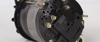
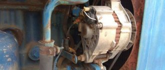
The generator consists of a housing, stator winding, rotor, diode bridge and built-in voltage regulator.
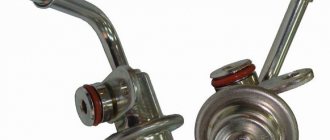
The peculiarity of this type of generator is that a cap is made at the rear of the generator, in which a voltage regulator is mounted. This design improves the splash protection required for SUVs. When repairing such generators, it is not immediately clear how to arrange the wires connecting the voltage regulator and the generator.
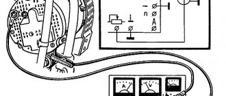
Generator circuit 6631 and 6651
When starting, the initial excitation comes from the battery. Then, when the generator starts working, it itself transfers part of its current to excitation.
When the ignition is turned on, a positive signal comes to terminal B, which goes to point B of the regulator via the blue wire, and the voltage regulator transistor opens. The excitation current begins to flow through the circuit - from point 15\1, through the light bulb, to point D, then along the green wire to the generator brush assembly, through the brushes into the excitation winding, then through the open transistor of the regulator to ground. To power the regulator, the plus must be at its point B. This plus goes from the brush assembly via the orange wire to the additional rectifier, and from there via the red wire to point B of the regulator. The additional rectifier itself does not work yet. The current flowing in this circuit lights up a light bulb, which confirms that the excitation circuit is intact and the generator is ready for operation. A small current of this circuit magnetizes the rotor, when the rotor begins to rotate, its magnetic poles, replacing each other, create a changing magnetic field and an EMF appears in the generator winding, that is, the generator is excited and begins to work.
The light bulb, with its resistance, limits the initial excitation current to 100 mA. This current is sufficient to excite the generator. The light is on, indicating that the excitation circuit is intact, the excitation current is flowing and the generator is ready for operation.
Next, the starter spins the engine, and the rotation of the magnetized rotor excites an EMF in the generator, that is, it begins to work. Now the generator supplies current to the load, charges the battery and creates an excitation current for itself.
This generator uses a circuit with additional diodes to power the excitation winding. An additional rectifier consisting of three small diodes is provided in the diode bridge of the generator.
When the engine starts, the generator is excited from the battery, through the ignition switch and through the light bulb. When the generator is excited, the excitation current flows through an additional rectifier already inside the generator, without using external circuits and the ignition switch. This scheme turns out to be more reliable and eliminates accidental battery discharge.
Types of diode bridges
Modern generators can be equipped with bridges that operate on several diodes. You need to understand the differences between them. After all, important characteristics of the car depend on this.
Six-diode
This type of bridge is more popular and more often used. The high level of popularity of such a diode bridge is easy to explain.
It can be used for both delta and star windings. Therefore, many leading manufacturing companies give it preference.
Eight-diode
If the stator winding was made with a star, then only such a diode bridge can be used. The advantage is that such bridges are much more powerful.
What could happen to the generator?
If, when you turn on the ignition, the battery discharge light on the instrument panel does not light up, then the generator will not work after starting the engine; look at the voltmeter; the arrow will remain to the left.
If the engine starts and the light does not go out, then the generator is not working (check the belt)
The generator works, but the battery discharges quickly when parked. Instead of a 112 V regulator, a 112 A regulator is installed
If the light comes on while driving, it means the generator has stopped working.
If the paw blinks, it means it's time to replace the brushes.
If the light is dimly illuminated, the generator is faulty
If the light bulbs glow too brightly, flicker, and the battery becomes wet, then the voltage is too high and you need to urgently replace the voltage regulator.
If the light goes out only at high speeds, then the generator is faulty
If the generator makes loud noise, the bearings need to be replaced. If the generator is very old, then it is better to replace the entire generator.
In case of any malfunction, you need to go to where the generator will be repaired, otherwise in two hours you can be hopelessly stuck
If the generator 6631.3701 is broken, and there is a replacement generator without additional diodes 6631.3701-01, then you can install it, but the light bulb will not work. Read the details at the end of another article
Another connection between the generator 6631.3701 (6651.3701) and the voltage regulator YA112V will also work, since the circuit remains the same.
Source
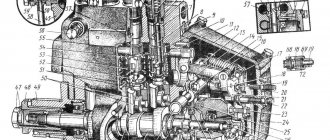
Electrical circuit maintenance
Maintenance of the tractor circuit can be done with your own hands or with the help of an electrician. The main thing is that this happens regularly and that all terminals and fastenings are checked. If necessary, it is necessary to clean the necessary parts from dirt and dust.
The starter requires cleaning every 3000 hours of use. To do this you need to do the following:
- dismantle the starter;
- remove dirt;
- remove the casing that performs protective functions;
- check the brush-commutator assembly.
Then the starter must be reassembled and the insulation on the wires, the connections on the plugs, and the integrity of the wires checked.
UAZ generator 6651 3701 connection diagram
Generators type 6631 and 6651 produced by KZATE are designed for UAZ vehicles.
On cars with ZMZ engines, a two-belt generator drive is used, so 6631 generators are equipped with a double pulley
6631
6631-01
On vehicles with UMZ engines, a single-belt generator drive is used, so 6651 generators are equipped with a single pulley
6651 6651 -01
Cars of older production were equipped with an old instrument panel, which did not have a battery discharge warning light.
In this case, generators 6631.3701-01 (DV ZMZ) and 6651.3701 -01 were used, made according to a simplified circuit without additional diodes
When replacing these generators, you need to install a voltage regulator (tablet) Y112A
Cars of newer releases were equipped with new instrument panels in which a battery discharge monitoring lamp was installed.
Maintenance of devices at MTZ
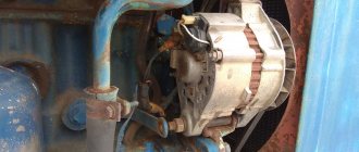
During operation, oil particles and dust accumulate on the generator, which should be removed with a clean rag. If dirt has accumulated in the internal cavities of the equipment, the unit must be removed for disassembly and cleaning with a rag moistened with gasoline. The formation of a layer of oxides on the terminals or destruction of the insulation of the wires of the tractor on-board network is not allowed.
When starting the engine, the control lamp should go out (on some tractors the indicator is allowed to blink in idle mode; when the frequency increases to 1400 rpm, the lamp turns off).
Do not operate equipment with a damaged pulley or fan impeller. It is recommended to periodically check and adjust the belt tension (deflection arrow 30 mm with a load of 3 kg). An over-tensioned drive will overload the rotor bearings. Due to wear of the elements, the normal clearance between the rotating unit and the stator is disrupted. Cracks or tears in the belt cause the drive to slip.
UAZ generator 6651 3701 connection diagram
These generators are in the same housing, but have circuit differences depending on the type of engine for which they are intended
| 14 Volt, 55 Ampere | |||
| 6631.3701 | UAZ with engine ZMZ 4021.70 | Double pulley | DD, New instrument panel |
| 6631.3701-01 | UAZ with engine ZMZ 4021.10, 410.10 | Double pulley | without DD, Old instrument panel |
| 6651.3701 | UAZ with engine UMP 4178.10, 4218 | Single pulley | DD, New instrument panel |
| 6651.3701-01 | UAZ, with engine UMZ 4178.10 | Single pulley | without DD, Old instrument panel |
| 5101.3701- 01 | GAZ 3309 D245.7 E2 28 Volt 35 A | Diesel engine |
Frequent problems and their diagnosis
If after starting the engine the control indicator does not go out, then it is necessary to check the condition and tension of the belt. Then you should inspect the connection points between the wiring and the terminals for the presence of oxidation of the elements. If performance is not restored, you need to check the windings using a test lamp. Additional testing is carried out using a voltmeter at the nominal operating mode of the diesel engine. The voltage at the outputs should not fall below 12.5 V when switching an external load (for example, headlights and parking lights).
Uniform extraneous noise during equipment operation occurs due to loosening of the pulley nut or wear of the ball bearings. To check, you need to remove the belt, check the tightness of the pulley by hand and rotate the rotor. Metallic knocks or jerking indicate wear on the bearings and contact between the rotor and stator plates. With further use, irreversible damage to parts will occur.
The nut is tightened with a wrench. If the mounting hole in the pulley is broken, then a new part must be installed. The bearings are tightened using a screw puller, and the generator parts are simultaneously diagnosed.
The article describes the main defects of generators on MTZ-82; we ask readers to leave their feedback describing the breakdowns and troubleshooting methods.
How is the replacement performed?
Let's say checking the diode bridge shows that there is a problem. It is necessary to disconnect all wires from the generator, remove and disassemble the device. In some models, the part is attached directly to the unit with bolts, but there are devices in which the housing must be removed to access the rectifier.
Next, as part of the repair, faulty diodes are replaced - if this is economically feasible and it is difficult to find the required generator model on sale. Or they change the component entirely. Upon completion of work on the stand, the serviceability of the component and the electrical system as a whole is checked using a multimeter, and the part is assembled and installed on the car.
You can check the diode bridge yourself if you have the time and skills to disassemble the generator. But even after checking and detecting faulty diodes, you will need to select and correctly install a new element instead of the faulty one. Remember that a faulty generator can cause failure of expensive electrical equipment, short circuits and spontaneous combustion of the car. Therefore, it is better to trust repairs and diagnostics to car service technicians, who will definitely be able to call you correctly!