Turn on the engine and test the parking brake by waiting for the parking brake signal to go out.
Then follow these steps:
- Test the seat adjustment and safety belt position.
- Select a drive. Full cannot be used on highways or hard ground - this increases fuel consumption and wears out tires faster.
- Select the desired motion control mode.
Attention! When turning the forklift, make sure there is enough clearance to clear the rear of the vehicle. - Engage the gear using the shift lever.
Attention! Do not change from a high gear to a low gear with a sudden jerk while moving. It is very dangerous. To set a low gear, first wait until the engine reduces speed. - Start moving.
Do not drive in reverse at high speeds or at full throttle.
Checking equipment before starting work
Regardless of his experience and experience with other types of forklifts, the operator must carefully study the operating instructions for the new model. After this, you should familiarize yourself with the control panel interface, the location of all levers and other controls. It is important to determine whether the functionality and capabilities of the excavator are suitable for the task at hand.
The driver can operate the excavator in two positions:
- facing forward . The controls are accessible as in any other tractor: steering wheel, clutch, brakes, gear lever, etc.;
- facing backwards . Controls for bucket, boom, stabilizers, etc. are available for use.
You should also pay attention to the additional functionality of the model. This includes the ventilation, air conditioning, all-wheel drive control, boom length and other capabilities. After this, you can begin to check the operator’s safety: safety belts, rollover protection functionality. This also includes auditing the integrity of hydraulic hoses, compliance of tire pressure with standards, the presence of a fire extinguisher and other protective equipment.
Test operation
Once in the operator's seat, fasten your seat belts. After this, you can start the engine and let it warm up. The pillar, bucket and stabilizers should be off the ground at this time.
While sitting facing forward, you need to select the main bucket control lever. It's easy to use. If you push it towards yourself, the bucket will rise. To lower, you need to move the lever - the bucket will move down. Moving the control lever to the right will cause the bucket to scoop up soil, and in the opposite direction will cause soil or rock to be pushed away.
Checking the solenoid valves 35/903500 crab stroke.
To test the solenoid valves, we need a multimeter to measure resistance.
We measure the resistance of the valve winding with a multimeter and check whether we have a short circuit or break in the electronic coil on the control valve.
It is also recommended to visually inspect the condition of the valve, whether its body is broken, whether the connector on the valve is intact.
Checking the solenoid valve JCB 35/903500
Test digging
Before starting to move, you must release the handbrake and engage first gear. After the tractor is adjusted to the work site, you need to check the ground clearance. Using the throttle valve, the optimal engine speed is fixed: 850. The next step is to set the stabilizers. After completing the above steps, you can open the bucket.
When digging, the JCB backhoe loader is controlled in the following sequence. The main working body is brought to the place where the hole is to be dug. Using the left lever, the bucket is lowered to the ground, and the right one allows you to scoop up soil with the bucket. In the closed position it rises up. Next, the bucket moves to the dump site and opens using the right lever. To continue operation, the boom rotates to its initial position.
Checking the integrity of JCB 3 CX harnesses and wiring.
You need to check the wiring from the sensors to the crab drive control unit, and also measure the power on the unit itself. Often there is damage to the harness on the frame, breaks and short circuits to the housing of the power or signal terminals, both sensors and valve actuators.
Example 1. Damage to the insulating layer due to mechanical damage.
JCB 3CX harness insulation failure (example 1)
Example 2 . Short circuit of the power wire to the ground (body) of the JCB 3CX , as a result of which the insulation melted and the wire stuck together in a common bundle. Here we had to completely open the entire harness and restore the electrical wiring, because the neighboring wires were also melted and damaged.
Shorting the power wire to the JCB 3CX body (example 2)
The melted wire goes far into the bundle and in order to get to it, the bundle has to be opened and repaired.
JCB 3CX harness insulation failure (example 3)
Backhoe Loader Controls
In models with a simplified control system, one lever is used to manipulate the shovel (indicated by the letter A in the figure). There is a button B on the handle, which instantly disconnects the transmission from the power plant after pressing. Thanks to this, all the engine power will be redirected to the operation of the loader.
Raising and lowering the boom; rollback forward or backward is initiated by one lever according to the standard “+” control scheme for these cases. You can choose a combination of specific manipulations. To do this, the lever moves between four main directions. For example, in order to lift a shovel, the lever must be moved back. At the same time, if you move it to the left, the shovel rolls back.
That is, in cases where the control lever moves to the left and back, the shovel rises and rolls away. The speed of manipulation directly depends on the amplitude of movement of the lever: the more, the faster. The lever itself is equipped with a spring that allows it to return to its original position. The loader will remain locked in the selected position until the control lever is commanded to perform any operation.
Next to the control there is a label that provides complete information about the relationship between the movements of the lever and the response of the working bodies. We'll talk about them below.
JCB 3CX Super: characteristics
Some more interesting technical data:
- The weight of the device is 7725 kg.
- Engine power – 92 liters. With. (or 68.6 kW).
- Digging depth – 4.37 m.
- The breakout force of the bucket is 6227 kgf.
- Bucket volume – 1 m3.
- The maximum breakout force of the bucket is 3217 kgf, with a hinged bottom - 6324.
- Pump flow – 154 l/min.
- The approach angle is 74°.
- Departure angle – 19°.
- The angle at the top of the obstacle between the wheels is 118°.
- Unloading height – 2.64 m.
- Thickness of the cut layer – 0.23 m
Return to digging position
The function is necessary in order to quickly switch to digging mode from the forward rolling position. If this mode is selected, the switch will cut off the oil pressure automatically at the moment when the shovel reaches the position required for digging.
In order to use the functionality, the “return to digging activation” switch (indicated in diagram A) should be moved to the “on” position. After the switch indication turns on, pull the control lever all the way to the left. The operator will feel a slight resistance when going through the roll back position. The lever must be released. It will remain in this position until the bucket reaches the desired position. And only after that it will automatically move to a neutral position.
If you no longer need to use a function, simply turn off the corresponding switch. Its indication will go out.
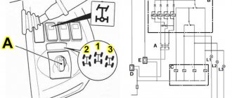
Steering (steering) on all four wheels JCB 4WS, trail to trail mode.
Track-to-track mode turns all four wheels in the opposite direction, providing better maneuverability in tight spaces. To switch to track-to-track control mode, turn the three-position switch “A” to the left position (2).
Trail to trail control mode JCB 3CX
Electric valves (35/903500 ) involved in the 4WS , next to next.
Valves involved 4WS JCB 3cx
Turn left (track to track) 4WS . When the steering wheel is turned to the left, the inner spool A rotates a few degrees relative to the outer spool B and sends a pressure signal to the relief valve 43B and through the LS to the priority valve.
4WS turn left (track to track) JCB 3CX
The rotor blades apply pressure to one side of the rear hydraulic cylinder 41 , turning the rear wheels to the right, at the same time, oil under pressure on the other side of the rear hydraulic cylinder 41 is supplied to the front hydraulic cylinder 40 , therefore, the front wheels turn to the left.
Turn right (next to next) 4WS.
Turn right (track to trail) JCB hydraulics
Let's take a closer look at the JCB hydraulic diagram in 4WS mode.
4WS trail-to-trail adjustment hydraulic diagram JCB 3cx
Electrical circuit for controlling the rotation of JCB wheels in 4 WS “track to trail” mode.
4 WS four-wheel steering mode, the CRAB 4 WS SOL X (12) and 4 WS SOL Z (11) valves are activated , while the 4 WS mode activation indicator on the front and side panels will light up.
Electrical diagram, 4WS mode enabled (2nd mode to the left) JCB diagram
When the 4WS the corresponding indicators 13 on the front and right side panels light up.
4WS JCB mode indication
Easy Controls System
On models equipped with Easy Controls, the loader attachment is controlled by a single lever (A). Its handle has a quick transmission reset button (B). Thanks to this, you can quickly free the power plant from additional load and direct all the power to do the job.
Individual movements – lowering, lifting, rolling away – are activated according to the standard “+” scheme. The combination of different movements is achieved by moving the control lever and holding it in the appropriate direction. For example, to roll forward and lower the shovel, you need to move the control to the right and forward. And vice versa, if you move the lever diagonally to the left and back, the shovel will roll back while lifting.
Easy Controls system extended
An extended Easy Controls system is installed on a number of machines. They use the right lever to control the operation if the operating mode was selected using a rocker switch. If the seat is facing forward, control lever A can be activated using button C. To do this, press and release it. And to turn it off, just put the toggle switch in the central position. Pressing button C again will quickly disengage the transmission.
When the seat is facing rearward, toggle switch E should be moved to the loading position. To control the operation of the loader, press and hold switch C located on the right lever. At this time, a warning signal will sound. When the switch is released, the loader control is disabled and the warning signal stops.
The control lever can be used to give both separate commands according to the “+” scheme, and combined ones in the same order as described above.
Reasons why the crab passage does not work, what needs to be checked?:
- Integrity of fuses.
- Three position crab switch 701/42700
- Non-contact wheel position sensors on the front and rear hydraulic cylinders 701/80312
- Electrical wiring malfunction, short circuit, break, oxidation.
- Gap between sensor and disk on hydraulic cylinder (adjustable)
- Solenoid valves JCB 02 124661
- Electronic crab control unit 704/21600
So, let's start checking. First, check the fuses. They are located on the right side, behind the gear shift knob.
JCB 3CX fuses