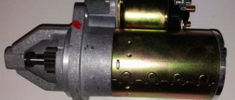
On modern MTZ tractors, the engine starter consists of an electric motor, a starter retractor relay and a drive mechanism. The design is reliable and thoughtful, so it usually lasts for many years without any problems. But if the load is exceeded while the tractor is operating, the traction relay may burn out in the area of the bolt fastenings. How does the MTZ starter solenoid relay work? What is the difference between traction relays on tractors 80, 82, 1221 and others? How to replace a burnt out starter relay? We will answer these and other questions later in the article.
Fuses and relays for the Belarus MTZ-82.1 tractor
Electrical fuses are designed to protect against overloads and short circuits in electrical circuits.
Molded Panel Instrument Fuses
Three fuse blocks for electrical circuits are mounted in the instrument panel with a molded panel. To access the fuses located in the instrument panel of the Belarus MTZ-82.1, 80.1, 82.2 tractor, you need to unscrew screw 2 and fold back panel 3.
Fig.29. Access to fuses located in the instrument panel with molded panel
1 – instrument panel; 2 – screw; 3 – panel.
Fig.30. Fuses located in the instrument panel with molded panel
Purpose of instrument panel fuses with molded panel
1 - 15A - Brake lights, terminal (6) and terminal (8) trailer socket. 2 - 15A - Road train sign lights (if equipped), rear work lights, cabin lighting. 3 - 15A - Hazard warning lights. 4 - 25A - Front and rear windshield wipers, front window washer. 5 - 15A - Sound signal. 6 - 25A - Main beam of road headlights, signal lamp for turning on the main beam of headlights. 7 - 25A - Front working lights, signal beacon (when installed). 8 - 25A - Power supply for the heater fan control circuit or power supply for the heater fan 80-8101720. 9 - 25A - Power supply for consumers operating when the starter switch and devices are in the "devices on" position: devices, speed sensors, power supply to fuse 15 and 16. 10 - 25A - Power supply for the electric motor of the fan-heater (when installing the fan-heater 80- 8101720 this fuse is not used); 11 - 7.5A - Left side parking lights, trailer socket terminal (7), license plate lighting. 12 - 15A - Side lights on the starboard side, terminal (5) of the trailer socket, instrument lighting. 13 - 7.5A - Low beam of the left road headlight. 14 - 7.5A - Low beam of the right road headlight. 15 - 7.5A - Power supply for instruments, speed sensors, warning lamp units, emergency sound alarm (buzzer) and parking brake relay breaker. 16 - 15A - Turn signal relay, glow plug block, glow plug relay coils.
Molded Panel Instrument Fuses
Three fuse blocks for electrical circuits are mounted in the instrument panel with a molded panel (installed upon request to replace the panel with a molded panel). To access the fuses, unscrew two screws 2 and open the cover of the instrument panel 1.
Fig.31. Location of fuse boxes in a molded panel instrument panel
1 – instrument panel cover; 2 – screw.
Fig.32. Placement of fuses in the instrument panel Belarus MTZ-82-1, 80-1, 82-2 with a molded panel
Assignment of molded panel instrument fuses
1 - 15A - Brake lights, terminal (6) and terminal (8) trailer socket. 2 - 15A - Road train sign lights (if equipped), rear work lights, cabin lighting. 3 - 15A - Hazard warning lights. 4 - 25A - Front and rear windshield wipers, front window washer. 5 - 15A - Sound signal. 6 - 25A - Main beam of road headlights, signal lamp for turning on the main beam of headlights. 7 - 25A - Front working lights on the roof, signal beacon, working lights on the handrails (if equipped). 8 - 25A - Power supply for the heater fan control circuit or power supply for the heater fan 80-8101720. 9 - 25A - Power supply for consumers operating when the starter switch and devices are in the "devices on" position: devices, speed sensors, power supply to fuse 15 and 16. 10 - 25A - Power supply for the fan-heater (when installing the fan-heater 80-8101720 this fuse is not used); 11 - 7.5A - Left side parking lights, trailer socket terminal (7), license plate lighting. 12 - 15A - Side lights on the starboard side, terminal (5) of the trailer socket, instrument lighting. 13 - 7.5A - Low beam of the left road headlight. 14 - 7.5A - Low beam of the right road headlight. 15 - 7.5A - Instrumentation, warning lamp block, speed sensors, alarm sound alarm (buzzer). 16 - 15A - Power supply for the turn signal switch, power supply for the glow plug control system, glow plug relay coils.
Fuses located on the housing of the oil tank GNS and HSU
In addition to the fuses located in the instrument panel and shown in the figures, in the on-board network of the Belarus MTZ-82.1, 80.1 tractors there is also a fuse 3 circuit for charging batteries and the general power supply of the tractor on-board network before starting (rated 60A) and two hanging fuses 8 glow plugs ( rated 30A each).
Fuse 3 is located in fuse block 1. Fuse block 1 is installed on bracket 2, mounted on the body of the oil tank of the GNS and HPS (GNS - for tractors with power steering) on the left side.
There are two spare fuses 5 in the fuse box cover 4. To access the spare fuses 5, remove the cover 6 from the fuse box cover 4.
Fig.33. Installation of the fuse box on the body of the oil tank of the mounted system and HSU Belarus MTZ-82-1, 80-1
1 – fuse block; 2 – bracket; 3 – fuse rated 60A; 4 – fuse block cover; 5 – spare fuses; 6 – cover; 7 – electromagnetic relay for glow plugs (CH); 8 – MV fuses.
Workflow Description
If a relay for switching low and high beam headlights is already installed on the car, then you do not need to upgrade the system; if problems arise, you need to use the diagram to figure out where the required element is located to check its functionality.
Everything here is simple and clear, but if there are no relays, then we recommend installing them, as this will increase the reliability of the system and improve its operation.
Preparatory activities
When doing the work yourself, make sure that all the required elements are at hand, after which you can begin the process:
- To begin with, place the car so that you can work comfortably and nothing will disturb you. Of course, the ideal option is a garage, but if you don’t have one, then you can do everything you need right on the street;
- First of all, you need to open the hood, then turn on the low beam in the car and use a tester to find the power supply. The work is simple: you measure the voltage at each contact where it is - that’s where the power supply is supplied;
- Next, you need to turn off the ignition and remove the terminal from the battery to eliminate any troubles in the working process;
- Then you disconnect the connector from the low-beam headlight and try to get the power wire out of it, if it works - great, if not - cut the wire, strip it and crimp it with a terminal; it is best to close all open areas with a cambric;
- A fuse is embedded anywhere in the supply wire; you must decide for yourself where it will be best protected from adverse influences; it is important that, if necessary, you can easily reach it.
Connection
The instructions for connecting the relay are quite simple and clear; first, read the diagram to understand the design.
Connecting low beam headlights via a relay is such a simple operation that even someone who knows nothing about car electrical equipment can handle it
Connecting low beam headlights via a relay is such a simple operation that even someone who knows nothing about car electrical equipment can handle it
- First of all, take a short-length wire to ground; the easiest way is to connect it to ground on the lamp connection chip; this is the simplest and fastest option (most often it is a double brown wire);
- Now you need to connect all the wires to the relay, let's look at the work using the example of a relay from a VAZ: the wire from the steering column switch is connected to the 86th terminal, the line coming from the lamp connector is connected to the 87th, the ground is placed on the 85th, and the supply wire from the battery is located on terminal No. 30. All connections are made using chips - no twists or tape;
Advice! You can place the relay next to the battery, it all depends on what is more convenient in your case.
Expert opinion
It-Technology, Electrical power and electronics specialist
Ask questions to the “Specialist for modernization of energy generation systems”
Do-it-yourself electrical wiring for MTZ 80. Thus, the wiring of MTZ-80, 82 and 1221 is functional and is designed to withstand loads while the tractor is operating. Ask, I'm in touch!
Wiring diagram MTZ 82(80) with large and small cabin with description
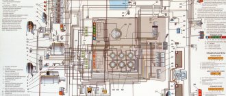
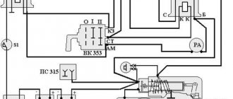
Belarus tractors are equipped with single-wire electrical equipment designed to start the engine, operate external light and sound alarms and additional components. The color diagram of the MTZ-82 electrical equipment attached to the technical documentation with a description allows you to determine the purpose of the wiring cables and restore the integrity of the circuits in the event of a breakdown.
Electrical diagram of the MTZ-82 tractor
The electrical circuit has a voltage of 12 V, the negative outputs of current sources and consumers are connected to the metal frame of the tractor. A lead-acid battery and an alternating current generator mounted on a diesel engine are used as current sources. To drive the rotor, a belt drive is used from a pulley on the toe of the crankshaft.
The generator is equipped with a rectifier unit and works in conjunction with a regulating relay, which maintains a stable voltage in the on-board network and turns off the generator winding when the tractor is idle.
On equipment assembled before the beginning of 1976, the G304-D1 installation with a power of 400 W was used. Later, G306 with similar parameters and G309, characterized by increased output up to 1000 W and an increased resource, began to be used. The generators are equipped with a self-excited winding, which allows the equipment to be operated with the battery removed. Factory documentation recommends connecting electrical equipment in series, which reduces the peak load on the generator.
What is
The diagram shows the relative positions of electrical components and connecting cables. A separate field contains a description of the colors of the insulation used to protect electrical wiring. Separate callouts explain the switching of nodes or relays, which simplifies repair work.
The tractor design uses a power switch that allows you to temporarily disconnect the batteries from the vehicle body. De-energization is used during long-term storage of equipment or during routine maintenance related to electrical circuits.
A short list of components available on the wiring diagram of the MTZ-82 tractor:
- power supplies;
- distribution box with fuses;
- control devices and indicators in the operator's cabin;
- electric starter and device control circuits;
- PD-10 gasoline starter ignition system (installed on the MTZ-82L modification);
- external lighting equipment (headlights, side lighting, stern brake signals, direction indicators);
- electric motors of the windshield wiper trapezoid, washer fluid supply pump and ventilation system;
- a plug socket that allows you to connect lighting devices on towed equipment;
- auxiliary devices (for example, a signal beacon on the roof or a lamp in the tractor cabin).
Belarus-82 tractors produced after 2010 have an additional circuit for connecting a radio receiver and loudspeakers. An additional position has been introduced into the ignition switch design, which allows you to turn on the receiver when the engine is turned off. Some machines are equipped with an air conditioner with a compressor equipped with an electromagnetic clutch. On tractors there is an electric torch engine heater equipped with solenoid valves and an incandescent coil.
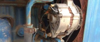
Starter MTZ-82
To start the power unit, an electric motor equipped with a retractor relay is used. The electromagnetic unit allows the gear mounted on the starter rotor to engage with the flywheel ring gear. After the engine starts running, the tractor operator releases the key in the lock, the relay automatically opens the crankshaft and the rotor of the electric motor. The large starter has a power of 4.8 liters. pp., some machines use units with planetary gearboxes, ensuring reliable diesel starting at low air temperatures.
Maintenance and repair
Maintenance of the electrical components of the MTZ-82 tractor consists of carrying out routine maintenance and checking the condition of cables, instruments and incandescent lamps. The batteries are wiped from dust and traces of electrolyte, the liquid level in the banks is checked, and recharging is performed. In the generator, the field windings are checked, as well as the rectifier unit and the windings on the stator.
The voltage regulator used on the tractor is equipped with a seasonal switch. The manufacturer recommends checking and adjusting the voltage value at the regulator output. The unit is configured on equipment or on a special stand.
The electric starter is serviced after 3000 hours of diesel engine operation. The electric motor is removed for disassembly, followed by cleaning the commutator and checking the condition of the brushes. At the same time, the condition of the electromagnetic relay and the gear in contact with the ring gear of the diesel flywheel is monitored.
During operation, contamination of the high-voltage wire running from the magneto to the spark plug is not allowed. The magneto is serviced after 960 hours of engine operation; during the inspection of the unit, the components are cleaned of contaminants and the gaps between the breaker contacts are adjusted. At the same time, the spark plug is unscrewed and the gaps between the contacts are checked.
Source
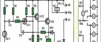
The principle of operation of the starter retractor relay at MTZ
The solenoid relay on the MTZ tractor controls the operation of the electric starter and is permanently mounted on its body.
The traction relay is a cylindrical solenoid, which is combined with a contact group. It is the retractor relay that connects the starter to the battery, and also mechanically connects the starter and the flywheel when the power plant starts.
The MTZ starter retractor relay simultaneously refers to the mechanical and electrical system of the starter, controlling their combined operation.
The main tasks of the traction relay are as follows:
- Connecting the bendix when starting the engine with the flywheel ring gear and holding it in the desired position until the ignition key is released.
- Connecting the starter motor to the battery.
- Disabling the starter when the ignition key is released.
Despite the fact that, in fact, the solenoid relay is a component of the MTZ starter, mounted on its body, the traction relay is considered an independent unit, which is responsible for the stable operation of the engine starting system.
What is an MTZ electrical circuit?
Let's look at what the electrical equipment diagram of a Minsk tractor consists of. One of the advantages of Minsk technology is the use of high-quality electrical wiring, based on the fact that metal parts are designed to act as mass. The advantages of such electrical wiring MTZ-1221, 80 or 82 include:
- reduced number of wires;
- simplified approach to maintenance.
But you need to take into account that wiring requires constant care and monitoring.
This will help monitor the serviceability of the wires, their insulation, and the reliability of the fastenings. If damage to the electrical circuit of the MTZ-80 or 1221 tractor is not detected in time, a fire, insulation damage, failure of electrical circuits, etc. may occur.
Let's look at the electrical equipment of Belarus tractors and a description of its operation.
The electrical circuit of MTZ-1221, 80 or 82 has the following characteristics:
- It has a polyvinyl chloride colored surface with low voltage.
- Additional elements are connecting panels, connectors, and wires that can be mounted in bundles. For example, such a half-move is applied to wires in MTZ-82.
- The PS 300A-100 socket is located on the rear wall of the operator's cabin and has 7 contacts.
- The socket is intended for all work where electricity is needed, including when transporting goods.
- Connection to the socket is made via a plug.
- If the need arises, you can connect the wiring harness from other units. Both the plug and the socket have special markings that help you understand where the wires are connected.
Thus, the wiring of MTZ-80, 82 and 1221 is functional and is designed to withstand loads while the tractor is operating.
How do problems manifest themselves with the starter solenoid relay at MTZ?
The traction relay is responsible for connecting the MTZ starter to the battery and starts the diesel engine. Therefore, malfunctions of this unit directly affect the operation of the tractor engine. You can suspect the presence of a breakdown based on the following characteristic signs:
- A grinding noise is heard when the starter is turned on.
The appearance of a metallic grinding sound when the starter is turned on may indicate that the traction relay and the clutch mechanism are not working correctly and their position needs to be adjusted.
- The MTZ starter solenoid relay works, but there is no rotation of the armature.
This is one of the most common failures of the traction relay. It is caused by burnout of the contact bolts.
- The MTZ starter does not turn off after starting the diesel engine.
This problem may also indicate burnt out traction relay contacts.
- Weak starter rotation when the battery is normally charged.
Diagnostics of the MTZ starter solenoid relay is usually carried out visually. The surface of the part body and contacts are carefully inspected. Traces of sintering and burning, and contamination of the terminals should alert you. Also, the traction relay “rings” for the presence of a break in the windings, an increase in the resistance of the power circuit, etc.
If quick replacement of the traction relay is not possible, turn the burnt contact bolts 180 degrees. But be sure to replace the MTZ solenoid relay whenever possible.
To exclude other damage that may give a similar picture, the battery is diagnosed.
Electrical wiring diagram of MTZ-82.1, color with description
"Belarus" MTZ-82.1 is a new universal agricultural tractor of 2006, which is a modified model of MTZ-82 and can be equipped with a hole drill, hay thrower or plow. In models produced since 2013, the chassis has been improved and a large number of attachments have been added, which can be purchased separately.
When performing electrical equipment maintenance or repairs, most often the required unit is removed or the wiring is partially disconnected; this is where you will need a schematic diagram of the electrical wiring in color, which you can view and download absolutely free!
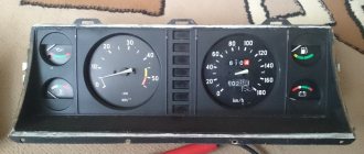
Electrical equipment MTZ-80 with a small cabin
The Belarusian tractor MTZ-80 with rear-wheel drive and a small cabin is equipped with DC electrical equipment. All devices are connected “plus” to each other according to the circuit with one wire, the negative terminals “cling” to the ground of the tractor. In the picture you see a color wiring diagram of the old 1974 model.
Let's consider its main elements:
- Battery, generator, relay regulator.
- Electric starter, torch heater and switch.
- Headlights: front and rear, turn signals with turn relays, side lights, brake lights, cabin light, light switches.
- Electric motor of the air conditioning and heating unit.
- Windshield wipers and switches with separate electric motor.
- Measuring instruments. If you did not know how to connect an ammeter to the circuit, then it is already installed between the power source and the generator.
The electrical diagram of the MTZ-82 with a large cabin, shown in the photo, helps the user understand the location of electrical equipment and the cables that connect them. Separate colored callouts decipher the purpose of a particular wire based on the color of the protective insulation.
MTZ-82 tractors with a large cabin of the new generation, which began to be produced in 2010, have some additions to the electrical circuit: a circuit for connecting a radio with the ability to turn on when the engine is not running, as well as an air conditioner with a compressor.
Connection diagram for additional headlights via relay
First of all, you need to study the headlight connection diagram via a relay shown below. This is the order in which the wires should be connected; nothing should be confused, as the light will not work.
This is the easiest option to implement; everything is simple and accessible even for inexperienced craftsmen.
The video explains the connection of additional headlights very simply.
Preparation
Since additional headlights light up more often along with the dimensions, you need to think about where it is best to connect to the on-board network. Panel lighting or any other convenient place will do. This will prevent the inclusion of dimensionless headlights, which is important according to traffic rules.
It is also worth choosing a location for the relay. Here you need to consider comfort, as well as ensure reliable fastening. There should be no moisture in the relay. Most often it is placed under the instrument panel in the vehicle interior or in a protected part of the engine compartment.
If there is free space in the relay box, you can install the element there.
What kind of lighting do you prefer?
Built-in Chandelier
It is necessary to think in advance where and how the wires will be laid. They should not protrude or droop in plain sight. It is better to connect them to the standard wiring and stretch them to prevent damage during operation of the machine.
Job
To connect the light via a relay, the easiest way is to break the process into separate steps and perform them in order:
Starter in the tractor electrical circuit
A mandatory element of the electrical equipment of Minsk tractors is a starter, which is activated by a color scheme. The starter consists of the following elements:
- Electrical engine;
- drive unit;
- relay;
- switch.
Engine power is 4.8 hp. The MTZ-82 electrical circuit ensures the operation of a starter DC motor, which is made of series excitation coils. All coils have 4 poles.
To turn on the starter, the developers installed a special switch. It is located on the control panel in the operator's cab. The engine starts due to the fact that power comes from the battery. The torque from the shaft is gradually transmitted to the crankshaft, which is associated with the operation of the drive gear with the flywheel.
How to connect to MTZ-80
The Belarus MTZ-80 tractor is equipped by default with a PD-10U gasoline starter, popularly called a “starter”. It has a significant disadvantage - the constant need for fuel. To connect an electric starter instead of a starter, you need to purchase the starter itself, the rear adapter sheet and the flywheel (or flywheel crown).
Before starting work on the replacement, study the electrical diagrams and drawings. The presented diagram shows that to connect, it is enough to connect the wire from the relay to the “plus” of the starter, and the negative terminal to the tractor body.
Gear starter for MTZ
The design of the gear unit is distinguished by the transmission of torque from the armature through a built-in gear reducer, which, with its gear ratio, increases the torque power to the diesel flywheel. This design of the unit has a smaller electric motor part, thereby reducing the cost of production of the unit. The idea of the design is to reduce the use of expensive electric steel, magnets, and copper in assembly parts during production and increase the profitability of sales.
Gear starter Magneton 3.2 kW
For the consumer, the advantage is a lower consumed discharge current and a lower voltage drop in the network during startup, taking into account the increase in power due to the mechanical part of the unit. The use of a unit of this design has a positive effect on the battery charge life, which is important when starting is difficult in the cold season.
The market offers a number of units for MTZ 82 by the following popular brands:
- Slovak - Slovakia
- Atek - Belarus
- Jubana – Lithuania
- Magneton – Czech Republic
To eliminate biased assessments in the comparison of the above brands, we will not fall into a useless assessment based on a number of reviews on the Internet. Often, buyers' impressions can be based on the purchase of counterfeit units of low quality that discredit a particular brand. To select a unit, we will indicate a number of criteria that ensure the acquisition of a high-quality starter.
Criteria for choosing a starter
Today, the qualitative differences and advantages of components of absolutely all brands are determined by the quality of assembly parts manufactured to order in China. Each brand adheres to its own marketing strategy in sales, which determines the price level, service, technical and quality level of the units offered.
Magneton gear starter device
In a market saturated with counterfeits, manufacturers are trying to improve their brand identification system to protect their reputation. When purchasing, pay attention to: the presence of branded seals and hologram stickers of the manufacturer identifying the originality, a technical passport, and a warranty service card.
One of the simplest ways to determine the quality of a knot is by weighing. If the weight of the unit is less than the value specified in the technical documentation, be sure that you are being offered a fake version. And also by comparing the quality of two units of different brands with identical power, by weighing you can determine the quality of the unit. The difference in weight indicates an advantage in the design of the unit, which is expressed in more powerful excitation windings, the width of the working part of the stator and armature, and the reliability of the gearbox design.
Gearbox and starter bendix Magneton
An additional factor in the preference for choosing a unit may be the collapsible design of the solenoid relay, which makes it possible, if the connecting contacts (nickels) burn out, to quickly fix the problem without additional time and money, freeing you from completely replacing the relay. Excitation brushes made of graphite-copper material, in contrast to simple graphite ones, have an increased service life.
Factors that reduce starter starting ability
To start the D-240 diesel engine, a starter with a power of 3.2 kW is most suitable. Many sellers offer 2.8 kW gear units for installation on MTZ 80(82), motivating buyers with price. However, as practice has shown, such power is not enough to start the tractor in the cold season. Often, additional reasons for poor starting are worn or insufficiently tuned diesel fuel. At the same time, if the starter is installed after conversion to the transmission of the removed starter, additional power losses occur due to the rotation of the gearbox parts.
Taken together, these factors negatively affect the starting ability of the starter and its working life. Therefore, to overcome the above factors, you need to install a starter with a power of at least 3.2 kW, preferably with a reinforced bendix and gearbox.
Connection diagram for generator MTZ-80
The generator on the Belarus MTZ-80 is installed as a three-phase one, in the rectifier of which the alternating current is converted into direct current. It serves as an additional source of electricity, along with batteries.
The colored electrical circuit of the generator shown in the picture with a description consists of:
- series-installed coils and stator field windings;
- rectifier unit consisting of a diode bridge;
- regulator unit with voltage switch.
Ignition switch MTZ-82 wiring diagram
The ignition switch block is installed on the dashboard and is used to start the starter of the tractor starting engine. Starts or interrupts the operation of a current-carrying circuit. Main parts of the ignition switch 2:
- a switch on which the output terminals and the main contact with the generator rotor are located;
- a lock, which in turn consists of a zinc body, retaining rings, locking cylinders and a key.
The wires must be connected according to the color diagram.
Charging circuit MTZ-80
This color diagram with a description shows what elements the charging system of the MTZ-80 tractor consists of.
- Generator, which is the main power source.
- Rechargeable lead-acid batteries act as a backup power source for the tractor engine.
- An indication lamp that lights up when the generator does not produce electric current when the ignition switch is turned on.
- A fuse box that protects an electrical circuit from a short circuit.
The generator and battery are connected with a “positive” wire, and the “minus” wire is output to the metal case.
Suspension diagram for MTZ 82
The suspension is designed to hinge the traction frame with a blade to the main frame of the motor grader and ensure its installation of the blade in various positions that are necessary for the normal functioning of the machine.
The traction frame is suspended from the main frame at three different points. One of which is a ball pin that pivotally connects both frames - this is the front suspension along the motor grader.
There is also a rear suspension, which is carried out using two hydraulic cylinders for lifting the blade, hinged to two eyes of the clamp on the main frame of the motor grader, and ball joints of the transverse beam of the traction frame.
Hydraulic cylinders can either raise or lower the traction frame depending on their activation, and they also connect both frames.
Source
Electrical circuit maintenance
Maintenance of the tractor circuit can be done with your own hands or with the help of an electrician. The main thing is that this happens regularly and that all terminals and fastenings are checked. If necessary, it is necessary to clean the necessary parts from dirt and dust.
The starter requires cleaning every 3000 hours of use. To do this you need to do the following:
- dismantle the starter;
- remove dirt;
- remove the casing that performs protective functions;
- check the brush-commutator assembly.
Then the starter must be reassembled and the insulation on the wires, the connections on the plugs, and the integrity of the wires checked.
Source