Technical characteristics of EKG-8I
| The greatest force on the bucket block | 80 tf |
| Maximum pressure force | 37-40 tf |
| Average specific ground pressure when moving | 2.08 kgf/sq.cm |
| Boom length | 13.35 m |
| Largest digging radius | 18.4 m |
| Digging height at largest digging radius | 8 m |
| Maximum digging height | 13.2 m |
| Maximum unloading height | 8.6 m |
| Body width | 6.51 m |
| Excavator overall width | 7.69 m |
| Excavator height without boom | 11.55 m |
| Track length | 8.1 m |
| Track width | 6.98 m |
| Track width | 1.4 m |
| Estimated cycle time | 26 s |
| Platform rotation speed | 2.78 rpm |
| Climbability | 12 degrees |
| Movement speed | 0.42 km/h |
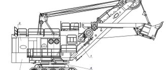
ECG-8I device
The model consists of working equipment, a rotating platform with mechanisms installed on it and a running trolley. The working equipment includes a boom, a stick, a bucket with suspension, a mechanism for opening the bottom of the bucket and a boom suspension. The articulated boom consists of a lower and upper section of a welded tubular structure. The boom takes the loads from the bucket with the handle and transfers them to the turntable and boom suspension. The handle is connected to the boom by a movably swinging saddle bearing. The bucket is suspended on a lifting rope that goes around the head blocks on the boom. The boom suspension is pivotally connected to a two-legged stand, which transfers loads from the boom to the turntable.
The rotating platform serves as the basis for the mechanisms and working equipment installed on it and, together with them, forms the rotating part of the machine. The turntable frame is also the body of the excavator's counterweight. A lifting winch, a turning mechanism, a pressure winch, a compressor, a body, and a driver’s cabin with controls are installed on the turntable.
The EKG-8I rotary platform rests on a roller circle lying on the ring rail of the undercarriage and is connected to the undercarriage by a central axle. The undercarriage serves as a support for the entire rotating part. Structurally, the undercarriage consists of a lower frame of a welded structure, a caterpillar track, running mechanisms for individual caterpillar drives and a ring gear with a roller circle. The pressure mechanism is used to impart reciprocating movement to the handle. The mechanism consists of a pressure winch and ropes. The winch is driven by an electric motor connected to the gearbox by a friction clutch of the limiting torque. Drums are mounted on the output shafts of the gearbox.
Diagram of working dimensions of the EKG-8I machine
Equipment layout diagram on the EKG-8I rotating platform
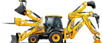
Description of ECG excavators
Excavator ECG - decoding numbers and letters. The numbers in the model names indicate the volume of the bucket in cubic meters. The number is followed by a letter index indicating the manufacturer's improvement. For example:
- letter A - indicates the first update of the model;
- the letter U is an extended piece of equipment designed for top loading;
- the letter D stands for diesel;
- the letter N is the name of the Novokramatorsky Machine-Building Plant;
- letter I - Izhora factories.
Let's look at the description of the design. The excavator is not complicated. The machine has 1 scoop, moves on tracks, and the control cabin rotates freely around its axis. The main equipment is called a mechanical shovel.
This machine has proven itself well in the quarry; it is used to develop lands of various categories. The mining and coal industries cannot do without this technology. The machine digs up the soil during mining, performs loading operations, filling dump trucks with a dump.
Types of ECG excavators and main characteristics of the equipment.
EKG-5A excavators are designed as follows.
The chassis consists of the following elements:
- frame;
- caterpillars;
- ring gear;
- travel reducer.
The hydraulic system controls the brakes and clutches.
Rotating platform on which are installed:
- driver's cabin;
- winches;
- two-legged stance;
- 2 rotary mechanisms;
- pneumatic system (controls the brakes);
- electrical equipment.
The undercarriage is supported by a roller circle.
The pneumatic system is responsible for the rotation, pressure, and lift brakes. Blows dust out of equipment. All this works using compressed air from a 2-cylinder compressor.
The hydraulic system controls the chassis brakes.
High-voltage current receiver located between the lower and rotary frames.
Brake system EKG-8I
Braking of the pressure mechanism during operation is carried out in countercurrent. To slow down the pressure mechanism when the machine is stopped and the excavator is de-energized, a pneumatic shoe brake is provided, unified with the brakes of the lifting mechanism. The lifting mechanism is used to raise and lower the bucket. The mechanism consists of a lifting winch and ropes. The winch is driven by two electric motors connected to the gearbox by two elastic couplings. Drums are mounted on the output shafts of the gearbox, on which lifting ropes are attached.
Braking of the lifting mechanism during operation is carried out countercurrently. To slow down the lifting mechanism when stopping the machine and de-energizing the machine, two pneumatic shoe brakes are provided, unified with the brake of the pressure mechanism. The rotary mechanism is used to rotate the turntable with mechanisms and working equipment. The rotation drive is carried out by two identical mechanisms, each of which consists of an electric motor and a gearbox. At the upper conical end of the shaft of each EKG 8I electric motor there is a brake pulley for a shoe brake, designed to slow down the turning mechanism when the machine is moving, when parked and during an emergency blackout, and at the lower end there is a gear, which is the drive gear of the turning gear.
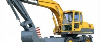
Photo source: EKG-8I The capacity of the main EKG-8I bucket is 8 cubic meters
The cantilever output shaft of the gearbox ends with a sliding gear engaged with a fixed ring gear located on the lower frame of the machine's undercarriage. The pneumatic circuit is used to control the rotation, lifting and pressure brakes, blowing compressed air onto electrical equipment and mechanisms, controlling the entrance staircase, giving a signal and driving various pneumatic tools.
The air is pumped by a compressor station, which consists of a BB-O7/8 compressor driven by an electric motor and two series-connected air collectors. Such a technical characteristic as the total volume of the air collectors is 47 liters. An air filter is installed on the suction pipe of the compressor. An oil separator with a drain valve and a check valve are installed on the discharge pipe in front of the air collector. The running gear is used to move the machine and consists of an electric motor, brake, gearbox and caterpillar final drives. The electric motor is mounted on the gearbox housing, which is attached to the tracked frame, and is connected to it by an elastic coupling, which also serves as a brake pulley for the electromagnetic brake.
What is new in the practice of domestic and foreign excavator construction for machines of this class is the installation of a separate drive on each track of the travel mechanism. The gear transmissions of all EKG 8I mechanisms are enclosed in dust-proof oil baths, and their shafts are mounted on rolling bearings. The mechanisms located on the turntable (except for the pressure one) are covered by a metal body, which is equipped with forced ventilation and internal lighting. The driver's cabin, raised above the body, provides good visibility, is spacious, sealed, and equipped with a heating, ventilation, and heated glass system.
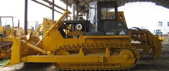
Photo source: techstory.ru Photo ECG-8I
Equipment on a turntable
Lever 8, which turns the chip and axis 7, communicates the forward movement of the chain on the bottom of the bucket, which, through a system of levers (see Fig. 8 and 9), pulls out the bolt.
A lifting winch 14, a pressure winch 13, a rotating mechanism 15, a compressor unit 16 and the electrical equipment of the excavator are installed on the turntable (Fig. 20, 21). The rotating platform rests on the running trolley through a rotating support device consisting of a gear ring, a roller circle 17 and a central axle 18.
4.2.1. The lifting winch (Fig. 22) is designed for lifting an excavator bucket using a double rope on an EKG-4u excavator (Fig. 25) or a double pulley on EKG-8I and EKG-6, Zus excavators (Fig. 24).
The kinematic diagram of the winch is shown in Fig. 23. The winch is driven by two electric motors 1. The motors are connected to the gearbox 4 by two elastic couplings 2. At the ends of the output shaft of the gearbox, drums 5 and 6 are mounted on splines. The ends of the lifting rope are attached to the drums using nuts 7 and bolts 8.
The lifting rope of the EKG-8I and EKG-6, Zus excavators (Fig. 24) is fixed at both ends to the winch drums 4 and 5, and in the middle covers the equalizing blocks of the bucket suspension 1, the head blocks 2 and 3 and the equalizing half-blocks on the lower section of the boom 6.
The lifting rope of the EKG-4u excavator (Fig. 25) is fixed at both ends to the winch drums 4 and 5, and in the middle it covers the equalizing block of the bucket suspension 1, going around the head blocks 2 and 3.
The elastic coupling of the lifting winch (Fig. 26) consists of a driving coupling half 1 mounted on the electric motor shaft and a driven coupling half 2 mounted on the gearbox shaft. Rotation from the driving half-clutch to the driven half is transmitted through rubber shock absorbers 4. The shock absorbers are kept from falling out by ring 3, secured with screws to the driving half-coupling. The driven coupling half 2 also serves as a brake pulley.
The lifting winch is braked during operation by countercurrent when the lifting control controller handle is set to the zero position. For emergency braking, pneumatic shoe brakes 3 are provided (Fig. 27 and 23), which also serve as parking brakes. The brake (Fig. 27) consists of a frame 14, two levers 5 with hinged pads 4, which cover the brake pulley. The coupling bolt 8 with the spring 9 closes the brake in the absence of pressure in the pneumatic cylinder 12. The release of the brake is performed by turning the lever 11, which, by means of the adjusting bolt 7, moves the levers 5 with the pads 4, releasing the brake pulley. The rotation of the lever 11 is carried out by the pneumatic cylinder 12 when compressed air is supplied to the cylinder. To regulate the uniform movement of the pads from the surface of the brake pulley, adjusting bolts 3 and 13 are provided.
To limit the lifting of the bucket, a lift limit switch is installed on the boom platform (Fig. 28). When pulling the bucket to the head blocks, a special stop 2 mounted on the saddle bearing presses the limit switch lever 1. The limit switch is activated and turns off the drive of the lifting winch. When lowering the bucket, stop 2 returns the limit switch lever to its original position.
The gearbox of the lifting winch (Fig. 29) is a horizontal two-stage cylindrical. The first stage of the gearbox is helical with a bifurcated power flow, the second is straight-cut. The intermediate shaft gears are cut as an assembly after they are pressed onto the shaft. To lubricate the gears and bearings, a sprinkler is installed on the drive shaft.
4.2.2. The pressure winch (Fig. 30) is designed to impart reciprocating 1 movement to the handle. The kinematic diagram of the winch is shown in Fig. 31. The winch is driven by electric motor 1. The motor is connected to gearbox 4 by elastic coupling 2.
The pressure winch gearbox (Fig. 34) is three-stage, cylindrical. The first two stages are helical, the last is straight. The second stage is bifurcated. The gear wheels of the third shaft (split stage) are cut into the assembly after they are pressed onto the shaft. Lubrication of gears and bearings is carried out by spraying oil from the gearbox bath. For this purpose, two sprinklers are installed on the drive shaft of the gearbox.
At the right end of the gearbox output shaft, a one-piece drum 5 is mounted on splines, and at the left end there is a split drum 6 (Fig. 30). In the grooves of the drums closest to the gearbox, the ends of the pressure rope are fastened using crackers and bolts, and the ends of the return rope are fastened in the outer grooves.
The reeving diagram of the pressure and return ropes is shown in Fig. 32. The return rope is passed through the return semi-block 3, the outer streams of the two-strand blocks 2, the ends are wound from above along the outer streams onto the drums 1. The ends of the rope are passed into the corresponding grooves and secured with the help of crackers 7 and bolts 8, similar to a lifting winch (Fig. 22).
The handle is moved to the rearmost position. The pressure rope is passed through the pressure semi-block 4, the internal streams of the two-strand blocks 2, the ends are wound 1.7 turns from below along the internal thread onto the drums 1. The ends of the rope are passed into the corresponding grooves and secured similarly to the return rope.
PROHIBITED:
Swap the reeving of the pressure and return ropes on the drums. Raise and lower the bucket without any clearance between the end stops of the handle and the saddle bearing, as this will cause the rope to break.
To regulate the tension of the ropes, the left drum 6 of the pressure winch (Fig. 30) is detachable.
The split drum (Fig. 33) consists of 1 pressure drum and 2 return drum. In the working position, both drums are connected to each other by a toothed sleeve 4, which meshes with the teeth on the hub of drum 1 and the ring gear 3, pressed into drum 2. To protect the ring 3 from turning, pins 8 are installed. The drums are disconnected by disengaging the gear bushings 4 using bolt 5. The head of bolt 3 is locked with bar 6 and bolt.
The elastic coupling of a pressure winch is similar in design to the elastic couplings of a lifting winch (Fig. 26). Braking of the pressure winch during operation is carried out in countercurrent when the handle of the pressure control controller is set to the zero position. For emergency braking, a pneumatic shoe brake 3 is provided (Fig. 30), which also serves as a parking brake.
The design of the brake is similar to the brakes of a lifting winch; the brakes are interchangeable in size.
To limit the movement of the handle, a command device 7 is provided (Fig. 30), mounted on racks 8, which are welded to the frame of the turntable after alignment of the chain drive 9 when installing the excavator at the customer's site. The control device is driven from the intermediate shaft of the gearbox.
4.2.3. The rotating mechanism of the excavator (Fig. 35) is used to rotate the rotating platform with the mechanisms and working equipment located on it. The kinematic diagram of the rotation mechanism is shown in Fig. 36. The rotary mechanism consists of two vertical gearboxes 9, on which one drive electric motor 8 is installed each with a brake 7 installed on the upper bearing shield of the engine.
Rotation gearbox (Fig. 35) Two-stage: cylindrical, vertical design. The drive gear 3 of the first stage is attached to the electric motor shaft with a nut, which is locked with a flange washer. The intermediate shaft 4 is mounted on spherical double-row roller bearings in the gearbox housing. Vertical output shaft 1 has one support in the gearbox housing, the second in the lower bore of the turntable housing. Both supports are made on spherical double-row roller bearings. Shaft 1 is held against axial movement by the upper support. Gear 2 is secured to output shaft 1 using a spline connection and a nut. The nut is locked with a key to prevent it from being unscrewed arbitrarily. To prevent oil leakage through the spline joint, the end of the shaft with the nut is closed with a cover with a gasket. The upper support of the output shaft has a combined seal consisting of a contact seal with round rubber rings and a labyrinth seal located above the oil level. On the spacer ring 5 of the lower support there are 4 M10 threaded holes. Before installing the gearbox on the turntable, bolts are screwed into the holes of ring 5, with which the position of the outer ring of the spherical roller bearing is verified and fixed.
Lubrication of the gearbox gears and bearings of the intermediate shaft 4 is forced liquid. The supports of the output shaft 1 and the open gear transmission of the 3rd stage (ring gear - output shaft gear) are lubricated with grease.
Each rotation gearbox has an individual pumping unit (Fig. 37) consisting of an electric motor 1 and a gear pump 2. The pumping unit is installed on the gearbox cover. Oil is sucked in from the bottom of the gearbox oil bath. Oil is pumped through pipelines 4 and 5. On pipeline 4 there is a liquid flow indicator 3.
A filter and an oil indicator are installed on frame 7.
The rotary mechanism brakes (Fig. 38) are shoe brakes, installed on the upper bearing shield of the rotation motors. Brake pulleys 6. (Fig. 35) are attached to the upper output ends of the electric motors. The design of the brakes is similar to the pressure and lift brakes, with the exception of frame 1, which is modified for flange mounting of the brake on the bearing shield of the vertical slew motor. The uniformity of the pads moving away from the surface of the brake pulley is ensured by adjusting pins 12.
4.2.4. The central axle is designed to center the rotating platform relative to the lower frame and keep the rotating part of the excavator from tipping over when digging at the maximum reach of the handle, when the resultant of the weight of all the components of the rotating part of the excavator and the digging forces goes beyond the roller circle.
The axis of the central axle 2 (Fig. 39) is installed in the central casting of the turntable frame and is secured against rotation by locking bars. The lower part of the trunnion rotates in a bushing pressed into the lower frame casting. By means of a nut 5 resting on a spherical washer 4, the axle keeps the rotating part of the excavator from tipping over. The nut is prevented from turning by locking bars 6 and rotates together with the axis of the central pin. The axis of the central axle is made hollow for routing cables from the turntable to the electrical equipment on the lower frame. The cables are laid in pipe 3, which is installed in bushings 1 and 9. To prevent rotation relative to the lower frame, pipe 3 is secured with rods 8. A ring current collector is installed on top of the flange of pipe 3.
4.2.5. The pneumatic system is designed to control the lift, swing and pressure brakes, to raise and lower the entrance ladder, to blow dust off electrical equipment and sound an alarm, and to spray lubricant on the ring gear.
A schematic diagram of the pneumatic system is shown in Fig. 40. Air is pumped into the pneumatic system by a compressor station. The compressor station consists of a compressor 2 and a drive motor 1, installed on a foundation into which series-connected air collectors 7 with a total capacity of 47 liters are welded. Compressor capacity 0.7 m3/min., operating pressure 7.5-8 kgf/cm2.
An air filter 3 is installed on the suction pipe of the compressor. An oil separator 4 with a drain valve 12 and a check valve 5 are installed on the discharge pipe in front of the air collectors. The air collectors are equipped with the necessary fittings: a safety spring valve 6, a pressure gauge 9 and drain valves 8.
From the air collectors, compressed air is supplied through pipelines through electro-pneumatic distributors 11 to the actuating pneumatic cylinders 10 of the lift, pressure, rotation and entrance staircase brakes, the sound signal 13, and also through the valve to the spray feeder 21, intended for lubrication of the ring gear.
A pressure gauge 14 and a pressure switch 15 are installed in the driver's cabin. A hose is attached to shut-off valve 19 for purging dust from electrical equipment. In the driver's cabin there is a tank 18 with water for washing the windows in the driver's cabin. The tank is connected to the pneumatic system through a throttle, which allows you to regulate the air pressure in the tank and thereby the water supply through the washing hose 17.
The electro-pneumatic distributor (Fig. 41) is controlled by an on-off type solenoid valve.
When the current is turned on, the electromagnet 7 moves the valve system 8 down, closing the hole connected to the atmosphere and connecting the compressed air line to the upper cavity of the distributor. This causes the valve system 3 of the distributor to move downwards, as a result of which air from the line passes through the lower valve into the brake cylinder. The gel distribution hole connected to the atmosphere is blocked.
When the current is turned off, the springs return both valve systems to their original position, in which the brake cylinder and the upper cavity of the distributor are connected to the atmosphere, and the compressed air line is blocked.
Pressure switch 15 (Fig. 40) is designed to automatically turn on and off the compressor electric motor depending on the air pressure in the tank. The motor control circuit is closed and opened by a moving contact. For tropical pressure switches, the contacts are located in the spark arrester chamber. The moving contact is connected to the rod, which is under the action of a diaphragm at the bottom and an adjustable spring at the top. As the air pressure in the system increases, the diaphragm overcomes the force of the spring, moving the rod upward. In this case, the device connecting the movable contact M with the rod ensures instantaneous opening of the contacts regardless of the speed of movement of the rod. When the air pressure in the line decreases, the spring moves the rod down, the movable contact instantly closes the engine control circuit.
The switch-off pressure is adjusted by tightening the spring, and the switch-on pressure is adjusted by changing the contact opening using a stop screw.
4.2.6. Grease system.
To reduce the time spent on servicing grease points and to ensure reliable lubrication of rubbing surfaces, an electromechanical solid oil blower is installed on the excavator (Fig. 42a). The pressure in the lubrication system is created by a plunger pump 5, which is driven by an electric motor 6 through a two-stage gearbox 9.
Lubricant is forced into the pump from hopper 2 using a vertical screw 3. To clean the lubricant, an easily removable mesh filter 4 is installed in front of the pump. To limit the pressure in the discharge system, a pressure switch 7 is installed, which automatically turns off the electric motor when the pressure in the system reaches 150 kgf/cm2.
When the pressure drops, the relay automatically turns on the electric motor.
The electric motor 6, plunger pump 5, filter 4 and hopper 2 are installed on the block 1, and the gear housing 9 is also attached to it.
The plunger pump (Fig. 426) consists of a lapped plunger pair and a mechanism that ensures reciprocating movement of the plunger. A ball bearing 11 is eccentrically mounted on the pump shaft 10, which with its outer race, when the shaft rotates, presses on the end of the pusher 12 and moves it in the cylindrical guide of the pump housing by double the eccentricity. The return stroke of the pusher is carried out by a cylindrical spring 13, which keeps the pusher in constant contact with the bearing race. The same spring presses the plunger 14 against the pusher. The plunger makes a reciprocating movement together with the pusher.
During the reverse stroke, the plunger, moving out of the sleeve 15, sucks through the receiving holes a portion of the lubricant coming from the hopper through the filter. During the forward stroke, the plunger, entering the sleeve, closes the holes and pushes a portion of solid oil through the ball check valve 16 and nipple 17 through the pipes.
From the solid oil blower, thick lubricant is distributed through pipes along the turntable, and is also supplied to the excavator ring gear. The pipeline has points for attaching a portable hose.
The portable sleeve ends with a special gun, which is designed to be connected to screw-type grease nipples of the “MB” type. The tip of the gun is shown in Fig. 43. Clip 1 is screwed onto the head of the screw oiler, after which the gun is turned on.
Lubrication of the engagement of the sliding gear of the rotary mechanism with the ring gear is carried out with solid oil supplied to the spray feeder from the solid oil blower. In a spray feeder, lubricant is sprayed with compressed air and applied to the surface of the teeth.
Lubricant and air are supplied to the feeder nozzle simultaneously. The shutdown is also simultaneous. The structure of the spray feeder is shown in Fig. 44.
Through nipple 4, the feeder is connected to the compressed air pipeline. From the solid oil blower, lubricant under pressure is supplied through a pipeline to hole B and moves spool 2 down.
In this case, valve 3 first opens, passing compressed air into nozzle 1, and then, as a result of further movement of the spool, channel B opens and lubricant enters the central hole of nozzle 1. At the outlet of the nozzle, atomization occurs in the compressed air environment.
4.2.7. Body, ventilation and lighting.
The excavator body is metal, welded from stamped sheets. The roof of the body is sectional and is attached to the body with bolts. The joints between the sections are sealed with quick-release cords made of profiled rubber, pressed to the roof by springs. The places where the beams of the rear pillar of the biped pass through the roof are sealed with casings. When installing the excavator and its operation, it is necessary to ensure the presence of rubber gaskets under the clamps securing the casing to the rear pillar beam, the integrity of the casing material, and the correct installation of rubber seals in order to protect the body from atmospheric precipitation getting into it and onto the electrical equipment.
The driver's cabin is ventilated by two table fans. The presence of retractable windows in the cab allows the cab to be ventilated at the driver’s request.
Fans for motors and swing generators, as well as for lifting and swing generators, are forced. Each engine and generator has a fan with an electric motor.
Fans of the engines and generators of lift and turn draw air from the body, and the pressure motor draws atmospheric air. To prevent water from entering, a guard is installed at the fan suction port. During rain and snow, the pressure motor fan must be turned off.
For ventilation of the converter unit and other electrical equipment, there are four fans installed on the roof of the body and creating an air flow to blow the electrical equipment.
External lighting of the excavator is carried out using floodlights and car headlights installed in groups on the operator's cabin, two-legged stand, protective casing, high-voltage transformer and on the turntable.
The body lighting is provided by lamps from a 220 V mains voltage. For emergency lighting, a 12 V battery is installed. To recharge the batteries, a charger is installed on the excavator.
4.2.8. Entrance staircase. The EKG-8I excavator has an entrance staircase, consisting of a fixed staircase 2 (Fig. 45) and a movable staircase 1, driven by a pneumatic cylinder.
When the machine is operating, the movable part of the ladder 1 rises. To lower the ladder, there is a special button located on the rear wall of the operator's cab, which is controlled by the excavator operator. Electrical interlocking prevents the excavator turning mechanism from turning on when the ladder is lowered. Any lowering of the ladder is accompanied by the application of parking brakes to the excavator rotation motors.
When lowering the ladder, the driver must ensure that there are no people under the lowering part of the ladder.
4.2.9. Counterweight.
To ensure normal operation of the excavator, the weight of the counterweight must correspond to the data in table. 1 of this manual. To accommodate it, special compartments are provided in the rear part of the turntable frame.
The compartments must be filled with ballast with a bulk weight of at least 3.32 t/m3 (with minimal voids).
If the compartments are filled with gravel with a bulk weight of 1.8 t/m3, concrete—1.8-2.0 t/m3 or other fillers with the same bulk weight, the seven outer tail compartments must be filled with metal scrap with a bulk weight of at least 5.5 t/m3 (diagram of loading the counterweight to the drive in Fig. 46).
A counterweight is not supplied by the factory.
After putting the excavator into operation, it is necessary to check the balancing of the rotating part of the excavator. When extending the filled bucket to 2/3 of the length of the handle, the turntable rail should not come off the rollers. Otherwise, ballast must be added until the specified condition is met.
The presence of a gap of up to 0.5 mm under individual non-adjacent rollers is not a sign of imbalance in the rotating part of the excavator.
The name, bulk weight and total amount of aggregate are entered into the excavator's logbook.
Modifications
The EKG-8I quarry crawler excavator has a number of auxiliary mechanisms that ensure repair and installation work. If necessary, the copy can be converted into an EKG-4u or EKG-6, Zus excavator. To do this, you only need to replace the working equipment (boom, arm, bucket, boom suspension). The main components are unified with the corresponding components of the EKG-4u, EKG-6, Zus excavator. Each excavator is supplied with sets of tools and spare parts. Weight of tools and accessories - 1,040 kg, spare parts (mechanical parts) - 7,400 kg, spare electrical equipment - 1,300 kg, counterweight (not supplied by the factory) - 27-33 tons.