Installation of valve overlap of the first cylinder
It's written in the instruction manual. What is necessary is to bring the piston of the first cylinder to top dead center when the valves close. This causes confusion about what needs to be done.
In fact, everything is very simple.
Installing the piston at TDC
When the piston of the first cylinder is brought to top dead center. There are two possible valve behavior options. During one work cycle, the crankshaft makes two revolutions. Accordingly, the piston approaches TDC twice. The compression stroke occurs once. Both valves are completely closed. Since it is necessary to create compression in the combustion chamber. The second time is the exhaust stroke. The exhaust valve closes at TDC after passing TDC the intake valve opens. For air intake in case of a diesel engine and fuel mixture in case of a gasoline engine.
To adjust the valves on the D260 engine, it is proposed to set the piston of the first cylinder to TDC when the compression stroke ends and the air intake begins.
In practice it will look like this. Rotate the crankshaft until the exhaust valve begins to close. The valve is closed, turn it a little more and the exhaust valve opens. Then move the crankshaft back so that both valves are closed. You can check yourself on the sixth cylinder. The piston in it will also approach the top dead center. At the moment when the piston moves upward, both valves are closed and stationary.
The compression stroke will occur in the sixth cylinder. And at this moment the valves on the sixth cylinder can be adjusted.
There is no need to remove the injectors when adjusting the valves. But it is required to bring the pistons of the first and sixth cylinders as accurately as possible to TDC.
Installation according to the mark on the pulley
To do this, there is a TDC mark on the pulley; it must be aligned with the alignment pin.
About the history of the enterprise and the MMZ D-260 engine
The history of the Minsk Motor Plant is closely connected with the history of another glorious Belarusian enterprise - the Minsk Tractor Plant. Built immediately after the Great Patriotic War, MTZ rapidly developed and increased its production. In 1960, a decision was made to build a plant for the production of diesel engines in Minsk. First of all, for the new model of the MTZ-50 tractor, in the amount of 120 thousand D-50 engines per year.
The Minsk Motor Plant was built in just over two years, on the north-eastern outskirts of Minsk between the tractor and bearing factories. Serial production of D-50 motors started at the enterprise in July 1963. Starting next year, all MTZ Belarus tractors began to be equipped with Minsk-made engines.
The first in the history of the enterprise, not a four-, but a six-cylinder diesel engine - “MMZ D-260” - was designed and built in the first half of the 90s of the twentieth century. And its mass serial production was launched in 1995. In addition to MTZ, such powerful enterprises as the Minsk Automobile Plant, the largest, Gomselmash, became consumers of these products; road construction equipment, compressor stations, etc. In 2006, the 50,000th anniversary MMZ D-260 engine rolled off the plant’s assembly line, which went to the Minsk manufacturer of road construction equipment -.
Alexander Lukashenko is a frequent guest at Belarusian enterprises, including MMZ.
In total, the list of MMZ partner enterprises, which are consumers of its products, includes 44 factories and firms. Most of them, of course, are in Russia and Belarus; Ukraine, Uzbekistan, Kazakhstan and Poland are also represented.
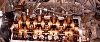
The procedure for adjusting valves on the D 260 engine
The pistons of the first and sixth cylinders are at TDC. The exhaust stroke has ended on the first cylinder. On the sixth compression stroke.
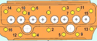
Valve numbering starts from the cooling radiator
In this position, valve clearances 3, 5, 7, 10, 11 and 12 are adjusted if counted from the radiator.
Then you need to turn the crankshaft one revolution to set the mark on the pulley to the TDC position
In this position, valves 1, 2, 4, 6, 8 and 9 are adjusted according to the radiator
Please note that the piston of the first cylinder is now at TDC on the compression stroke.
This is the easiest and most convenient way to adjust. If it is not clear and raises doubts. You can use another method. But it will be much more difficult to implement it.
Characteristics of D-260
| Production | MMZ |
| Engine make | D260 |
| Years of manufacture | 1992-present |
| Cylinder block material | cast iron |
| engine's type | diesel |
| Configuration | in-line |
| Number of cylinders | 6 |
| Valves per cylinder | 2 |
| Piston stroke, mm | 125 |
| Cylinder diameter, mm | 110 |
| Compression ratio | 15.0 17.0 |
| Engine capacity, cc | 7120 |
| Engine power, hp/rpm | 102/1800 130/2100 140/1800 155/2100 180/2100 185/2100 204/2100 206/2100 209/2100 230/2100 250/2100 280/2100 |
| Torque, Nm/rpm | 497/1500 500/1400 682/1300-1450 622/1400 690/1500 745/1500 768/1300-1575 1000/1500 808/1500 883/1300-1600 961/1500 1124/1500 |
| Environmental standards | Euro 0 Euro 1 Euro 2 Euro 3 |
| Turbocharger | TKR 7 |
| Engine weight, kg | 650 (D-260.1) |
| Fuel consumption, l/100 km (for MAZ-53374) | 24 |
| Oil consumption, % of fuel consumption, up to | 1.1 |
| Engine oil | 10W-40 15W-40 |
| How much oil is in the engine, l | 19.5 |
| Oil change is carried out, hours | 250 125 (260.4/260.7) |
| Dimensions, mm: - length - width - height | 1310 645 1021 |
| Engine life, hours - according to factory data - in practice | 10 000 — |
| The engine was installed | MAZ-101, 103, 53374, 5433, 5551 ZIL-4331 Kirovets K3000 MTZ-1221, 1522, 1523 Amkodor 224, 255, 266, 290, 332, 333, 342, 352, 681 DT-120, 75D K Combine harvesters Yenisei-1200 , Niva, KSK-100, Don-1500 LTZ-150 Tractor T-150 UES-250 |
Adjustment of each cylinder separately
To do this, move the piston of the first cylinder to TDC on the compression stroke. That is, when turning the crank, wait until the valves of the first cylinder are closed and motionless. Align the mark on the pulley with the pin. In this position, adjust the valves of the first cylinder.
The complexity of this method lies in the fact. What next is to turn the crankshaft 120 degrees. This is very difficult to determine. Of course, you can navigate by the pulley if you mark it into three equal parts. But in practice this is impossible to do, since access is limited. Unless only on a removed engine.
Why is it necessary to rotate 120 degrees? Six cylinders. To bring each piston in turn according to the operating order. It is necessary to turn the shaft two turns. That is, 720 degrees. Divide 720 by six cylinders and we get 120 degrees.
After adjusting the first cylinder, rotate the crankshaft 120 degrees and adjust the fifth cylinder.
Engine operation procedure d 260
After adjusting the fifth cylinder, the shaft is rotated again by 120 degrees (one third of a turn) and the valves of the third cylinder are adjusted. And so on according to the order of work.
Agree, the first method of adjustment is much simpler and more convenient.
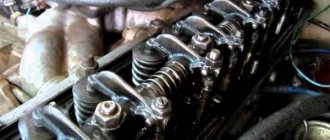
How valves are adjusted on the D 260 engine
Engine valve clearances d 260
the following are displayed:
intake valves 0.25 mm
exhaust valves 0.45 mm
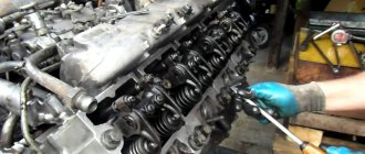
The adjustment begins by unscrewing the lock nut on the adjusting screws.
Installation of the adjustment probe
Then take a 0.25 mm probe and insert it between the end of the valve and the rocker arm. The adjusting screw is tightened so that the feeler gauge passes through the gap with little effort.
Do not tighten the dipstick too much. This may compress the valve spring. And if you manage to pull out the dipstick. Then there will be no gap. The probe should move freely with little effort.
Then the adjusting screw is fixed and secured with a nut.
On the exhaust valve, the adjustment process is the same, only a 0.45 mm thick feeler gauge is used.
Features and differences of piston diesel engines MTZ 1221
Paying attention to the diameter and stroke of the piston, we can say that these dimensions coincide with the dimensions of diesel engines D-240, D-243, D-245. However, given that the temperature and dynamic loads of the turbocharged D-260 engine are higher, the pistons of this engine have design differences.
Diesel piston MTZ 1221
For the D-260, as well as for the four-cylinder D-245, the pistons are made with an alloy steel insert for seating the upper compression ring. The insert provides the parts with high wear resistance under conditions of operation of pistons with air infusion, where the combustion temperature and pressure during operating cycles are much higher than that of a conventional atmospheric diesel engine (D-240, 243).
alloyed greasy piston insert D-260
Piston rings D-260
Also, the D-260 piston is distinguished by the presence of only two compression rings in comparison with the D-245, where the piston has three compression rings. This feature of the piston composition provides the six-cylinder diesel engine of the MTZ 1221 tractor with less resistance to crankshaft rotation, and the level of compression is achieved by a special double-sided profile of the upper compression ring.
Compression rings for piston D-260
Piston pin
In addition, piston pins of two sizes can be installed in the D-260 piston groups, where the majority of diesel engines come with a pin diameter of 38 mm, and less commonly found, a completely non-interchangeable reinforced version with a pin diameter of 42 mm.
The combustion chamber
According to the Euro classification, piston groups differ in the shape and volume of the combustion chamber in the piston.
- Euro 1 group has a small chamber installed on early versions of MTZ 1221 and 1221.2 with diesel engines D-260.2, D-260.2C, D-260.2S.
- Euro 2 with a large chamber is installed as part of the D-260.2S2 diesel engine with glow plugs on a modification of the MTZ 1221.3 tractor.
- Euro 3 with a double vortex chamber for diesel engines D-260.2S.3A(B) with increased injection pressure of the Common Rail fuel system of MTZ 1221.4, 1221.5 tractors.
- Pistons corresponding to the Euro 4 classification also have a complex vortex chamber shape and are installed on the D-260.2S.4 diesel engine of the fourth environmental level (Stage IV) under the Common Rail fuel system of the 1221.6 tractor.
Changing the combustion chamber in the piston is an evolutionary modification of the engine in terms of improving the efficiency of fuel combustion and its implementation into useful power, which also increases the efficiency and environmental friendliness of the power unit.
Valve adjustment interval on engine d 260
The valves on the D 240 engine are adjusted every 500 hours of tractor operation. The procedure is not complicated. The result is uniform and responsive engine operation. Fuel burns better. Optimal temperature conditions are maintained. As a result, the service life of the engine is significantly increased.
The unclear word valve overlap written in the instruction manual should not scare you. Just pay attention to the movement of the valves when turning the crankshaft and everything will immediately become clear.
Engine modifications for MTZ 1221
The earliest 1221 tractors were equipped with the D-260.2, D-260.2S engine, and in accordance with its technical evolution and increasing environmental standards, the following power plants are installed on later machines:
| Engine make | Tractor modification | Power hp | Environmental standard |
| D-260.2S | 1221.2 1221V.2 1221T.2 | 130 | Stage I |
| D-260.2S2 | 1221.3 | 132 | Stage II |
| D-260.2S3A | 1221.4 | 132 | Stage IIIA |
| D-260.2S3B | 1221.5 | 136 | Stage IIIB |
| D-260.2S4 | 1221.6 | 136 | Stage IV |
As mentioned above, the modification evolution of the MTZ 1221 tractor is associated with the logic of increasing the environmental standard of the tractor engine. Due to this factor, modifications of diesel engines installed on tractors differ in certain design aspects and equipment. To clearly understand the changes in the equipment of power plants from modification to modification of the MTZ 1221 tractor, we will describe specific features in the equipment of each version of the diesel engine.
Diesel D-260.2S
This power plant is standardized according to the environmental standard Stage I. The diesel engine differs from those installed back in the Soviet period on MTZ 1221 - D-260.2 and D-260.2S with an improved injection system with a pressure of 21.6 MPa, which increases the efficiency of fuel combustion in the cylinders.
Differences D-260.2S2
The engine differs from the D-260.2S by being equipped with glow plugs to facilitate starting instead of an electric torch device. For constructive placement of spark plugs and improved mixture formation, the diesel engine is equipped with pistons with corresponding enlarged combustion chambers. The injection pressure of the fuel injectors was increased to 24-25 MPa. In addition, the D-260.2S2, like all subsequent modifications, is equipped with an intercooler, which provides intermediate cooling of the air forced into the cylinders.
Intermediate cooling ensures an increase in the specific oxygen content in the incoming volume, taking into account that when the air is pumped by the turbine, it heats up as a result of pressure. Thus, the intercooler ensures that air enters the cylinders with sufficient density, which ensures more complete combustion of fuel and maximum energy release.
Diesel D-260.2S3A and D-260.2S3B
On the D-260.2S3A engine, instead of a traditional fuel system, a Common Rail accumulator fuel system with electromagnetic, electronic injection control is installed as part of the installed electronic engine control system (ECM). At the same time, the engine is equipped with pistons with a double vortex combustion chamber. The environmental level of Stage IIIA diesel is ensured by the system of afterburning of fuel in exhaust gases by partially returning the gases to the working cylinders.
Diesel D-260.2S3A with common rail injection system
The D-260.2S3B power unit, along with all the advantages of the previous diesel modification, is equipped with an SCR catalytic exhaust gas neutralization system.
D-260.2S4
The D-260.2S4 power plant of the latest modification of the MTZ 1221.6 tractor is equipped with a DOC+SCR catalytic gas neutralization system, which confirms its IV environmental level. The tractor pistons have a complex vortex combustion chamber complying with the Euro 4 standard. Electronic engine control, together with the Common Rail fuel system, is integrated into the overall integrated electronic tractor control system KESU.
| Indicators | 260.2S | 260.2S2 | 260.2S3A | 260.2S3В | 260.2S4 |
| Rated power, kW (hp) | 96 (130) | 97+/-2 (132) | 97+/-2 (132) | 100+/-2 (136) | 100+/-2 (136) |
| Specific fuel consumption, g/kW per hour | 227 | 249 | 249 | 220 | 220 |
| Maximum torque, N.m | 500 | 559 | 570 | 570 | 570 |
| Torque reserve,% | 15 | 25 | |||
| Rated rotation speed, rpm | 2100 | ||||
| Maximum rotation speed, rpm | 2270+/-50 | ||||
| Minimum rotation speed, rpm | 800+/-50 | ||||
| Unit weight, kg | 710 | ||||
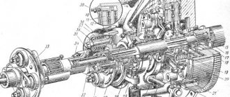
Design and basic parts of MMZ D-260
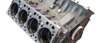
Cylinder block of the D-260 engine
The cylinder block of the D-260 engine is the main body part, made in the form of a monoblock, which is a rigid casting of cast iron. The block bores contain six removable sleeves made from a special grade of cast iron.
Each liner is mounted in the cylinder block along two centering belts. In the upper belt the liner is secured with a collar, and in the lower belt it is sealed with two rubber rings placed in the grooves of the cylinder block. Coolant circulates between the walls of the MMZ D-260 cylinder block and the liners. There are special bosses on the transverse partitions of the cylinder block, which are intended to form supports for the crankshaft. Covers are installed on these tides. The bosses together with the covers form places for installing the main bearings. The beds for the main bearing shells are bored in one installation, complete with covers. These covers cannot be swapped.
Multifunctional loader "Amkodor 332S4" with a "D-260" engine.
The MMZ D-260 cylinder block is equipped with a longitudinal oil channel, from which oil is transported through transverse channels to the crankshaft main bearings, and then to the camshaft journals and to the injectors, cooling the pistons. Piston cooling nozzles are installed in the upper part of the cylinder block, in the second, fourth and sixth crankshaft bearings. On the water distribution channel of the cylinder block there is a platform for mounting a liquid-oil heat exchanger. The supply and removal of oil from the heat exchanger is carried out through channels in the block.
To increase rigidity, the lower plane of the cylinder block is shifted downward by 80 millimeters, relative to the crankshaft axis. A steel distribution board and distribution cover are attached to the front end of the block, and a sheet of steel is attached to the rear end, through which the power unit is connected to the frame of the tractor or combine. 2 brackets, which are located on the side surfaces of the cylinder block, are also the front engine support. The bottom of the cylinder block is covered with an oil sump.
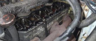
Heads in the cylinder block of the D-260 engine
The MMZ D-260 cylinder heads are cast from cast iron and are interchangeable (one head fits three cylinders). The internal cavities of these cylinder heads are equipped with inlet and outlet channels, which are closed by valves.
To ensure heat dissipation, the cylinder heads are equipped with internal cavities in which coolant circulates. The cylinder heads have plug-in valve seats. They consist of a special heat-resistant and wear-resistant alloy.
"D-260" on the next modification of the "T-150" tractor.
Three injectors are installed on each cylinder head. Also mounted here are the rocker arm axles and the rocker arms themselves, struts, head covers with caps covering the valve mechanism. To seal the connector between the heads and the cylinder block, a gasket made of asbestos-free fabric is provided. The holes for the cylinder liners and the oil channel are edged with sheet steel. Additional edging of the cylinder holes of the gasket with fluoroplastic rings is carried out during the engine assembly process.
Engine crank mechanism
The engine crank mechanism includes: a crankshaft with main and connecting rod bearings, a flywheel, pistons with piston rings and pins, connecting rods. The crankshaft “D-260” is made of steel; it has 7 main journals and 6 connecting rod journals. To compensate for the loads on the bearings from inertial forces, removable counterweights are installed on the first, sixth, seventh and twelfth cheeks of the crankshaft. Cavities are made in the connecting rod journals for additional centrifugal oil purification. The cavities of the necks are covered with threaded plugs.
Four bimetallic (steel-aluminum) half rings installed in the bores of the cylinder block and the cover of the fourth main bearing absorb the axial force of the D-260 crankshaft. The engine crankshaft is sealed with cuffs on the front and rear sides.
The following are installed on the front edge of the shaft: with interference – the timing gear (crankshaft gear) and the oil pump drive gear; drive pulley for a water pump, generator, air conditioning compressor (if we are talking about the energy-rich MTZ-1221 tractor). In order to reduce the level of torsional vibrations of the crankshaft, a silicone damper is mounted on the pulley hub.
The pistons of the MMZ D-260 engine are made of aluminum alloy. A combustion chamber is provided at the bottom of the piston. In the upper part of the pistons there are 3 grooves - compression rings are installed in the first 2 of them, and an oil scraper ring with an expander is installed in the 3rd. The hollow piston pins are made of chrome-nickel steel. The movement of the fingers along the axis in the piston bosses is limited by special retaining rings.
The connecting rod of the D-260 engine is made of steel, I-section. The bushing is pressed into its upper head. The piston pins are lubricated through special holes in the bushing and the upper head of the connecting rod. Boring of the lower head of the connecting rod for the bearings is carried out together with the cover. The connecting rod and the cap have the same numbers stamped on their surfaces. The connecting rod caps are not interchangeable.
There are also certain weight groups of connecting rods, based on the mass of their lower and upper heads. And the engine must be equipped with connecting rods of an identical weight group. Thin-walled liners for the connecting rod and main bearings of the crankshaft are made from a bimetallic strip. According to their inner diameter, the liners are made in two sizes, identical to the crankshaft journals.
The flywheel is made of cast iron and is bolted to the crankshaft flange. Steel gear rims are pressed onto the D-260 flywheels.
Gas distribution mechanism of the D-260 engine
The gas distribution mechanism of the MMZ D-260 diesel engine consists of gears, a camshaft, intake and exhaust valves, as well as parts for their installation and drive: pushers, rods, rocker arms, adjusting screws with nuts, plates, crackers, springs, struts and rocker arm axles.
The camshaft here is 4-bearing; it receives rotation from the crankshaft through distribution gears. The pushers are made of steel, with spherical bottoms, coated with special cast iron. The camshaft cams are made with a certain slope, due to which the pushers make rotational movements during operation.
Combine harvester "Polesie" with engine "D-260.4"
The push rods are made of steel rods. The spherical part that fits inside the pusher and the rod cup are hardened. The valve rocker arms are made of steel, they swing on an axis that is installed in the racks. The rocker arm axles are hollow, having 6 radial holes for lubrication of the rocker arms. The movement of the rocker arms along the axis is limited by special spacer springs.
The intake and exhaust valves on the D-260 are made of heat-resistant steel. They make movements in guide bushings that are pressed into the cylinder heads. Each valve can close under the influence of 2 springs (internal and external), fixed to its rod by means of a plate and crackers.
The valve guides are equipped with sealing collars that prevent oil from entering the diesel engine cylinders through the gaps between the valve stems and the guides. In the crankcase, which is formed by the distribution plate on the cylinder block and the distribution cover, there are distribution gears.
Power system "D-260"
The power supply system (fuel) of the D-260 diesel engine includes a fuel pump, injectors, low and high pressure pipelines, an air cleaner, intake and exhaust manifolds, a turbocharger, coarse and fine fuel filters, and a fuel tank.
MMZ D-260 diesel engines use in-line high-pressure fuel pumps (HPFP) produced by YaZDA OJSC, Yaroslavl, or Czech Motorpal. The fuel injection pump of the D-260 engine has 6 sections and performs the function of supplying strictly dosed portions of diesel fuel into the working cavities of the cylinders, for a certain time and under high pressure. The injection pump is activated from the crankshaft, through the timing gears of the D-260 diesel engine and the drive half-coupling mounted on the cam shaft.
A fuel priming pump and a rotation regulator with a boost corrector are combined into a single unit with an injection pump. The fuel priming pump is located on the high pressure pump housing. It supplies fuel from the tank to the injection pump and is driven by the eccentric of the cam shaft.
Fuel pump "YAZDA 363.1111005-40" for "D-260".
In order to remove air from the power supply system, a piston-type manual pump is mounted on the fuel injection pump. To ensure reliable and stable engine starting, the regulator is equipped with a starting device to ensure increased supply of diesel fuel during engine starting.
A bypass valve is installed in the fuel pump head, which serves to create the required pressure - 0.12...0.19 MPa, in the low pressure channels of the fuel pump. The excess volume of fuel supplied by the fuel pump is directed through the bypass valve to be drained into the tank. When the engine is not running, the bypass valve is needed to ensure the tightness of the low-pressure cavity of the pump, which is absolutely necessary for reliable starting of the engine. The fuel pump parts are lubricated with oil from the diesel lubrication system.
The injectors that are used in the D-260 for injecting diesel fuel into the cylinders are with a closed-type five-hole nozzle. These injectors provide the necessary uniform spray of fuel under significant pressure. In order to increase the reliability of the atomizer and to ensure the stability of its parameters, a gasket-screen made of a steel cage and fluoroplastic is installed under the nozzle.
The coarse fuel filter of the D-260 engine carries out preliminary cleaning of the fuel from any mechanical impurities and water. Its components are a body, a diffuser, a reflector with a mesh, and a glass with a damper. A fine fuel filter is necessary for the final purification of diesel fuel. It is equipped with a replaceable paper element. Diesel fuel, flowing through the curtains of this paper filter element, is finally cleaned of even small and minute mechanical impurities.
At the bottom of the filter housing there is a hole with a plug for draining sediment. There is also a special plug on the filter cover to remove air from the engine power system. The air sucked into the working cavities of the cylinders is cleaned by a special filter element made of paper filter cartridges, which are made of special porous cardboard. The air purifier has 3 cleaning stages. The first is a monocyclone, and the 2nd and 3rd are the main and control paper filter cartridges.
The air, under the influence of vacuum created by the turbocharger of the MMZ D-260 engine, passes through the air cleaner, cleared of dust and then entering the discharge part of the turbocharger. From there it is supplied under pressure to the engine cylinders.
Turbocharger of diesel engine "MMZ D-260"
The D-260 diesel engine uses a turbocharger that uses the energy of exhaust gases to additionally pressurize air into the diesel cylinders. Exhaust gases from the diesel cylinders are pumped under pressure through the exhaust manifold into the turbine scroll channels and rotate the turbine wheel and shaft. The D-260 turbocharger is designed according to the following scheme: a radial centripetal turbine and a centrifugal single-stage compressor.
MMZ often takes part in agricultural exhibitions and fairs in the CIS.
Engine cooling system "D-260"
The cooling system of the MMZ D-260 engine uses the principles of a closed type and forced circulation of coolant from a centrifugal pump. The rotation of the water pump is carried out using a V-belt from the crankshaft pulley. The temperature of the coolant in the system is controlled by a remote thermometer and a light indicator.
To warm up the engine faster after starting and automatically adjust the temperature at various loads, 2 “TS-107” thermostats are used, which are installed in the discharge line. Water pumps on MMZ D-260 engines are installed complete with a fan attached to a pulley.
Unit technical characteristics
The characteristics are as follows:
- The number of cylinders is six.
- The location is in a row.
- The operating order of the cylinders is 1-5-3-6-2-4.
- Cylinder diameter – 110 mm.
- The piston stroke is 125 mm.
Dimensions:
- length - 1300 mm;
- width - 705 mm;
- height - 1118 mm.
- weight - 710 kg.
Other parameters:
- Volume – 7.12 liters.
- Fuel consumption – 162 g/l.h.h.
- Power – 155 hp.
- Rotation speed - 2100 rpm, idling - 850-2260 rpm.
- Maximum torque – 622 N.m (63.4 kgf.m).
- Compression ratio – 16.