Operating principle of the PD-10 carburetor
Before starting work (that is, before turning on the engine), it is necessary to close the damper, at the same time, under the action of the control spring, another damper, the throttle, closes. After stopping the engine for a long time, you will need to pull the drowner lever. The diaphragm acts on the lever, the valve opens, and with it the passage for fuel into the chamber.
The fuel is discharged by rotation of the crankshaft, after which it enters the mixing chamber. It mixes fuel with air, resulting in a mixture that is over-enriched with oxygen. All these processes ensure immediate starting of the carburetor and engine.
After starting, the fuel loses a significant proportion of oxygen; this simple job is performed by an automated air damper valve. Gradually this valve opens wider and wider.
Carburetor operation under high loads
There are often cases in which the mechanisms experience excessive loads. So what happens in such situations in the carburetor itself?
The starting motor takes the hit first. The throttle valve opens, the degree of vacuum increases in all compartments, and fuel enters the mixing chamber. Since complex work needs to be done, more fuel enters the combustion chamber than usual. The liquid begins to discharge at the idle openings themselves, at the moment the damper opens.
Over time, the volume of fuel located in the tank cavity decreases, and the diaphragm pressure decreases. And the pressure under the diaphragm undergoes only minor changes.
A pressure difference arises, the diaphragm touches the lever, and the valve opens. The upper chamber is filled with a new batch of fuel. When there is not enough space in the tank, the pressure in both parts returns to normal and the hole closes again. This cycle can be repeated endlessly.
PD-10 starting motor power supply system
The power supply system for the PD-10 starting engine includes the following elements: fuel tank, fuel line, sediment filter and carburetor. Carburetors on the PD-10 starting engine, as well as on the PD-8, are installed in two brands, K-06 and K-16A.
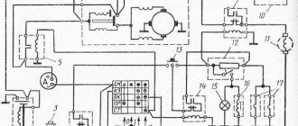
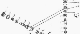
Let's consider the principle of operation of the K-16A carburetor in the starting engine. Fuel enters the float chamber (number 16) of the carburetor through a hose through a fitting (number 13) in which a filter (number 12) is installed. A constant fuel level in the carburetor float chamber is maintained using a float (number 15) and a needle valve (number 14). To enrich the mixture when starting the PD-10 starting engine, a float seal (number 11) is provided on the valve cover. The float chamber cavity communicates with the atmosphere through a hole in the chamber cover. The well (number 20) communicates with the cavity of the float chamber through a channel (number 17), and due to the main jet (number 21) and the sprayer, communication occurs with the diffuser (number 4) of the carburetor of the PD-10 starting engine. The idle jet (numbered 5), as well as channels (numbered 3 and 7), are connected by a channel (numbered 18) to the space located under the main jet. The connection between the channel (number 7) and the mixing chamber (number 10) is carried out through holes 8, in turn, the channel (number 3) is connected to the inlet pipe (number 2), the adjusting screw (number 6) allows you to change the cross-section of the nozzle idle move.
The image shows you a general view of the K-16A carburetor, as well as the designation of all its components and parts.
The structure of the inlet pipe can be described as follows: an air damper with a lever (numbered 1) is installed inside it, and the pipe itself has a cover.
A throttle valve is installed in the mixing chamber of the carburetor, which is controlled by levers. One of the levers is connected to the regulator lever with a rod. To adjust the minimum engine speed, you can use the stop screw located on the lever, which in turn is designed to manually control the throttle valve.
With the engine off, the fuel is level in the nozzle, idle passage and float chamber. During engine operation, a vacuum occurs in the carburetor diffuser, resulting in fuel flowing out through the nozzle. The formation of a combustible mixture occurs due to air passing through the diffuser at high speed and atomizing fuel.
The idle system in the carburetor is used to adjust the composition of the mixture in modes close to maximum power. When the throttle valve is fully open, and the air through the diffuser moves at an even higher speed, the diffuser discharges faster. Through the channel (number 18), air enters the space under the main jet, thereby slowing down the process of fuel flow through the main jet, which in turn does not allow the fuel mixture to become enriched.
When the engine is running at low speed, the throttle valve is only slightly open. In such a situation, the speed of air passing through the diffuser and the amount of diffuser vacuum are so small that fuel does not flow out of the atomizer. Due to the vacuum in the mixing chamber, fuel flows through channel (number 18) through the idle jet and the fuel and air entering through channel (number 3) are mixed. Further along the channel (number 7) through the holes (numbered fuel enters the mixing chamber (numbered 10) where it mixes with the main air flow. Using the idle screw (numbered 6) it is possible to adjust the composition of the fuel mixture to ensure stable operation engine at low speeds.If you turn the idle screw in, the mixture turns out to be lean, and if you turn it out, you get a rich mixture.
To enrich the mixture, when starting the engine, close the air damper, as a result of which the amount of vacuum in the diffuser and mixing chamber increases.
An analogue of the K-16A carburetor used in the PD-10 starting engine is the K-06 carburetor, which is a floatless type carburetor. Next, let's look at how the presented carburetor works. The fuel chamber is divided into two cavities by a diaphragm (number 10), and the fuel itself, passing through the fuel chamber, enters the main jet (number 6). Fuel fills the upper cavity of the fuel chamber, and air enters the lower cavity through the hole (number 11). The diaphragm (number 10) regulates the amount of fuel supplied to the fuel chamber by means of a lever (number 18) acting on the valve (number 19). When the amount of vacuum in the fuel chamber increases, then through the main jet (number 6) from the diffuser or due to the idle system, the vacuum acts on the diaphragm, as a result of which it bends and opens the valve.
The image shows you a general view of the K-06 carburetor with the designations of all its elements.
Under the influence of the spring (number 5), the valve closes when the diaphragm is lowered. On the main jet (number 6) there is a valve (number 7) with a seat (numbered) to prevent air from entering through the main jet into the fuel chamber at idle.
The diaphragm seal (number 12) serves to fill the fuel chamber during startup.
Otherwise, the operating principle and structure of the elements of this carburetor are similar to the K-16A carburetor.
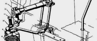
The fuel tank is attached to the jumper of the upper hood shield using brackets (numbered 1), which are welded to its body, as well as four additional bolts.
The tank body (number 4) is constructed using two halves made of sheet steel. On top of the body there is a neck for filling fuel. In the plastic cover (number 3), which buries the neck of the tank, there is a hole used for communication between the tank cavity and the atmosphere. The lid also has a sealing gasket (numbered 2), which, in turn, has a similar hole, but it is not located symmetrically with the hole in the lid in order to prevent dust from entering the tank.
This image gives an idea of how the fuel tank and sediment filter of the PD-10 starting engine are designed
The settling filter for fuel OF-150 is screwed into a barrel with a threaded hole. The bonnet is welded to the bottom of the fuel tank body. The rocker arm (number 15), nut (number 18), screw (number 17) and stop (number 16) press the filter-settler bowl (number 14) to the lid (number 9). A rubber gasket is used to seal the connection between them. The sedimentation mesh for filtering (number 6) is installed in a special connector between the glass and the lid. The valve (number 12), pressing the ball (number 10) to the lid (number 9), shuts off the fuel supply from the tank to the sediment filter. Fuel is supplied to the sediment filter when the valve is unscrewed, as a result of which the spring (number 7) presses the ball from the seat. To seal the valve, an oil seal (number 11) is used, which is tightened with a nut (number 13). The settled fuel is passed through a filter mesh (number 6) and enters the cavity of the cap, then by gravity it enters the carburetor through a rubber tube (number 19), which is placed on the tip of the cap.
Carburetor adjustments
Adjustment is made using several screws:
- Qualitative . Changes the concentration of various substances in the fuel.
- Quantitative . Regulates the amount of mixture by weight and volume. Thanks to these indicators, the engine speed changes.
- Toxic . Increases or decreases the proportion of oxygen in the fuel-air mixture.
In different variations of the carburetor, other additional screws may be present. But they all change how the engine operates at idle. It is worth remembering that idle speed itself is very unstable, which is why all these adjustment tools exist.
Adjusting the carburetor of the starter MTZ 80
If you need to adjust the MTZ 80 launcher, I recommend that you watch this video, here is an excellent starting manual carried out by professionals.
Setting the carburetor to 16 for the starting engine
If you have installed a 16 carburetor on your starting engine and need to adjust it, I recommend watching this video.
Idling
After starting the engine, the throttle valve closes under the action of the regulator , and the air valve opens. In diffuser B , the vacuum is low, so fuel does not flow from the spray nozzle. The air-fuel mixture passes into the mixing chamber through hole A , since there is a large vacuum behind the throttle valve.
The throttle valve opening value determines the minimum engine speed in idle mode.
The position of the damper and the quality of the combustible mixture are adjusted with a screw.
Features of using this type of carburetor
The operation of this engine has a number of minor differences from its “relative”. But still, taking them into account, you can make the mechanisms easier to use and minimize the likelihood of breakdown.
- Firstly, the driver completely controls the operation of the engine; PD 10 does not have an electronic unit that can regulate and configure the operation of the carburetor without the influence of the car owner.
- Secondly, not in all cases it is possible to sharply increase speed and gain power.
- And finally, thirdly, every 38,000-40,000 km. After kilometers traveled, it is advisable to disassemble and clean the carburetor.
Yumz launcher carburetor adjustment
Checking and adjusting starting devices of a caterpillar tractor.
Caring for the power system. After parking the tractor for a long time (more than 5 days), before starting the starting engine, you need to drain the fuel mixture, mix it thoroughly and pour it back into the tank. The use of gasoline without oil in PD-10U and P-350 engines leads to their premature failure.
Before refueling the fuel tank, clean the filler neck and filler cap from dust and dirt. The clogged hole in the lid is cleaned with wire.
During maintenance No. 3, the fuel tank, fuel line and sediment filter are washed, having previously removed them from the tractor. To wash the tank, fill it with gasoline of volume V3 and, shaking, wash the tank in several stages. Disassemble the sump and wash its parts in gasoline.