The crane beam is one of the auxiliary devices that are used to support the production process both in various industrial buildings and structures (production workshops, warehouse complexes) and in open areas (loading and unloading terminals, industrial sites of enterprises, storage areas).
Structurally, these auxiliary devices have two types - suspended and supporting.
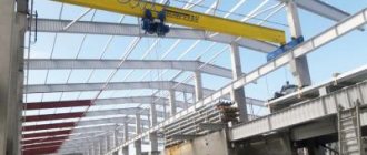
Types of support crane beams
Based on the type of movable supporting structure, they are divided into the following types:
- Single beam. In this case, the span consists of one I-section profile. The single-beam system has a small load capacity (up to 10 tons), since the working part (telpher) is suspended from the span profile and moves along its lower flange.
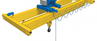
- Double beam. With this option, the span structure consists of a pair of I-beams or two box-section profiles. With a double-beam design, in most cases, the hoist moves along the upper flanges of the supporting structure, which provides higher load-carrying capacity, but its own weight is much higher.
According to the control principle:
- Stationary, when the control panel is located in the operator's cabin, fixed directly to the moving part, and moves along the service area along the rail track together with the running trolleys.
- Remote, when the control panel is presented in the form of a multi-button post on a flexible cable.
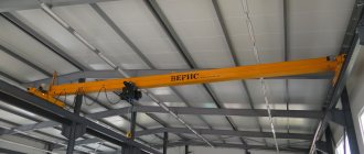
Unlike the suspended version, support crane beams have higher load capacity and speed of movement around the workspace.
When using this option, a large lifting height of the load is ensured, which is essential if the workshops or warehouses contain equipment whose height is significant, or the height of the storage systems of the warehouse complex is designed with maximum use of the building space in the vertical plane.
Such auxiliary systems can be equipped with various lifting devices: a cargo hook, a grab, a stacker, a magnet, as well as various traverses for gripping and moving similar structures or containers.
Installation
Installation of a double-girder overhead crane is carried out taking into account the following indicators:
- Technical characteristics of the crane (weight, maximum lifting height, overall dimensions, installation diagram).
- The dimensions of the room or workshop, the load-bearing capacity of the walls or columns on which they will be installed.
- Conditions for assembling the structure (availability of access roads and installation site).
There are several methods for assembling a crane. Single-beam lightweight structures are mounted below. Then the finished structure is lifted up using auxiliary equipment and installed on the rails. Installation of the structure involves a large number of operations, especially when assembling devices with a load capacity of 50-100 tons and above.
Installation stages of a double girder crane:
- Half-bridges are being installed. At the assembly site, 2 halves of the bridge are assembled.
- The end beams are assembled and installed on the crane runway.
- The half-bridges are lifted and installed on the ring beams.
- Half bridges and end beams are connected to each other.
- The trolley movement system is being installed. Then they lift it and fix it on the bridge.
- The power supply unit and the device control system are assembled.
- Install the limit switch.
- Assemble and install the operator's cabin.
- Carry out adjustment work. Test the installed lifting device.
Main structural elements
The electric crane beam (support) consists of the following structural elements:
- working body (telpher) – consists of an electric gear motor and a cable drum;
- device movement mechanism – ensures movement of the carriage across the working area (perpendicular to the rail track). It consists of an electric motor and a reduction gearbox that transmits torque to the drive rollers in a single-beam system or to the wheels in a double-beam system;
- the span is the structure along which the working part moves. This element of the lifting device is fixed to supporting elements;
- running bogies are supporting elements on which the span is fixed. They are located on both sides of the span and ensure the movement of the electric crane beam along the working area on rails located on separate supports or on consoles of columns that make up the load-bearing frame of the building (structure);
- electric drive - carried out by an electric motor, through a reduction gearbox, transmitting torque through a reduction clutch to the drive wheels. The use of couplings ensures a smooth start. The drive can be one-sided or two-way, depending on the size of the span, and is equipped with an electric brake that is automatically activated to stop the supporting crane beam, eliminating inertial movement;
- control panel - located either in a stationary cabin for the operator and equipped with the necessary buttons and levers (joysticks) responsible for a particular operation, or presented in the form of a multi-button post on a flexible cable, in this case the operator is at the bottom and follows the load being moved.
Price of a suspended electric two-span single-beam crane (without electric hoist)
Characteristics and drawing of a two-span suspended crane beam
Load capacity 1t
- Travel speed: 20 m/min;
- Operating mode: A3 (ISO 4301);
- Ambient temperature: from –20° to +40°С.
Additional options for the basic hoist package:
- Explosion-proof design;
- Fireproof design;
- Ambient temperature environments from –40° to +55°С;
- Operating mode A4, A5 (ISO 4301);
- A frequency converter;
- Soft start device;
- Travel brake;
- Radio control;
- Imported gear motors.
Operational safety
In order to ensure the safe operation of electric beam support cranes, each drive element is equipped with limit switches (limit switches):
- there is a limit switch on the cable drum that turns off the load lifting drive when the driven unit reaches the critical upper lifting point;
- on the hoist movement mechanism there are limit switches that turn off the power supply to the load carriage movement drive when it reaches the extreme left or right position;
- Limit switches are installed on the running trolleys. They turn off the drive of movement of the entire mechanism along the crane track when it reaches the front or rear end of the rail track.
stacker - features of overhead and rack cranes
What is a stacker crane?
The stacker crane got its name from another device - a stacker - transport equipment for workshops and warehouses, the purpose of which is to move different types of cargo around the production site, move them up and down the racks, as well as in mixed directions
The task of a stacker crane is the same, but its important difference is the presence of a crane mast. In addition, unlike the main device - a stacker, a stacker crane is less mobile, but is not inferior in lifting capacity and can raise the traction to a maximum height of up to 40 meters or more
Load-grabbing devices on stacker cranes can be fork-type, pin-type, telescopic or in the form of loading platforms. This type of crane can be controlled from the floor or from the driver’s cab. The stacker crane is considered primarily a warehouse equipment; with its help, the storage process is simplified, working time, labor costs and space on site are saved.
What types of stacker cranes are there?
Stacker cranes are divided into two types - rack and bridge.
- Overhead stacker cranes are equipped with a column that is attached to a trolley moving along the bridge. An overhead stacker crane is more mobile than a rack crane. His tasks include moving cargo along racks located in different places in the same room, as well as stacking cargo. An overhead stacker crane can perform various manipulations with cargo. Depending on the requirements of the technological process, these types of cranes are equipped with different types of load-handling devices, so that the crane can perform differentiated manipulations - turn over cargo, empty containers, transfer them from one place to another.
- Rack stacker cranes. Their tasks include working only in the opening between two racks. They move along rail guides and are controlled from the operator's cabin or remotely. The main difference between rack stacker cranes and bridge cranes is that the column attached to the trolley moves not along the bridge, but along the crane tracks. Rack stacker cranes can only stack loads on the two racks between which they are installed. The task of rack cranes is not to move cargo around the warehouse, but to automate the process of stacking it. It saves space in the warehouse and automates the warehousing process.
How does a stacker crane work?
The technical design of stacker cranes partly depends on their functional purpose, and also, in particular, on the type of cargo and the characteristics of the room in which it will work. Overhead stacker cranes have a number of common elements, including:
- A bridge that moves on suspended or supporting tracks;
- A trolley, which in turn moves across the bridge. It can also be suspended or supported. The task of the trolley is to carry the turntable on which the column is fixed;
- Rotating platform;
- Column. It is used to move a forklift equipped with different types of grippers depending on the type of cargo.
One of the key mechanisms of a stacker crane is a trolley and a rotating device, which carry out the main work of manipulating the load. Their movement is carried out using asynchronous electric motors, a gearbox, brakes and a steel rope acting as a load-bearing body.
How does a stacker crane work?
The work of a stacker crane begins with the capture of cargo packed in containers from the floor or from a vehicle. The crane grabs containers using different types of load-grasping devices, depending on the type of cargo. The most common type is a fork grip. The operator operating the crane lifts the load a short distance from the floor, then the stacker crane trolley is activated and moves to the place where the load needs to be delivered. Having reached the desired passage, the trolley stops, and after that the entire crane bridge begins to move along the crane tracks, moving the crane column to the place on the rack where the load needs to be installed. At the indicated location, the crane stops and the lifting device begins to move upward to the required cell of the rack, where the load should be placed. Having reached the desired cell, the trolley moves the fork, which pulls out the load and places it in place.
Important Characteristics of vehicles based on the ZIL-433362 universal truck chassis
The storage height of stacker cranes depends on their design and load capacity. Overhead stacker cranes can stack cargo to a height of 10-12 meters, while rack cranes can rise even higher - up to 30 meters and above. The lifting capacity of stacker cranes usually varies between 1-12 tons.
Manual overhead cranes with a lifting capacity of 1000 kg (KPR-1.0)- A single-girder manual overhead overhead crane (manual overhead crane) is designed for lifting, lowering and horizontal movement of cargo. The crane moves along two tracks from the I-beam. The movement of the crane is carried out by vertical movement (pulling) on an endless (connected in a ring) round-link welded chain.
- Single-beam manual overhead cranes (beam cranes) KPR with a lifting capacity of 1, 2, 3.2, 5, 8 and 10 tons are produced by SVPC in accordance with GOST 7890 “Single-beam overhead overhead cranes”, PB 10-382-00 “Rules for the design and safe operation of load-lifting cranes" and TU 3159-016-12573741-2012.
- The beam crane (manual overhead single-beam overhead crane) consists of a load-bearing beam (1), an end beam (2), an end hinge beam (3), a drive (4), a hoist (5), a drive trolley (6), a non-drive trolley ( 7), bracket (8).
- single-beam manual overhead overhead cranes produced by SVPC of all lifting capacities are reliably and efficiently painted, which protects them from corrosion for many years, even in conditions of year-round outdoor use.
- Installation, start-up, and regulation of the crane must be carried out in accordance with the requirements set out in the attached passport and operating manual for the single-girder overhead manual bridge crane.
- The manual beam crane is not intended for transporting people, molten and hot metal, toxic substances, for working in an explosive environment, for operation in a room with vapors of acids and alkalis, the concentrations of which cause corrosion of the crane structure.
- The crane is shipped mothballed, disassembled. Large parts of the crane are supplied without packaging (end beams, span beams). The figure shows the composition of the shipment (from top to bottom, from left to right): load-bearing beam (span) without packaging, end beams - 2 pieces without packaging, trolleys - 4 pieces in 2 boxes, manual hoist - 1 piece in a box. The manual hoist can be supplied in a cardboard box.
- To ensure the normal, trouble-free functioning of the components and parts of the crane, the owner must provide an appropriate maintenance system during operation.
- When operating a manual beam crane, you must be guided by the crane's passport and operating instructions, as well as the Rules for the design and safe operation of load-lifting cranes.
- The warranty period is 24 months from the date of commissioning of the crane, but not more than 30 months from the date of shipment from the manufacturer. The service life with 1.5-shift operation in passport mode is 20 years. Lifetime before the first major overhaul is 8 years.
The end beam (2) is a welded metal structure, which, with its shape, ensures a minimal vertical approach. Equipped with two trolleys: driven (6) and non-driven (7). The supporting beam of the crane (1) is bolted at one end to the middle part of the end beam (2). The other end of the supporting beam is supported by a hinge device on the middle of the hinged end beam (3).
On the brackets (8), which are installed on the supporting beam, there is a shaft with a chain sprocket (4), which is connected to the drive wheels of the drive trolleys. An endless (circular) chain (30) is thrown over the sprocket. The operator pulls the chain and the crane moves along the crane runway. The hoist, which serves to lift and move the load, is installed on a supporting beam.
The design of the hinged end beam (3) is similar to the end beam (2), only it is connected to the span beam by means of a grab. The scaffold is equipped with rollers on which the span beam rests with its upper flange. The movable connection of the span beam with the end beam makes it possible to compensate for inaccuracy in the installation of crane runways and makes the structure statically determinable. The span (bearing) beam has a different design depending on the span of the crane to ensure the necessary rigidity and strength of the crane.
Manual overhead crane: main dimensions
Designation
| Dimensions, weight (without hoist) | |||||
| Lpr, m | Lк, m | L, m | h1, mm | Weight, kg | |
| KPR-1.0-3.6-3.0* | 3,0 | 0,3 | 3,6 | 270 | 150 |
| KPR-1.0-4.2-3.0* | 3,0 | 0,6 | 4,2 | 270 | 160 |
| KPR-1.0-4.8-4.2* | 4,2 | 0,3 | 4,8 | 270 | 175 |
| KPR-1.0-5.4-4.2* | 4,2 | 0,6 | 5,4 | 270 | 185 |
| KPR-1.0-6.6-6.0 | 6,0 | 0,3 | 6,6 | 290 | 236 |
| KPR-1.0-7.2-6.0 | 6,0 | 0,6 | 7,2 | 290 | 248 |
| KPR-1.0-8.1-7.5 | 7,5 | 0,3 | 8,1 | 330 | 298 |
| KPR-1.0-8.7-7.5 | 7,5 | 0,6 | 8,7 | 330 | 310 |
| KPR-1.0-9.3-7.5 | 7,5 | 0,9 | 9,3 | 330 | 327 |
| KPR-1.0-10.2-9.0 | 9,0 | 0,6 | 10,2 | 330 | 386 |
| KPR-1.0-10.8-9.0 | 9,0 | 0,9 | 10,8 | 330 | 405 |
| KPR-1.0-11.4-9.0 | 9,0 | 1,2 | 11,4 | 330 | 420 |
* In versions with a span length Lpr of 3.0 and 4.2 meters, the manual drive shaft for moving the crane beam has one support bracket from the load-bearing beam.
In Fig. on the left is a chain sprocket and shaft mounted on a bracket. On the right is a drive trolley mounted on the end beam.
Manual suspended cranes: main characteristics
| Characteristic | Meaning |
| Type of crane runway according to GOST 8239 | I-beam 18, 20, 22, 24, 27 |
| Type of crane runway according to GOST 19425 | I-beam 18M, 24M, 30M |
| Crane classification (mode) group according to GOST 25546 (ISO 4301/1) | 1K (A1) |
| Climatic performance | U, TU and T |
| Accommodation category according to GOST 15150 | 2 and 3 |
| Group of classification (mode) of the crane movement mechanism according to GOST 25835 (ISO 4301/1) | 1M (M3) |
| Group of classification (mode) of hoist mechanisms according to GOST 25835 (ISO 4301/1) | See hoist passport |
| type of drive | Manual |
| Control system | Manual |
| Control place during operation | From the floor |
| Ambient temperature during operation, degrees C | plus 40/minus 40 |
| Relative humidity | 80 % |
| Traction force of crane movement, N, no more | 100 |
| Lifting traction force, N | see manual hoist passport |
| Traction force of hoist movement, N | see manual hoist passport |
| Lifting height, m | see manual hoist passport |
>>Return to previous page “Manual overhead cranes”
Characteristics
Since the main purpose of the mechanism is to move heavy objects, the main technical characteristic is the load capacity. The maximum lifting capacity of a crane directly depends on its design.
Crane beams also differ in the technical characteristics given below.
- The span length of the working area can be 3–28.5 m. The crane can be single-span, with a working space of 3–15 m. Or double-span, with a track length of 7.5–12 m.
- The lifting height, depending on the type of crane, can be 6–36 m for a suspended structure and 6–18 m for a supporting structure. Custom-made support mechanisms are capable of lifting loads to a height of up to 36 m.
- Voltage. All electric cranes operate from a three-phase current network of 380V (50 Hz). The current is supplied through a flexible wire.
- Speed. Depending on the type of crane, the operating speed can range from 0.4 to 1 m/s for a supporting structure and 0.5 m/s for a suspended structure.
- Temperature conditions. All types of devices are designed to operate uninterruptedly in different climatic conditions. The temperature range is from -20°C to +40°C.