Reasons for adjusting valves on KAMAZ vehicles
Before you begin adjusting the valve clearances, you need to identify and eliminate the causes that led to the malfunctions. The reasons are divided into technical and operational. Technical reasons include poor quality maintenance:
- untimely repairs;
- incorrect valve clearance adjustment and incorrect tightening of the cylinder head bolts after previous maintenance;
- wear and breakdown of gas distribution mechanism parts;
- deterioration of the quality of the coolant, resulting in insufficient engine cooling;
- dirt getting into the air tract with the intake air;
- untimely replacement of oil and oil filter, oil contamination;
- incomplete combustion of fuel.
Incorrect operation: engine overheating, prolonged operation at high speeds, frequent use of ether to start the engine - also leads to similar breakdowns.
Why does valve imbalance occur?
It is necessary to realize that adjusting KAMAZ valves with your own hands is useless if the original cause of the malfunction is not eliminated. Possible causes are breakdowns that are associated with improper or not carried out on time maintenance:
- incorrect setting of valve clearances or incorrect sequence of tightening bolts on the cylinder head during preliminary engine maintenance;
- physical wear or malfunction of timing parts;
- the use of low-quality cooling fluid, which led to overheating of the engine;
- a faulty air filter that allows not only air but also dirt to enter the cylinders;
- the use of contaminated or low-quality motor oil, untimely replacement of the filter or the oil itself;
- fuel that does not burn completely due to other breakdowns or poor quality of the fuel itself.
The procedure for adjusting KamAZ 740 valves
Correct adjustment of the valves of the ZMZ-402 engine
Correct adjustment of the valves corresponds to the order of their movement in the engine. In most KamAZ 740 engines, it is carried out at intervals of 60 degrees. To do this, you need to rotate the crowbar to 2 piston positions. In this case, the crankshaft rotates 1 revolution, that is, 180 degrees. In most models, adjustment occurs sequentially in pairs in the following cylinders:
- first and fifth;
- second and fourth;
- third and sixth;
- seventh and eighth.
Some engine models may differ from the standard design. Before starting the operation, you need to look at the documentation for the motor, namely the adjustment sequence diagram for this model. In addition to the valve sequence, they indicate the optimal clearances and pressure on the nuts. In some engines, instead of the usual for KamAZ, 0.3 and 0.4 mm. The values indicated are 0.25 and 0.35 mm. In addition, the documentation indicates the optimal tightening values for valve screws and cylinder head fastenings. For different engine models they differ depending on the mass and volume of the power unit.
Along the way, during operation, you can check the condition of the engine parts, clean the external parts and trays of dirt.
After all necessary operations have been carried out, it is necessary to check the fasteners. Next comes the running-in of the car. Engine noise, engine power, fuel consumption are checked. With proper adjustment, all these indicators should be normal, which will increase the efficiency of the machine and reduce its wear.
How to understand that you have adjusted it correctly
With correctly adjusted valve elements, the marks on the intake and exhaust camshafts are located opposite each other and are in one straight line.
You can check the correctness of the set gaps using special probes. To do this you need:
- Insert the feeler gauge between the base of the rocker arm and its end.
- At the intake camshaft, the 0.3 mm thick feeler gauge should enter with force.
- At the exhaust camshaft, the dipstick, whose thickness is 0.4 mm, should enter with little effort.
- Start the engine and check the operation of all systems.
If the valves are adjusted correctly, there will be no extraneous noise when the engine is running.
Design features of the valve mechanism
Adjusting valves d 240 in two steps
In principle, for the engine to operate, at least two valves are required for each working cylinder. One is responsible for the intake, and the second for the exhaust (the first has a larger plate diameter to ensure better filling of the working cylinder with the finished mixture). The mechanism also includes the following components:
- bushings (serve to maintain the direction of movement of the working valves during operation and prevent them from being pulled to the side);
- spring (necessary to return to its original position);
- pusher (serves to transmit pressure from the camshaft cam);
- valve stem seals (necessary to prevent engine oil from entering the working cylinder);
- crackers (serve to fix the knot and provide a supporting surface);
- seat (the place where the plate touches the engine body).
Engine Mercedes-Benz (Daimler) OM 457 LA
Purpose, adjustment, repair and replacement of VAZ 2101 engine valves with your own hands
When developing a new tractor, the most powerful engine installed on the Axor was taken as a basis - a unit of 428 horsepower.
Characteristics of the KAMAZ 5490 engine
- Six cylinders arranged in a row,
- Volume - 11.97 liters,
- Maximum torque - 2100 Nm,
- Electronic turbocharging system with intercooling of charge air,
- BlueTec system, which reduces NOx emissions and reduces the share of harmful substances in the exhaust,
- Compliance with Euro 5 environmental class standard,
- Circulating cooling with coolant,
- 4-stroke direct diesel injection,
- Cylinder diameter - 128 mm,
- Piston stroke - 155 mm,
- Coolant filling volume without recooling - 15 l,
- The volume of engine oil to be filled, including the oil filter, is minimum 34 liters, maximum 39 liters.
Operation of the KAMAZ 5490 engine
The engine is paired with a sixteen-speed synchronized manual transmission (manual transmission) ZF 16S-2221 with remote control, which allows the car, according to the owners, to be truly “powerful and torquey.”
The maximum speed of the car is stated to be 110 km/h, and the engine can withstand this maximum 110 km/h on a good road with a bang, say car enthusiasts. Fuel consumption averages 33 liters per 100 km; according to reviews, this figure corresponds to reality - from 30 to 36 liters, depending on the load.
There is no need for mandatory adjustment of the KAMAZ 5490 engine valves for the first two hundred thousand kilometers. The Kama plant began producing regulation tools well in advance of release.
Checking the oil level, replacing it, replacing filter elements - air and oil - everything happens reliably on time. According to reviews from owners, if you follow the operating recommendations, there is no need to carry out these procedures more often.
KAMAZ 5490 engine spare parts
Drivers who had to look for spare parts for a new long-haul tractor managed to appreciate the uniqueness of the truck - the arrival of important and sometimes even the most insignificant parts from the production site can take quite a long time. Reviews about this problem have already filled the forums of car owners.
The AUTOALFA group of companies offers to speed up the process of obtaining spare parts with the help of large warehouse stocks, as well as official dealership of a large group of companies that produce spare parts for the KAMAZ 5490 engine.
This group includes the main manufacturer Daimler AG and other German companies:
Spare parts from imported companies from other countries are also available:
And world-famous manufacturers of filter elements MANN+HUMMEL and Fleetguard, Inc.
KAMAZ-5490: a star has risen in the East
The new KamAZ-5490 truck tractor with a modified cab and Mercedes-Benz engine, produced in Naberezhnye Chelny, went on sale in the spring of 2014 at a price of RUB 2,700,000. If you hear that KamAZ-5490 is a Mercedes-Benz Axor, but assembled in Tatarstan, do not believe it. These are different cars, although they have many similar units.
For the first time, KamAZ has a comfortable and spacious cabin. External width - 2300 mm (excluding mirrors and wings), length - 2250 mm, internal height from floor to ceiling - 1510 mm (low roof option).
Among the priority developments of the Kama Automobile Plant is the creation of long-haul truck tractors for road trains of the European design: a two-axle tractor and a three-axle semi-trailer (coupling with a gross weight of 40–44 tons and a length of 16.5 m). The premiere display of this KamAZ-5490 took place at the Comtrans exhibition in 2011. At the beginning of 2014, the car was put on the assembly line.
If you hear that KamAZ-5490 is a Mercedes-Benz Axor, but assembled in Tatarstan, do not believe it. These are different cars, although they have many similar units. And the production areas are geographically separated. The Kamaz tractor is assembled on the modernized main KamAZ conveyor, to the trunk of which another branch has now grown, and the Chelny Mercedes-Benz Axor is assembled in the Master technology park, at the production site of Mercedes-Benz Trucks Vostok OJSC.
Seat "Grammer" assembled in Elabuga - with a lot of settings. It is comfortable to work on it because it is mounted on an adjustable air suspension.
Seat "Grammer" assembled in Elabuga - with a lot of settings. It is comfortable to work on it because it is mounted on an adjustable air suspension.
It’s okay that KamAZ got the cab from the Aksor, produced since 2001. Against the backdrop of the usual domestic one, it looks like it’s from the future. Kama engineers did a good job with it, and the designers managed to give the rather ordinary appearance of a German truck for interregional transportation the stateliness of a full-fledged flagship tractor.
The KamAZ-5490 cab has original lower panel of the radiator grille, bumper, running boards, and fenders. Material: non-corrosive plastic, high quality and durable. The bumper and running boards are mounted higher than those of a Mercedes. The German cab is attached to the frame on spring struts, while ours is mounted on a four-point air suspension, which is softer.
There are two berths in the back. Free admission. The width of the bottom shelf is 685 mm, and the top one is 700 mm. Here you can comfortably stretch out even if you are two meters tall.
There are two berths in the back. Free admission. The width of the bottom shelf is 685 mm, and the top one is 700 mm. Here you can comfortably stretch out even if you are two meters tall.
Our own lighting technology. The series included an option with small Hella lensed headlights and LED turn indicators and side lights. A little later, rectangular block headlights will appear, no worse in design and radiance than those of high-quality foreign cars.
The cabin is welded (from imported stamping), painted and assembled here. Luxurious chairs are brought from Yelabuga. The famous German company Grammer settled there. All other interior details are no different from those on the purebred Aksor - they are delivered from abroad.
In the engine compartment
Another important strategic direction for the development of the new range is the use of imported engines, although KamAZ is not going to curtail its production of diesel engines: native engines will be modernized even more deeply.
KamAZ-5490 forms a new family of trucks from Naberezhnye Chelny. These are primarily long-haul tractors with semi-trailers, followed by chassis with superstructures.
KamAZ-5490 forms a new family of trucks from Naberezhnye Chelny. These are primarily long-haul tractors with semi-trailers, followed by chassis with superstructures.
For now, the KamAZ-5490 truck tractors are equipped with the well-known in Russia in-line sixes, the Mercedes-Benz OM 457 LA, with a displacement of 11.97 liters. They are assembled at a motor plant in Mannheim. The German turbodiesel is very economical, the declared resource is one million kilometers, and the service interval is 80 thousand.
The design of the OM 457 LA is traditional: turbocharging, intercooling, camshaft in the block, wet liners, separate cylinder heads, four valves. Fuel equipment - PLD. These are individual, electronically controlled mini-fuel injection pumps for each cylinder. Euro 5 standards will be met thanks to BlueTek technology (using urea solution).
Of the three possible power and torque settings, KamAZ chose the maximum: 428 hp. and 2100 Nm. The goal is to equalize the car’s chances in competition with foreign cars.
KAMAZ-5490: a star has risen in the EastKAMAZ-5490: a star has risen in the East
But the budget version of the tractor will be equipped with an eight-cylinder KamAZ-740.73-400 engine with common rail fuel equipment, Euro-4 toxicity level, and a power of 400 hp. and torque 1764 Nm.
Will be shown on the show
Nowadays, all heavy Kama trucks are equipped with 16-speed ZF gearboxes manufactured at the CF Kama joint venture. So the KamAZ-5490 is equipped with a 16-speed ZF-Ecosplit. The German Axor uses a Mercedes gearbox, but the ZF is no worse: DAFs, MANs and Renaults are equipped with units of the same design. The options include an “automatic” AS-Tronic: this is a 12-speed automated gearbox.
The next successful solution is the use of a Mercedes drive axle, which is known from the Aksor and Aktros. It has a hypoid gearbox with a gear ratio of 3.077. There is a differential lock.
Adjusting Cummins engine valves on a Kamaz vehicle
Although the Cummins engines that power Kamaz vehicles today are highly reliable and have a long service life, they certainly require regular maintenance
Among other things, it is very important to periodically adjust the valves. According to the manufacturer's official instructions, this procedure should be performed at least every 240 thousand
km run. However, in addition to scheduled work, the need to adjust the valves may arise for other reasons.
The first signs that may indicate the need for adjustment are extraneous metallic knocks that appear in the engine compartment, an increase in the “appetite” of the power plant, or a decrease in its power. If you ignore these symptoms and do not adjust the valves in a timely manner, then further operation of the engine can cause a cascade of new breakdowns in the internal combustion engine.
Causes of valve imbalance
It is important to understand that adjusting valve clearances will be a useless exercise if the original cause of the problem is not eliminated. Technical reasons include breakdowns associated with poor quality or untimely maintenance:
- incorrectly set valve clearances or incorrect sequence of tightening bolts on the cylinder head during previous engine maintenance;
- physical wear or breakdown of timing elements;
- the use of low-quality coolant, which caused engine overheating;
- a damaged air filter, allowing dirt to enter the cylinders along with air;
- use of contaminated or low-quality motor oil, including due to untimely replacement of the oil filter or the oil itself;
- partial failure of fuel combustion due to other breakdowns or poor quality of the fuel itself.
Operational reasons include overheating of the power plant, excessively long operation at high speeds, and abuse of ether during winter engine starts.
Adjustment procedure
First of all, it should be warned that all valve maintenance work is carried out exclusively on a cooled engine, that is, when the temperature of the liquid coolant does not exceed 60 degrees.
To get to the valves, you need to remove the engine cover and the gasket underneath. The next task is to turn the crankshaft so that the piston on the first cylinder is at its top dead center. Once the crankshaft is in the correct position, begin measuring the clearances on the following valves:
- in 4-cylinder engines - 1I, 1E, 2I and 3E,
- in 6-cylinder engines - 1I, 1E, 2I, 3E, 4I and 5E.
Designations: I - inlet valve, E - exhaust valve.
On intake valves, the minimum clearance should be 0.152 mm, the maximum - 0.381 mm. On the exhaust valves, the required values are 0.381 mm and 0.762 mm, respectively.
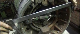
The correct clearance can be easily determined by using a feeler gauge, which should be inserted between the crosshead and the rocker seat with some force. To adjust the gap, loosen the locknut and adjust it. The optimal values are considered to be 0.254 mm at the intake valve, and 0.508 mm at the exhaust valve.
After setting the gap again, tighten the lock nut and be sure to use the feeler gauge again to make sure the gap is set correctly.
Having adjusted the valves with the numbers indicated above, rotate the crankshaft 360° and measure the gaps on the remaining valves. When all the valves are adjusted, you need to put the gasket and engine cover back. However, you may have to use a new gasket if the old one is cracked or deformed.
Mercedes Axor truck repair
The Mersremzone car service specializes in servicing the family of heavy trucks of the German Mercedes brand. We know that machines of this brand are characterized by high reliability and endurance, but even this equipment periodically breaks down and needs repair.
If your truck's brakes have failed, the starter needs to be replaced or the rear axle gearbox needs to be adjusted, then use the services of our center. With us you can undergo diagnostics and receive the necessary assistance provided by highly qualified auto mechanics. Most of them have more than 7 years of experience working with German trucks, which makes it easy to identify and fix the most complex faults.
Mersremzon service
Repair of Axor Mercedes trucks is carried out by specialists from our center using modern equipment and tools. The following services are available to clients who own equipment from a leading German manufacturer:
- Diagnostics. It is performed using a computer and allows you to accurately determine the problem, as well as find the best ways to troubleshoot problems.
- Maintenance of Mercedes Axor according to the manufacturer's regulations. During the process, oil, technical fluids and consumables are replaced.
- Restoration or replacement of worn and damaged spare parts, spark plugs with new ones or those received from disassembly. Moreover, such repairs are cheaper with us than with an official dealer. Since many parts come to our warehouse from truck dismantling. Moreover, their integrity and quality are carefully checked.
We repair and replace the compressor, rear axle, brake system, gearbox and engine of Mercedes Benz Axor model trucks and know all the features of this modification. Our employees have many years of experience and can easily determine why the truck won’t start, whether it needs repair of the internal combustion engine, power steering pump, clutch or other important component.
Cost of maintenance and repair of Mercedes Axor trucks
To ensure that your truck fleet is in excellent technical condition, use the services of Mersremzon service specialists. The convenient location of the workshops will allow you to quickly reach us from any part of Moscow. The extensive experience of our employees guarantees high-quality car repairs, from oil seal replacement to complete disassembly of the generator.
But a more significant advantage of working with us is the affordable prices for diagnostics, maintenance and repair of Mercedes trucks. Tariffs for all types of work performed can be found on the website in the table below.
Preparing the car
The machine being manipulated is placed on a flat surface. The driver's cabin reclines and locks. The upper part of the gas distribution mechanism is dismantled and the pump is turned off.
KamAZ 43118:
Devices:
- Keys: open-end for 13, ring for 14;
- Screwdrivers;
- Steel rod;
- Set of measuring plates.
Fixing the main chamber piston at the top
- Check the fixation force of the camera heads;
- Move the flywheel stop device down;
- Remove the flywheel housing protection plate;
- Insert the steel rod into the hole in the flywheel, turn clockwise until the product stops. Position – beginning of mixture injection (cylinder one).
Flywheel retainer, KamAZ engine:
Setting gaps
- Rotate the flywheel (2 holes – 60°, each 30°);
- Adjust the spacing of the first pair of cameras (1st and 5th). Using a 14 ring wrench, loosen the nuts
- adjusting screws. Use the 0.3 plate to adjust the intake valve, and the 0.4 plate to adjust the exhaust valve.
- Fix the nut, force 33-41 Nm.
- Adjust the spacing in chambers one through eight.
Installing the crankshaft for cylinder adjustment
Now we remove the stopper and rotate the crankshaft through two holes in the flywheel, which corresponds to a rotation angle of 60 degrees; in this position, the valves of cylinders 1 and 5 are completely closed.
Crankshaft rotation direction
You constantly get confused in the direction of rotation of the crankshaft. To test yourself there is a simple way, stand in front of the cabin, and imagine that you are starting the engine from the handle clockwise, in this direction the flywheel should rotate, that is, if you rotate the flywheel from below using a rod, the rod will move towards the batteries
1 . 5 — 4 . 2 — 6 . 3 — 7 . 8
So, we adjust the valves of cylinders 1 and 5. Then we rotate the flywheel through 6 holes, which corresponds to 180 degrees of rotation, and adjust the valves of cylinders 4 and 2. We turn 6 more holes and adjust the valves of cylinders 6 and 3. And for the last time we turn it by 6 holes and adjust the valves of cylinders 7 and 8.
Setting the TDC of the first cylinder at the moment of compression
It is advisable to carry out the adjustment together with a partner, since it is necessary to rotate the crankshaft from below the car and it is advisable to use an inspection hole. There is a special window in the flywheel housing, and holes on the flywheel itself. If a rod of the appropriate diameter is inserted into these holes through the viewing window, then with its help the flywheel can easily rotate the length of the technological window, when the rod rests on one side of the window, another hole will appear on the other, and by moving the rod into it we can continue rotating the flywheel. The flywheel must be rotated in the direction of rotation of the crankshaft, as it rotates when the engine is running. There is a stopper on the top of the flywheel housing. And there is a recess on the flywheel; when the stopper enters this recess, the flywheel will take a position corresponding to the position of the piston of the first cylinder at TDC.
But we need to bring the piston to TDC at the moment of fuel compression in the first cylinder. Therefore, we focus on the mark located on the high-pressure fuel pump (HPF). As soon as the mark on the fuel injection pump is set at the time of fuel injection in the first cylinder, only then does the locked flywheel assume the correct position.
Main stages of work execution
Do-it-yourself adjustment of KAMAZ 740 valves implies strict adherence to the stages of all work. The main steps to follow when adjusting the valves:
- You will need to carefully remove the cover that covers the cylinder heads. You should check whether all the bolts are tightened; if not, then tighten them to the optimal tension.
- You will need to correctly install the clamp to the lowest possible position.
- After this, you will need to remove the hatch cover, which is installed at the bottom of the clutch housing. By turning the crankshaft with little physical effort and smooth movements, you will need to bring it to a position where the installed retainer, under the influence of a spring, engages with the flywheel. For motors of certain models 7303.10, as well as 740.14 and engine type 740.11, the special marks that are located at the end of the injection pump mechanism and the working clutch must completely coincide. It is recommended to take this moment as seriously as possible, because it is important for the correct performance of the specified work on the KAMAZ vehicle.
This arrangement of the crankshaft indicates the beginning of fuel supply in the first cylinder. In cases where such marks do not coincide, it will be necessary to remove the clamp from its engagement with the installed flywheel. To do this, you can turn the shaft 1 turn, then the lock should return to its original place. To rotate the crankshaft to the required position, it is recommended to use a crowbar. It will need to be rotated at an angle that is equal to the existing gap between a row of holes, which will fully correspond to an angle of 30 degrees. Then move the lock and turn it 90 degrees. After completing this moment, it will need to be installed in the highest possible position.
At this stage of work, you will need to check how tight the special nuts for the cylinder rocker arms are tightened. If KAMAZ Euro 2 valves are adjusted, then the torque must be within certain limits, which range from 41.2 to 52.6 N.m. To adjust you will need:
- In order to correctly adjust the valve clearances on a KAMAZ 740, you need to slightly loosen the lock nut of the special screw to make the adjustment, and also install a feeler gauge of optimal thickness.
- Then, by rotating the screw, set the gap to 0.30 millimeters for the intake valve and 0.40 millimeters for the exhaust valve.
- If adjustment of KAMAZ Euro 3 valves is required, then this procedure, as a rule, does not differ from that discussed above and can be performed in the same order.
It is necessary to adjust valves on KAMAZ when it is required due to poor engine performance. This point must be taken into account and understood when there is a noticeable loss of engine power during operation. Adjustment of valves on KAMAZ 5320 should be carried out using all the above recommendations.
Let's consider the optimal procedure for adjusting valves in KAMAZ 740, which will help significantly save time on performing this procedure. You need to rotate the installed crankshaft approximately 60 degrees from TDC and begin adjusting the valves in cylinders 1 and 5. After this, we rotate it 180 degrees and carry out the adjustment process for cylinders 4 and 2. Then, again by 180 degrees, we adjust the 3rd and 6th cylinders and the last ones we adjust are the 8th and 7th cylinders after turning by 180 degrees.
When the above stages of work are completed, you will need to start the engine of the KAMAZ vehicle and listen carefully to how it works
You will need to pay attention to extraneous knocks and noises that should not exist. When everything works stably and without unnecessary noise and knocking, you will need to install the previously removed covers, which are located on the cylinder block
WILL BE SHOWN ON THE SHOW
Nowadays, all heavy Kama trucks are equipped with 16-speed ZF gearboxes manufactured at the CF Kama joint venture. So the KamAZ-5490 is equipped with a 16-speed ZF-Ecosplit. The German Axor uses a Mercedes gearbox, but the ZF is no worse: DAFs, MANs and Renaults are equipped with units of the same design. The options include an “automatic” AS-Tronic: this is a 12-speed automated gearbox.
The next successful solution is the use of a Mercedes drive axle, which is known from the Aksor and Aktros. It has a hypoid gearbox with a gear ratio of 3.077. There is a differential lock.
The front suspension beam from the KamAZ-6520 family can withstand a load of 7100 kg. There are conical kingpins of increased diameter and length, bronze bushings, and in the hubs there are internal bearings of larger diameter. All brake mechanisms are disc, and with such previously rare safety systems as ESP and ASR. This is the second vehicle in the history of KamAZ with disc brakes; The championship remained with its smaller brother - the medium-duty model 4308.
The drive axle is mounted on air suspension, but if the restyled KamAZ-5460 tractor used a four-cylinder design, here it is a two-cylinder design, like on a Mercedes.
It’s okay that the cabin came from the Aksor, produced since 2001. Against the backdrop of the usual domestic scene, it seems like it’s from the future.
The frame is original. It is assembled from imported rolled steel using modern technology: all brackets and traverses are fastened with high-strength bolts. An underrun protection bar is mounted under the first cross member, and on the front left side member there is a massive integral bracket that combines the front spring brackets and the cab mount. They put power steering on it. Such integral brackets began to be used in Europe quite recently, but here they are already on the assembly line. The bracket reduced the movement and twisting of the side members in this area. As a result, the car's handling has improved.
The frame is technologically advanced: it can be used to build a long-wheelbase tractor for a road train with a trailer with a central axle arrangement. In Europe, the length of such couplings is 18.75 m, but in Russia “twenty” is allowed: with such dimensions, the volume of the cargo compartment will increase from the usual 86 (93) to 110 cubic meters. This means that the car will pay for itself faster.
PLUS A modern machine built on the best units from world manufacturers MINUS KAMAZ, although 20% cheaper than imported analogues, is still expensive for our carriers
Source: www.zr.ru
Procedure for adjusting KAMAZ valves with a Cummins engine: clearances
The procedure for adjusting KAMAZ valves and the procedure for adjusting KAMAZ valves with a 6-cylinder Cummins engine do not differ from each other.
Adjusting KAMAZ Euro-4 valves involves first removing the rocker cover from the engine. To do this, you need to disconnect the crankcase breather from this cover. First, remove the oil drain lines from the breather.
Then it is necessary to disconnect the fitting related to the breather tube from the back side of the cover of these rocker arms, then it is removed from the rear camshaft housing. To do this, it is necessary to loosen the clamp attached to the breather tube, then pull the fitting in a vertical direction. Then, to provide access to the valves, you need to remove the rocker cover with gasket.
KAMAZ Euro-1 valves are adjusted when the temperature of the cooling fluid does not exceed 60 degrees. Any KAMAZ valve adjustment scheme implies this.
After turning the crankshaft, you need to establish the dead top point of the piston of the 1st cylinder of the engine.
On an engine that does not have a system that recirculates used gases, the top dead center is set as follows: a sensor ring indicating the engine speed is placed so that the part without grooves is at 12 o’clock.
In the case when both rocker arms on the first cylinder are not released for adjustment, it is necessary to rotate the crankshaft, making a full revolution.
KAMAZ Euro-3 valve adjustment diagram
On an engine on which a used gas recirculation system is installed, the location of the dead top point of the 1st cylinder is a torsional vibration damper or a sensor ring indicating the engine speed.
It is necessary to install the ring or damper so that the mark is at 12 o'clock.
If it was not possible to release the rocker arms of the 1st cylinder, you still need to rotate the crankshaft 360 degrees. Then you can start measuring the valve and rocker clearances.
This is exactly the sequence of adjusting KAMAZ valves.
Operating principle of valves
A diesel engine has two valves per cylinder:
- inlet valve (admits the combustible mixture);
- exhaust valve (releases the combustible mixture).
After the engine warms up, the process of expansion of some of its parts begins. Then it turns out that in a cooled state there must be gaps of a certain size between the engine parts.
If the valve adjustment was performed incorrectly, the efficiency of the Mercedes Actros engine may sharply decrease. At the same time, the service life of its parts will also be reduced. If the gaps between the parts are too small, the valves will burn out, and if they are too large, the valves will not open to their full potential. As a result, the motor power will decrease and periodic metallic tapping can be heard.
Mercedes Actros valve adjustment algorithm
Every time the car travels 30,000 km, the valves must be adjusted. They are individual for each brand of truck.
The procedure for adjusting the valves occurs according to the following scheme:
The nut in the pusher is released. The head of the adjusting bolt and the face of the pusher body are grasped using two wrenches. The key holds the pusher nut, and the bolt head rotates in different directions. This procedure is carried out in order to obtain the required clearance.
The gap is determined using a feeler gauge. When setting the gap, the bolt head is fixed. The bolt head should be secured with extreme care and caution so as not to disrupt the clearance.
ATTENTION!
Danger of incorrect valve clearance!
- The brake piston with exhaust valve must be installed so that it can be completely pressed into the valve rod.
- Loosen the locknut (2) and unscrew it a few turns.
- When tightening the adjusting screw (1), press the valve rod (3) down several times until it stops.
- The engine oil must completely drain from the brake piston (4) with the exhaust valve.
When to adjust valves: main signs of a problem
Valve adjustment, as mentioned above, must be carried out after every 30,000 km. If the diagnosis was not carried out on time, or the valve adjustment was not performed by a professional, then the following problems may appear:
- Decrease in car engine power.
- The appearance of extraneous sounds: knocking, unnecessary and unusual sounds in the engine compartment.
- The carburetor begins to malfunction.
- Difficulties in performing functions arise in the mechanisms and components of the car.
Features of valve adjustment of the Cummins 6ISBe engine
Unbalancing valve clearances is a normal phenomenon that occurs even if all operating rules are followed. Valve adjustments must be made every 150-200 thousand km.
How to determine that you urgently need to adjust the valves of a Cummins 6ISBe 285 engine? A metallic sound occurs when the engine is running, and fuel consumption also increases when engine power decreases. Before starting work, you must wait until the engine and coolant cool down to at least 60°C.
Six-cylinder Cummins 6ISBe engines come in two power options - 285 and 300 - valve adjustment for both modifications is the same.
It is necessary to gain access to the crankshaft, so the first step in the work will be to disconnect the rocker cover: you need to remove the breather tube fitting from the cover and rear camshaft housing, after which the cover can be removed.
The crankshaft must be turned so that the first cylinder is installed at top dead center: the speed sensor must point straight up with the part without grooves.
Now it is necessary to measure the rocker arm clearances, which should be 0.25 mm at the inlet and 0.5 mm at the outlet. Adjustment is made by loosening the locknut and setting the required parameters with a special adjusting screw. You can check the correctness of the adjustment with a feeler gauge, which should not go in and out too freely, but should not get stuck.
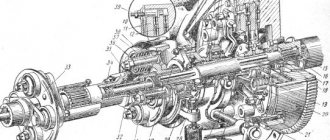
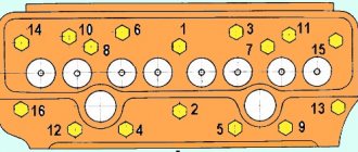
The operating order of Kamaz cylinders
/ Operating order of Kamaz cylinders
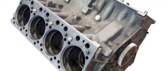
The main feature of the Kamaz 740 engine structure is the asymmetrical arrangement of the left row of pistons relative to the right one in such a way that the left piston group is extended 29.5 mm further. The fact is that there are two opposing connecting rods installed on the crankshaft journal, which determines the unique operating order of the Kamaz cylinders. The explosion sequence of the fuel mixture is the sequence 1→5→4→2→6→3→7→8.
Thanks to a shortened crankshaft with 8 pistons and 4 journals, the compression in the cylinders increased significantly, which in turn led to an increase in engine efficiency and power. The power in Kamaz 740 engines also increases due to the clearly tuned operation of the timing belt, including the valves.
What is the operating order of the Kamaz 740 cylinders?
According to the technical regulations of EU countries, the first cylinder in the Kamaz 740 engine is considered to be the one located in the right row at the front of the vehicle. This is usually called the master cylinder. The injectors have the same numbers as the cylinders on which they are installed. Therefore, the main injector corresponds to the master cylinder. Cylinder numbering starts from the right row, in which cylinders 1-4 are located. In the left row, cylinders 5-8 are respectively located. For both the right and left rows, the numbering starts from the front of the car.
| Knowledge of the operating order of Kamaz cylinders will be useful when debugging fuel injection after replacing the fuel pump, as well as when adjusting the timing belt, since the valves must open with a certain frequency and duration. Only in this case does smooth operation of the motor become possible. The special design of the Kamaz 740 engine makes it significantly smaller than Russian engines and more reliable than foreign ones. Kamaz 740 is ideal for working in the harsh conditions of the continental climate of our country, since it is quite easy to start in the cold season. |
spb.camsparts.ru
How to adjust valves on KAMAZ
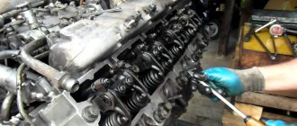
The work must be carried out on a cold engine (the time period after stopping it should be at least 30 minutes). At the same time, you can remove the valve covers immediately after stopping, which will speed up the cooling process of the rods and rocker arms (adjustments cannot be made on a hot engine due to the natural thermal expansion of its elements, as well as the risk of burns).
Before adjusting the valves on a KAMAZ, enlist the help of a partner, and to ensure safety, additionally perform the following steps:
- apply the handbrake;
- install anti-rollbacks;
- Turn off the fuel supply to the engine by pulling the engine stop handle all the way.
The work itself is carried out as follows:
Check the tightening torque of the installed cylinder head mounting bolts, which should be 157-176 N/m (if necessary, they need to be further tightened). Install the motor flywheel lock in the lower extreme position. Remove the hatch cover from the lower half of the car's clutch housing and insert a small crowbar into the hole in the flywheel. Now slowly turn your crankshaft until the retainer engages with it. This position will correspond to the moment when diesel fuel injection begins on the 1st working cylinder of the engine (for control at this moment, the high pressure pump drive mark will be in the upper extreme position). Check the position of the marks located on the end of the injection advance coupling for a portion of diesel fuel and the flange located on the drive half of the injection pump coupling. If the risks are at the bottom, then you need to remove the lock that is engaged with the flywheel and rotate the crankshaft 360 degrees until it engages again. Set the motor flywheel lock to the uppermost position. Now turn the crankshaft at an angle of 60 degrees in a counterclockwise direction (looking at it from the flywheel side). In this case, the distance between adjacent holes will be 30 degrees, which corresponds to the position when the valves of the 1st and 5th cylinders are in the closed position (at the same time, the valve hoses should be easily rotated without the use of any tools). Check the tightening torque of the nuts securing the rocker arms (it should be 42-54 N/m) and, if necessary, adjust them with a torque wrench. Now check the actual gaps between the end surfaces of the valve stems of these cylinders and the rocker arms. The size should be 0.3 millimeters for the intake valve (right bank of cylinders) and 0.4 millimeters for the exhaust valve (left bank). To adjust the clearances, loosen or tighten the adjusting screw until the feeler gauge between the rod and the rocker moves with minimal force without bending. After achieving the desired result, hold the adjusting screw with a screwdriver and tighten the lock nut without removing the dipstick. You can also use a 0.35 mm probe for the intake and 0.45 mm for the exhaust for control. It should not fit into the existing gap. At the same time, it is advisable to check the condition of the rod, which should rotate without difficulty or jamming
The latter indicate the presence of curvature, which requires replacement or repair. After adjusting the valves of the first cylinder, go to the fifth and repeat the previous step again. Now turn the crankshaft half a full turn and adjust cylinders No. 4 and No. 2 by analogy with step 8. Turn the crankshaft 180 degrees again and adjust cylinders No. 6 and No. 3 by analogy with step 8. Rotate the crankshaft again 180 degrees and adjust cylinders No. 7 and No. 8 by analogy with point 8. Now you can test run the engine and pay attention to its operation.
If you have the appropriate tools and skills, the adjustment can be done independently both on KAMAZ and on other vehicles. Otherwise, we recommend that you seek help from a service station. This will save time and prevent errors that can have a detrimental effect on the condition of the entire engine, and in some cases require a major overhaul of the latter. If you have any questions, please contact our service, where honesty towards the client, affordable price, high quality of services and prompt completion of work are guaranteed.
Typical situations leading to car malfunctions and breakdowns
Mercedes trucks are considered very reliable and have one of the most reliable engines, the service life of which is calculated to be up to 1 million km.
mileage This is exactly how far you can drive, subject to professional service and timely technical inspections. Like any other vehicle, these trucks require careful handling and timely maintenance. Most malfunctions are associated with careless handling of the car and untimely maintenance. If the driver overloaded the truck, then you should not wait and hope that the vehicle will work for the entire service life for which it was designed.
During a routine inspection, the Actros engine requires good (original) oil - synthetic or semi-synthetic.
There are also some problems - there is no oil level sensor in the box, and if the oil drain pipes fray, the oil will leak out completely very quickly while driving and is not noticeable to the driver. There are also problems with the brake system - jamming of the caliper, failure of the valves. But all these problems are associated with only one thing - careless maintenance.
Some car owners do not believe that the ABS sensor can fail; for this purpose, we specially took a photo of that same ABS sensor, so that you can see how thin the core winding of this sensor is. Most often they wear out due to vibrations and overheating.
Fuel system malfunction
A common malfunction of the fuel system is low-quality fuel, so we advise you to refuel only at proven gas stations to avoid problems. The photographs show what the use of low-quality fuel on the 1st coarse filter leads to:
Similar problems may arise with the 2nd fine filter:
Failure of the MR engine control unit (PLD)
The cause of the breakdown of the MR engine control unit (PLD) in this case is the connecting rod resting against the control unit. As a result, this block cannot be restored:
Clutch disc malfunction and consequences
As a result of driving for a long time on a damaged clutch disc, this led to the failure of the flywheel. This malfunction, which resulted in vehicle downtime, could have been avoided by contacting the technical center in time to promptly replace the clutch disc.
Damage to the cylinder head
Untimely and poor quality adjustment of the engine head valves can lead to more serious consequences, such as a broken cylinder head, burst valves, broken seat and piston damage.
Broken valve rod pusher.
Also, if the valves are adjusted incorrectly or untimely, the valve rod pusher begins to “dangle” between the valves and the camshaft, as a result of which this damage occurs. This breakdown can be avoided in time by contacting our specialists, who will perform valve adjustments efficiently and professionally.
Extraneous noise in the gearbox
Prevent serious transmission damage in a timely manner by possibly checking the transmission drain plug, which has a magnetized surface to attract metal shavings. By the appearance of the plug shown in the photograph, we can say that the gearbox requires serious repairs.
Wiring damage or fire
Damage to the wiring, short circuit, or in the worst case, fire, is a consequence of improper operation of the car. This can be avoided by simply washing the car, since exposure to an aggressive environment (reagents in winter, rain, dirt stuck to the wiring), oil, destroys the insulation of the wiring, making it rough and brittle.
Negligent attitude towards cars
And finally, an exceptional case is a non-working window regulator. After numerous checks, the cause was an ordinary table fork, which, for reasons unknown to us, got inside the door.
All of the listed malfunctions and breakdowns are a consequence of improper operation of the vehicles. It is possible to avoid all this with timely technical inspection of the car, changing the oil and pads, which you can do with us.
Proper operation and care of your car will extend its service life and reduce your maintenance costs.
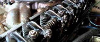
Adjustment of valves
The adjustment of KAMAZ valves itself does not cause much difficulty; it is necessary to establish the permissible gap between the valve stem and the rocker arm; this is done using an adjusting screw locked with a nut. Unscrew the lock nut, loosening the adjusting screw, and install the feeler gauge between the rocker arm and the valve. On the intake valves it has a size of 0.35, on the exhaust valves 0.45 mm. We tighten the adjusting screw so that the feeler gauge is not tightened and moves between the rocker arm and the valve stem, and at the same time this movement should not be free. Then tighten the lock nut while holding the adjusting screw with a screwdriver. After adjustment, install the valve covers.
When you start the engine, you will immediately feel that it has become more responsive, as the cylinders begin to work more evenly in relation to each other.
Source
Setting the gap
Experts begin adjusting valves by setting the distance between the valve and the rocker arm. To do this, use a screw and a lock nut - a lock. It is then unscrewed to install the dipstick. This is a fixed length: 0.35 mm for the intake valves and 0.45 mm for the exhaust valves.
Then the adjusting screw is tightened, but check that the feeler gauge is not fixed and remains mobile. The next step is tightening the nut while holding the screw with a screwdriver. Once the clearances are set, the valve covers are installed.
The final stage is checking the accuracy. To do this, the engine starts and, if it runs smoothly and the extraneous rattling has disappeared, you can operate the car. The procedure is repeated when no significant changes occur. The adjustment of valves 65115.6520 (Euro4) KAMAZ must be completed to the end; one cannot be content with a mediocre result. It's a waste of time and effort.
“Technical Assistance 24 Volt” solves technical problems of varying complexity, including setting gaps on site. To use our services, you need to make a phone call, tell us where to come and describe the problem.
What is injection timing and why does it need to be adjusted?
The moment of injection is the first seconds of fuel supply, on which the operation of the entire engine depends. The supply is carried out using a piston, which moves to the upper position, but the valves remain closed at this moment. The movement of the piston compresses the air, which starts the flow of fuel.
Engine starting and the stability of its operation depend on the speed and force of the jet, so for each machine it is necessary to adjust the injection. Of course, a logical question arises as to why it is not possible to set all the settings automatically and fix the position of the piston in the Kamaz 740 cylinder head. However, in reality everything is much more complicated. Firstly, the engine of special equipment can be modernized and changed depending on the year of manufacture and model, and the second reason is the difference between winter and summer fuel. Such conventions prevent the use of the same settings over a long period, and to maintain the functionality of the equipment, adjustments are made manually.
As a reference setting, manufacturers of special equipment set marks at which the injection is set at the moment the machine is released from the assembly line. But you should not count on the fact that the factory settings do not require intervention and you can safely use these tags during operation. These settings are calculated subject to the use of a certain oil and GOST fuel, which is rarely used in practice. Typically, the oil used is not the one specified in the regulations, but diesel fuel, which is currently on sale, can be used as fuel.