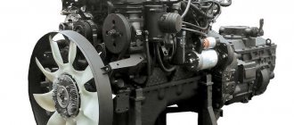
Features of the fuel injection pump device MTZ-80, 82. Detailed diagrams and useful recommendations.
Consisting of two fuel tanks, two filters (coarse and fine), and a high-pressure fuel pump (HPF), the fuel system of this brand of tractor is quite simple and standard for most both diesel and gasoline engines. Looking at the MTZ-80 fuel injection pump in the diagram below and knowing the detailed device with all its component parts, you can have little doubt about the possibility of independently repairing this equipment. The fuel pump of the MTZ tractor - 80, 82 and its later modifications has a total of more than 70 parts.
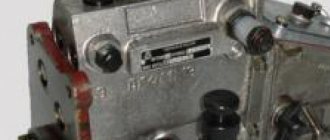
Injection pump device for MTZ - 80, 82
UTN-5, as the fuel pump for the Belarusian brand of tractors is called, is made of durable aluminum alloy and is available in two possible installation options - left and right, depending on the design features of the flange mounting. Throughout the entire body, it is divided into two cavity parts by a special partition, where in the lower cavity there is a shaft with a pump drive, and in the upper cavity there are separate sections of this pump.
You can read the full detailed structure of the high pressure fuel pump of the D-240 engine below
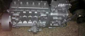
Fuel pump with regulator:
1 - pressure fitting; 2 - clamps; 3 - spring; 4 - discharge valve; 5 — valve seat; 6 - gasket; 7 — plunger bushing; 8 - plunger; 9 - plug; 10 — ring gear; 11 — rotary sleeve; 12 — regulator cover; 13 — rack rod; 14 — spring lever; 15 — regulator spring; 16 — enrichment spring; 17 — main lever; 18 — corrector housing; 19 — corrector rod; 20 — adjusting screw; 21 - intermediate lever; 22 — nominal bolt; 23 - bolt; 24 — regulator body; 25 — load axis; 26 - heel; 27 - coupling; 28 — heel axis; 29 — lever axis; 30 — regulator weights; 31 — thrust ball bearings; 32 — drain plug; 33 — cargo hub; 34 — shock absorber block; 35 — washer; 36 — bearing cup; 37 — oil deflector; 38 — control lever; 39 - cam shaft; 40 - plug; 41 — eccentric drive of the booster pump; 42 — flange for mounting the booster pump; 43 — adjusting washer; 44 — mounting plate; 45 — pump housing; 46 — oil supply hole; 47 — roller nut; 48 — splined bushing; 49 — mounting flange; 50 — pusher with roller; 51 — pusher adjusting bolt; 52 — spring plate (lower); 53 — plunger spring; 54 — spring plate; 55 — rack; 56 — bolt for bleeding; 57 — channel for fuel removal; 58 — bypass tube; 59 — bypass valve body; 60 - plug; 61 — valve ball; 62 — hole for fuel supply; 63 — channel for fuel supply; 64 - cut-off hole; 65 — inlet hole of the plunger sleeve; 66 - pin; 67 — hatch cover; 68 — adjusting screw; 69 — gasket; 70 - filler plug; 71 — adjusting screw; 72 — corrector spring; 73 - tightening screw.
Here you can see the entire fuel system of the Belarusian tractor:
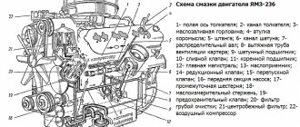
Diesel power system (diagram):
1 — muffler; 2 — air cleaner; 3 — coarse air filter; 4 — intake manifold; 5 — electric torch heater; 6 — fuel tank of the electric torch heater; 7 - drainage tube; 8 — high pressure tube; 9 — filler neck; 10 — fuel tanks; 11 - drain valve; 12 — fuel pipe; 13 — fuel coarse filter; 14 — fine fuel filter; 15 — tube from the fine filter to the fuel pump; 16 — tube from the sediment filter to the fuel pump; 17 — fuel pump regulator; 18 — fuel pipe from the booster pump to the fine filter; 19 — booster pump; 20 — bypass tube; 21 - fuel pump; 22 — nozzle; 23 — exhaust manifold; 24 - lower filter element; 25 - middle filter element; 26 - upper filter element.
At the upper cavity point of the UTN - 5 D-240 engines there are two longitudinal channels that form a square, one end of which is connected to the fine fuel filter, and the other, respectively, to the pump itself in the pump, where a bypass valve is mounted in the fitting.
Characteristics of fuel injection pump
The MTZ fuel pump belongs to the category of four-plunger units and is designed to ensure the necessary fuel circulation. In the design of the tractor, it is located in one block with a pumping analogue and a centrifugal regulator. The block is located on the left side of the D-240 engine, secured with bolts to the distribution cover.
Before you figure out how to add fuel to the MTZ injection pump, you need to become more familiar with its characteristics and features. Correct operation of the unit is ensured by the action of the crankshaft, which drives it through a gear mechanism.
Among the most significant characteristics of this important element it is advisable to include:
- manufacturer - Noginsk;
- spare parts catalog number - 4UTNI-1111005-20;
- scope of application - power units of the D series (from 240 to 248.1 modification) for various MTZ models;
- drive type - splined bushing.
The MTZ 82 fuel equipment is not a completely unique development, since it has foreign analogues. An example is the Czech-made PP4M9P1g-4201, which is almost identical in its technical design and characteristics.
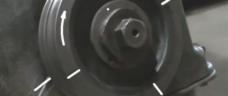
Operating principle of UTN - 5
A booster pump, a mounting plate with a flange and a regulator are attached to the outside of the fuel pump housing, and a high-pressure fuel line is connected to each of the fittings, through which the necessary fuel is supplied to the injector. The pump is driven by a crankshaft gear, which is connected to the intermediate gear and the gear of the pump itself.
If the pump has ever been repaired, then after each disassembly/assembly it is necessary to accurately check the angle of the gear connections, because if the angle is incorrect, malfunction is inevitable. The degree of inclination angle should always correspond to 22°30″ and, of course, preferably be checked by mechanics, and not independently.
Device
When planning to repair the MTZ fuel injection pump, you should familiarize yourself in more detail with the design of such an element. It is distinguished by a minimum number of elements and high reliability, which makes it possible to significantly simplify the procedure for adjusting the pump, as well as troubleshooting. The main components of this unit are:
- plunger pairs;
- frame;
- pressure type valve;
- pushers;
- camshaft;
- plunger drive mechanism.
Checking (adjusting) the fuel pump
Before checking, it is necessary to ensure that the locking cone of the discharge valve is tight and that there is sufficient pressure in the pump section located in the upper cavity.
Rotating the crankshaft, you need to move the regulator until the needle on the pressure gauge stops at 15 MPa. The engine is then stopped and the fuel supply is turned off using the control lever. When the pressure drops on the pressure gauge in less than 10 seconds, the valve is in good working order and can be used for further use.
To adjust the exact angle at which fuel begins to flow, you will need to screw in/unscrew a special adjusting bolt. When unscrewing the bolt, the angle will increase, and when screwing it back in, it will decrease accordingly. Please note that one turn (turn) of screwing in/unwinding adjusts the engine speed by approximately 30-50 revolutions. When the bolt is loosened, the performance and throughput of the pump decreases proportionally, and when tightened, on the contrary, it increases.
Theoretical recommendations
You can logically calculate that as the fuel supply to the engine increases, its torque also increases, which naturally increases the rated power of the D-240 engine. In addition, the speed of operation is increased to the limits of its capabilities.
Changing the oil in the UTN-5 pump is necessary only after disassembly and repair, and is not necessary for everyday use of the tractor. Filling of diesel oil should be done through the injection pump crankcase in a volume of 150-200 ml.
Read more: MTZ tractors all models
Pump faults
The cause of wear of parts and subsequent failure of the unit is a violation of the tightness of the seals. Destruction of seals occurs as a result of temperature, mechanical loads during rotation, as well as friction when solid oxide particles and scale enter the engine water jacket.
If a minor pump leak is detected, it is recommended to carry out an inspection and replace the seals of the unit. Ignoring it leads to unacceptable wear of parts, which subsequently increases the repair budget. An unfortunate result of untimely maintenance is the discovery, during disassembly of the pump, of mechanical chips and gouges in the cast iron casing in the seal contact areas. Often, replacing seals in a damaged housing does not have a positive effect and the pump continues to leak. In the end, you have to purchase and install a new unit.
Pump repair and maintenance
Before purchasing a repair kit for pump inspection, pay attention to the design of the seal and the size of the shaft rotation bearings, since the dimensions of the parts differ depending on the year of manufacture of the pump.
Dismantling the unit
The inconvenience of the process of dismantling the pump lies in the narrow distance between the block and the radiator of the MTZ 80 tractor. The success of quick disconnection depends on the availability of an arsenal of socket wrenches and wrenches for them that correspond to the design features of the location of the unit, as well as the professionalism of the mechanic.
To disconnect a node from a block, perform operations in the following sequence:
- Raise the tractor hood
- Loosen the tension and mounting bracket of the generator
- Remove the drive belt
- Unscrew the radiator diffuser
- Disconnect the pipes from the pump
- Loosen the three bolts securing the pump to the block and remove the assembly.
Disassembling the pump
The presence of bench saws for fixing and a screw puller for pressing off the pulley hub and shaft with bearings will ensure quick and comfortable disassembly of the unit.
The pump is disassembled in the following order:
- Loosen the fastening bolt and remove the impeller with seals from the shaft
- Unscrew the fastening bolts on the hub of the drive pulley, disconnecting the fan
- The central nut securing the pulley to the shaft is unscrewed
- Having fixed the pump body in the cleats, using a screw puller or by gently striking the circumference of the inner rim of the pulley, remove the part from the shaft key connection
- Dismantle the retaining ring securing the shaft with bearings in the housing bore
- Press out the shaft with bearings using a screw puller or by carefully striking the end of the shaft from the impeller side, having first screwed the fastening bolt into the shaft so as not to spill the end of the part with the internal thread.
After disassembly, clean the housing and impeller from dirt and scale. Particular attention is paid to the contact surfaces of seals and gaskets. Using sandpaper, scale deposits and small shells on the contact surfaces with seals are cleaned, especially in the pump housing around the shaft hole.
If large potholes or cavities are identified that cannot be cleaned, the unit body must be replaced. A shaft with unacceptable wear in the bearings, bearings with axial play in the cages are also replaced. To achieve a positive result when eliminating pump leaks, reusing seals and seals is unacceptable.
Assembly and installation
The assembly process is carried out in reverse order. All pump parts must take their places. The result of correct assembly is free rotation of the impeller by hand without distortions or snags on the body, without axial play in the shaft and impeller seats. The crucial point in assembling the unit is the landing of the pulley hub on the shaft key. When pressing the part onto the shaft, it is important not to displace the key from the landing groove and ensure a reliable connection without radial and axial play. Connection is carried out with the contact surfaces of the block and pump thoroughly cleaned through a new gasket.
For a comfortable future inspection of the unit, experienced tractor drivers install a similar part made of brass instead of the standard impeller fastening bolt, thus preventing the formation of corrosion, which makes disassembly difficult.
Service
Pump maintenance operations include monitoring the drive belt tension and timely lubrication of the unit bearings. Regular lubrication is carried out by injection through a grease fitting during maintenance 1. The belt tension is changed by the position of the generator when the mounting bracket is rotated.
The correct tension ensures the belt moves with minimal slippage and is controlled by the deflection of the middle of the large drive branch “alternator pulley - crankshaft pulley” when pressed with a force of 30...50 N by 10...15 mm. Control is carried out every 60 hours of operation. When putting a new engine into operation, the tension is checked no later than after 2 to 3 work shifts. Excessive tension increases the load on the drive unit support bearings and accelerates their wear.
Source