The article describes how to build a three-phase (single-phase) 220/380 V generator based on an AC asynchronous electric motor. A three-phase asynchronous electric motor, invented at the end of the 19th century by the Russian electrical engineer M.O. Dolivo-Dobrovolsky, has now become predominantly widespread in industry, agriculture, and also in everyday life.
Asynchronous electric motors are the simplest and most reliable to operate. Therefore, in all cases where this is permissible under the conditions of the electric drive and there is no need for reactive power compensation, asynchronous AC motors should be used.
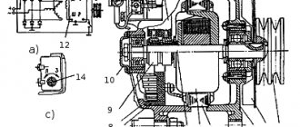
There are two main types of asynchronous motors: with a squirrel cage rotor and with a wound rotor. An asynchronous squirrel-cage electric motor consists of a stationary part - the stator and a moving part - the rotor, rotating in bearings mounted in two motor shields. The stator and rotor cores are made of separate electrical steel sheets insulated from one another. A winding made of insulated wire is placed in the grooves of the stator core. A rod winding is placed into the grooves of the rotor core or molten aluminum is poured. Jumper rings short-circuit the rotor winding at the ends (hence the name short-circuited). Unlike a squirrel-cage rotor, a winding made like a stator winding is placed in the slots of a phase-wound rotor. The ends of the winding are brought to slip rings mounted on the shaft. Brushes slide along the rings, connecting the winding to a starting or control rheostat.
Asynchronous electric motors with a wound rotor are more expensive devices, require qualified maintenance, are less reliable, and therefore are used only in those industries where they cannot be done without them. For this reason, they are not very common, and we will not consider them further.
A current flows through the stator winding connected to a three-phase circuit, creating a rotating magnetic field. The magnetic field lines of the rotating stator field cross the rotor winding bars and induce an electromotive force (EMF) in them. Under the influence of this EMF, current flows in the short-circuited rotor rods. Magnetic fluxes arise around the rods, creating a general magnetic field of the rotor, which, interacting with the rotating magnetic field of the stator, creates a force that forces the rotor to rotate in the direction of rotation of the stator magnetic field.
The rotor rotation frequency is slightly less than the rotation frequency of the magnetic field created by the stator winding. This indicator is characterized by slip S and is for most engines in the range from 2 to 10%.
, three-phase asynchronous electric motors are most often used , which are produced in the form of unified series. These include the single 4A series with a rated power range from 0.06 to 400 kW, the machines of which are highly reliable, have good performance and meet world standards.
Autonomous asynchronous generators are three-phase machines that convert the mechanical energy of the prime mover into alternating current electrical energy. Their undoubted advantage over other types of generators is the absence of a commutator-brush mechanism and, as a consequence, greater durability and reliability.
Blitz tips
The device is very dangerous, so it is not recommended to use a voltage of 380 V, unless absolutely necessary.
In accordance with precautionary measures and safety precautions, it is necessary to additionally install grounding.
Monitor the thermal conditions of development. It is not inherent to it to work at idle speed
To reduce the thermal impact, you should select the capacitor well.
Correctly calculate the power of the electrical voltage produced. For example, when in a three-phase generator only one phase is functioning, it means that the power is 1/3 of the total, and if two phases are working, respectively, 2/3.
It is possible to indirectly control the frequency of intermittent current. When the device is idling, the output voltage begins to increase and exceeds industrial values (220/380V) by 4-6%. It's best to isolate development.
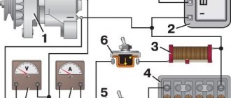
You should equip your homemade invention with a tachometer and voltmeter to record its operation.
It is advisable to provide special buttons to turn the mechanism on and off.
The efficiency level will decrease by 30-50%, this phenomenon is inevitable.
Step by step guide
- Since you will need to reconfigure the generator so that the rotation speed exceeds the engine speed , you must first connect the engine to the mains and start it. Then use a tachometer to determine the speed of its rotation.
- Having found out the speed, you should add another 10% to the resulting designation. For example, the technical indicator of the motor is 1000 rpm, then the generator should have about 1100 rpm (1000*0.1%=100, 1000+100=1100 rpm).
- You should select a capacitance for the capacitors. To determine the sizes, use the table data.
Possibility of control
Another feature of a synchronous generator (as well as an asynchronous one) is that the frequency and amplitude of the EMF induced at the stator terminals significantly depends on the rotor rotation speed.
Important! As the active load connected to the generator changes, the frequency of rotation of the generator shaft also changes in proportion to it, which leads to a change in the characteristics of the EMF created in the stator. This drawback forces the installation of an electronic voltage and frequency regulator in synchronous and asynchronous devices, which ensures that these parameters are maintained at the proper level (the regulator diagram is given below)
This drawback forces the installation of an electronic voltage and frequency regulator in synchronous and asynchronous devices, which ensures that these parameters are maintained at the proper level (the regulator diagram is given below).
AG voltage regulator circuit
Since the asynchronous generator operates on the principle of mismatched rotation of the fields of the moving and stationary parts, it is not possible to regulate the output parameters within the system. This is explained by the impossibility of organizing instantaneous voltage feedback by supplying part of the output signal from the stator to the rotor (only external voltage stabilizers can be used in AG).
This is another difference between asynchronous units and their synchronous counterparts, which in all other characteristics are very similar to the former.
Design features
Making an asynchronous generator with your own hands provides many advantages. It is a free source of electricity that can be used for various purposes. Moreover, even a novice master can do such work.
Structurally, the electric generator circuit will consist of several key elements:
- Rotor. It has blades, a turbine and a tail, which allows the structure to be mounted against the direction of the wind.
- Mast. It may be with or without stretch marks, which are needed to install the rotor. As a rule, the height of the masts is about 5-6 meters, although this depends on the winds in a particular region.
- Batteries. You can take old lead units.
- AC power generator. To do this, you need to prepare the engine for subsequent rework.
- A device with a display to regulate the battery charge level.
- Electricity converter. A power of 1 thousand watts is enough.
- Grounding system.
Reversibility effect
It is known that the operating principle of any device generating electric current is based on the conversion of one form of energy (heat, for example) into the form necessary to power the equipment. You can use so-called alternative (also called renewable) sources of energy supply, but this method is associated with even greater material and production costs.
It is much easier and more economical to make a homemade current generator by taking advantage of the potential capabilities of an old asynchronous electric motor at the user’s disposal.
The basis for such production is the well-known principle in electrical engineering of the reversibility of the processes of interaction of electromagnetic fields, which is explained by the specifics of the electrical processes occurring in this case. If in an engine three-phase current energy is used to convert it into mechanical rotation of the shaft, then in a generator everything happens exactly the opposite. In these units, the forced rotation of the armature is transformed into an electric current flowing through the phase windings, the power of which is spent to serve the consumer (see the figure below).
Generator operating principle
Thus, before making a sample of a homemade electric generator from a used asynchronous motor, in the most general case, you need to do the following manipulations:
- The terminals to which three-phase (or single-phase - for collector product samples) voltage is supplied must be turned into the output contacts of the generator;
- The moving part of the generator from which this or that mechanism (a machine tool, for example) operated should be equipped with a drive from an external source of mechanical rotational impulse;
Additional Information. Any propulsion unit suitable for specific conditions, rotating under the influence of the energy of burning fuel (gasoline, gas or diesel fuel), can be used as such a source. If a private household has a windmill or a homemade water mill, solving the problem of the drive is significantly simplified.
Due to the high cost of gasoline in suburban conditions, the only acceptable option is to manufacture a small power plant powered by a diesel engine or gas.
In this case, the engine, running on relatively cheap fuel, is connected through a special drive coupling to the shaft of the structure being constructed, which, after minor modifications, turns into an alternating current generator.
Asynchronous motor design
Just a few elements can be highlighted:
- Stator with winding.
- Front and rear covers with installed bearings.
- Rotor with short-circuited turns.
- Contacts for connecting to the electrical network.
If you think about it, it may seem that it is very simple to convert the engine into a generator, a photo of which you can examine in detail. But if you look more carefully, it turns out that not everything is so simple, there are plenty of pitfalls.
The stator consists of many metal plates pressed tightly together. They are also varnished; in some designs, to give strength, all plates are welded to each other. A wire is wound on the stator, it fits tightly to the core and is insulated from it using cardboard inserts. Bearings are located in the covers; with their help, not only does the rotor rotate more easily, but also its centering.
Conversion
How to practically convert an asynchronous electric motor into a generator with your own hands?
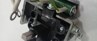
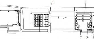
To connect the capacitors, you need to unscrew the top cover of the boron (box), where the contact group is located, switching the contacts of the stator windings and the power wires of the asynchronous motor are connected.
Open boron with contact group
The stator windings can be connected in a “Star” or “Triangle” configuration.
Connection circuits "Star" and "Triangle"
The nameplate or product data sheet shows possible connection diagrams and motor parameters for various connections. Indicated:
- maximum currents;
- supply voltage;
- power consumption;
- number of revolutions per minute;
- Efficiency and other parameters.
Engine parameters indicated on the nameplate
In a three-phase generator from an asynchronous electric motor, which is made by hand, the capacitors are connected in a similar “Triangle” or “Star” circuit.
The connection option with a “Star” ensures the starting process of generating current at lower speeds than when connecting the circuit in a “Triangle”. In this case, the voltage at the generator output will be slightly lower. Delta connection provides a slight increase in output voltage, but requires higher rpm when starting the generator. In a single-phase asynchronous electric motor, one phase-shifting capacitor is connected.
Connection diagram of capacitors on a generator in a “Triangle”
Capacitors of the KBG-MN model or other brands of at least 400 V non-polar are used; bipolar electrolytic models are not suitable in this case.
What does a poleless capacitor of the KBG-MN brand look like?
Since in everyday life it is almost impossible to calculate the required capacitor capacity for the engine used, a table was compiled experimentally.
Calculation of capacitor capacity for the motor used
| Generator rated output power, kW | Estimated capacity in, µF |
| 2 | 60 |
| 3,5 | 100 |
| 5 | 138 |
| 7 | 182 |
| 10 | 245 |
| 15 | 342 |
In synchronous generators, the generation process is excited on the armature windings from the current source. 90% of asynchronous motors have squirrel-cage rotors, without winding; excitation is created by a residual static charge in the rotor. It is enough to create an EMF at the initial stage of rotation, which induces current and recharges the capacitors through the stator windings. Further recharging already comes from the generated current; the generation process will be continuous as long as the rotor rotates.
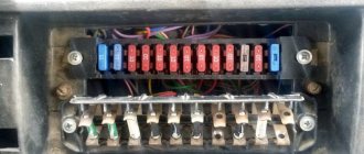
It is recommended to install the automatic load connection to the generator, sockets and capacitors in a separate closed panel. Lay the connecting wires from the boron generator to the switchboard in a separate insulated cable.
Even when the generator is not working, you must avoid touching the capacitor terminals of the socket contacts. The charge accumulated by the capacitor remains for a long time and can cause electric shock. Ground the housings of all units, motor, generator, control panel.
Do it yourself
To convert an electric motor into a functional generator, you will need to use non-polar capacitor banks, so it is better not to use electrolytic capacitors.
In a three-phase motor, you can connect a capacitor according to the following diagrams:
- “Star” - makes it possible to generate at a lower number of revolutions, but with a lower output voltage;
- “Triangle” - comes into operation at a large number of revolutions, and accordingly produces more voltage.
You can create your own device from a single-phase motor, but provided that it is equipped with a short-circuit rotor. To start the development, you should use a phase-shifting capacitor. A single-phase commutator-type motor is not suitable for conversion.
Appearance of the simplest wind generator using an asynchronous motor
Types of asynchronous machines
Different types of AG may differ in the following performance characteristics:
- The type of rotating part of the generating device - its rotor;
- The number of output or stator windings in the generator (the number of operating phases);
- The connection diagram of the three-phase generator coils - triangle or star, as well as the method of their placement and laying on the stator poles (photo below);
Placement of stator windings
The presence or absence of a separate field winding.
In accordance with the first of these characteristics, all known types of AG are equipped with a squirrel-cage or phase-wound rotor. The first of them is made in the form of a one-piece cylindrical structure, consisting of individual pins with two rings closing them (of the “squirrel wheel” type).
The phase rotor, unlike its squirrel-cage counterpart, has an inductive winding made of insulated wire, which ensures the creation of a dynamic electromagnetic field. Due to the peculiarities of its design, such a rotor has a high manufacturing cost and requires specialized maintenance.
The output windings of the stator, like the entire generator, can be single-phase or three-phase, which is determined by the direct purpose of this unit (when a voltage source of 220 or 380 Volts is required). Regarding the first of these designs, everything is quite clear, but the three-phase modification of the AG has one more feature regarding the electrical circuit for switching on the windings.
It is known that to form any three-phase power supply network in electrical engineering, two types of connection of windings are used, shifted in vector representation one relative to the other by 120 degrees. This:
Star switching, when the beginnings of the coils are connected at one point, where a zero wire is formed, and their ends diverge along three power lines (together with the neutral wire, there are four of them, as shown in the photo below);
4-wire star connection
A “triangle” connection, in which the end of one coil is connected to the beginning of the second, and so on until the chain is completely closed. The second connection option is used in 3-wire power supply lines, since there is no neutral wire in this circuit.
In each AG product, the connection according to one scheme or another is implemented in very specific ways, allowing the wires of all stator windings to be placed between the poles of its core. They are wound in such a way that each section of phase coils A, B and C is offset along the circumference from each other by exactly 120 degrees.
In conclusion of the review of generator devices, let us pay attention to the possibility of manufacturing an AG from an asynchronous motor. Such a prospect appears thanks to the well-known principle of reversibility of the action of electrical machines, according to which the direction of energy conversion can be chosen arbitrarily
Generator with neodymium magnets
How to make a generator from an asynchronous electric motor?
This homemade generator eliminates the use of capacitor units. The source of the magnetic field, which induces EMF and creates current in the stator winding, is built on permanent neodymium magnets. In order to do this yourself, you must sequentially perform the following steps:
- Remove the front and rear covers of the asynchronous motor.
- Remove the rotor from the stator.
What does the rotor of an asynchronous motor look like?
- The rotor is ground, the top layer 2 mm larger than the thickness of the magnets is removed. In everyday conditions, it is not always possible to bore a rotor with your own hands, in the absence of turning equipment and skills. You need to contact specialists in turning workshops.
- A template is prepared on a sheet of plain paper for placing round magnets, Ø 10-20 mm, up to 10 mm thick, with an attractive force of 5-9 kg per sq/cm, the size depends on the size of the rotor. The template is glued to the surface of the rotor, the magnets are placed in strips at an angle of 15 - 20 degrees relative to the rotor axis, 8 pieces per strip. The figure below shows that on some rotors there are dark-light stripes of displacement of the magnetic field lines relative to its axis.
Installing magnets on the rotor
- The rotor on magnets is calculated so that there are four groups of strips, in a group of 5 strips, the distance between the groups is 2Ø of the magnet. The gaps in the group are 0.5-1Ø of the magnet, this arrangement reduces the force of sticking of the rotor to the stator; it must be rotated with the efforts of two fingers;
- The magnetic rotor, made according to a calculated template, is filled with epoxy resin. After it dries a little, the cylindrical part of the rotor is covered with a layer of fiberglass and again impregnated with epoxy resin. This will prevent the magnets from flying out when the rotor rotates. The top layer on the magnets should not exceed the original diameter of the rotor, which was before the groove. Otherwise, the rotor will not fall into place or will rub against the stator winding when rotating.
- After drying, the rotor can be put back in place and the lids closed;
- To test an electric generator, it is necessary to turn the rotor with an electric drill, measuring the voltage at the output. The number of revolutions when the desired voltage is reached is measured by a tachometer.
- Knowing the required number of generator revolutions, the belt drive is calculated according to the method described above.
An interesting application option is when an electric generator based on an asynchronous electric motor is used in a self-feeding electric motor-generator circuit. When part of the power generated by the generator goes to the electric motor, which spins it. The rest of the energy is spent on the payload. By implementing the principle of self-feeding, it is practically possible to provide the house with autonomous power supply for a long time.
Benefits and Applications
The advantages of asynchronous generators include the following properties:
- AGs are resistant to overloads and short circuits, and also have a relatively simple design (this distinguishes them from more complex synchronous machines);
- The indicator of nonlinear distortion of a sinusoid does not exceed 2 percent (compare 15% for their synchronous analogues);
- Due to the low clear factor value, asynchronous devices guarantee high stability of the operation of the UPS and TV receivers connected to them;
- When powering welding equipment, they provide a significant improvement in welding quality;
- To stabilize the output voltage, they can use external automatic control devices;
- When rotating, AG rotors generate a limited amount of heat, which does not require powerful fan devices to compensate.
The latter property allows you to reliably seal the internal cavity of the unit, that is, protect it from the penetration of dust and dirt. Thanks to this circumstance, the scope of application of asynchronous machines capable of operating in conditions of great dust and high humidity is significantly expanding.
The possibility of sealing contributes to the fact that asynchronous type electric generators have a longer service life and can be operated at low temperatures. Let's add to this that it is allowed to connect loads of varying power to each of the phase windings of these units.
Additional Information. The permissible rate of unevenness of phase loads (the difference in the currents they consume) is about 70% for AG, which cannot be achieved when working with synchronous units.
A disadvantage that can be easily eliminated during operation is the rather “heavy” starting characteristics of the generator, which can be corrected by installing special starting amplifiers (figure below).
Starting generator circuit
These devices provide the ability to smoothly bring the generator into operating mode even with significant starting currents.
In all other respects, AGs have undeniable advantages over synchronous machines, some of the differences with which were discussed earlier. Due to these advantages, they are widely used as sources of electricity in the following economic areas:
- For power supply to equipment with rheostatic or regenerative braking mode (cranes, conveyors, etc.);
- In industrial equipment that does not require compensation for parasitic reactive power and does not have high requirements for the quality of supplied energy;
- In domestic and field conditions, where sources of cheap electricity with mechanical drive from a diesel engine are required;
- As a powerful charger that recharges batteries in car repair shops, for example.
In addition, they can be used as power sources to which welding units are connected, as well as to ensure uninterrupted power supply for critical healthcare facilities.
Assessing the level of efficiency - is it profitable?
The generation of electric current by an electric motor is quite real and feasible in practice, the main question is how profitable is it?
The comparison is made primarily with a synchronous version of a similar device , in which there is no electrical excitation circuit, but despite this fact, its structure and design are not simpler.
This is due to the presence of a capacitor bank, which is an extremely technically complex element that is absent in an asynchronous generator.
The main advantage of an asynchronous device is that the available capacitors do not require any maintenance , since all the energy is transferred from the magnetic field of the rotor and the current that is generated during the operation of the generator.
The electric current created during operation virtually does not have higher harmonics, which is another significant advantage.
Asynchronous devices do not have any other advantages besides those mentioned, but they do have a number of significant disadvantages:
- During their operation, there is no possibility of ensuring the nominal industrial parameters of the electric current generated by the generator.
- High degree of sensitivity to even the slightest changes in workload parameters.
- If the permissible load parameters on the generator are exceeded , a lack of electricity will be detected, after which recharging will become impossible and the generation process will be stopped. To eliminate this drawback, batteries with significant capacity are often used, which have the ability to change their volume depending on the magnitude of the loads applied.
The electric current produced by an asynchronous generator is subject to frequent changes, the nature of which is unknown, it is random and cannot be explained in any way by scientific arguments.
The impossibility of taking into account and appropriate compensation for such changes explains the fact that such devices have not gained popularity and have not become particularly widespread in the most serious industries or household affairs.
Types of engine-based generators
Buying a standard ready-made electric generator is by no means a cheap pleasure and is unlikely to be affordable for the practical majority of our fellow citizens. A homemade generator can be an excellent alternative; it can be assembled with sufficient knowledge of electrical engineering and plumbing. The assembled device can be successfully used as:
- Self-powered electric generator. The user can obtain with his own hands a device for generating electricity with a long period of action due to self-recharge;
- Wind generator. A windmill, which rotates under the influence of the wind, is used as a propulsion device necessary to start the engine;
- Generator with neodymium magnets;
- Three-phase gas generator;
- Single-phase low-power generator for motors of electrical appliances, etc.
Converting a standard motor into a working generating device with your own hands is an exciting activity and obviously saves your budget. In this way, you can convert a regular windmill by connecting it to an engine for autonomous energy generation.
In electrical engineering, there is the so-called reversibility principle: any device that converts electrical energy into mechanical energy can also do the reverse work. It is based on the principle of operation of electric generators, the rotation of the rotors of which causes the appearance of electric current in the stator windings.
Theoretically, it is possible to convert and use any asynchronous motor as a generator, but for this it is necessary, firstly, to understand the physical principle, and secondly, to create conditions that ensure this transformation.
Capacitor table
| Generator power KV A | Idling | Full load | ||||
| Capacity mkf | Reactive power Kvar | COS=1 | COS=0.8 | |||
| Capacity mkf | Reactive power Kvar | Capacity mkf | Reactive power Kvar | |||
| 2,0 | 28 | 1,27 | 36 | 1,63 | 60 | 2,72 |
| 3,5 | 45 | 2,04 | 56 | 2,54 | 100 | 4,53 |
| 5,0 | 60 | 2,72 | 75 | 3,4 | 138 | 6,25 |
| 7,0 | 74 | 3,36 | 98 | 4,44 | 182 | 8,25 |
| 10,0 | 92 | 4,18 | 130 | 5,9 | 245 | 11,1 |
| 15,0 | 120 | 5,44 | 172 | 7,8 | 342 | 15,5 |
Important! If the capacity is large, the generator will begin to heat up.
Select appropriate capacitors that can provide the required rotation speed. Be careful when installing.
Important! All capacitors must be insulated with a special coating.
The device is ready and can be used as a source of electricity.
Important! A device with a squirrel-cage rotor creates a high voltage, so if 220V is required, you should additionally install a step-down transformer.
Advantages and disadvantages of self-assembly
The positive aspects of making a homemade electric generator with your own hands include:
Increasing your own self-esteem, which is extremely important for men. A successfully assembled unit can become the subject of not only an alternative power source, but also pride
Significant financial savings. The ability to create a device that would meet all the stated requirements.
In addition, the process can become more complicated and have a lot of negative consequences:
It is possible that the unit will often break down, which is due to the impossibility of a hermetically sealed connection of all parts of the generator. Incorrect connection or power calculation will lead to generator malfunction and will also reduce its productivity by an order of magnitude
A certain skill in work is required, as well as caution, since all work is carried out with electricity, which, as you know, is not to be trifled with
Interesting option. Electric generator from a bicycle
Recommendations for safe use
For generators that will be used in an outdoor environment, for example, a wind power plant, a bicycle generator, protection should be provided from precipitation, dust, and dirt. The device is placed in a special separate housing.
If the generator will operate outdoors for many hours, experiencing daily loads, it needs regular lubrication of the bearings. Manipulations are carried out once or twice every six months.
Short circuits are not permissible: engine wires, auxiliary radio electronics, semiconductors. This can cause the shorted windings to burn out.
If a short circuit occurs, engine repair may be complicated by difficulty in accessing the internal parts of the generator
Engine repair can be complicated by difficulty in accessing internal components due to the force of the rotor, which slows down rotation in proportion to the load. To prevent such situations, you should constantly monitor the engine temperature to prevent it from overheating.
You should also try not to use the device for a long time: the longer the generator is in operation, the less power it has. The optimal engine temperature is from 40 to 45 degrees.
A homemade generator without automatic control devices requires constant user control, including for data collection.
If assembling and using a homemade electric generator seems difficult to you, we recommend that you take a closer look at purchased analogues - the following article provides a rating of gas electricity generators.
How to choose an electric motor
To eliminate errors at the project stage, it is necessary to pay attention to the design of the purchased motor, as well as its electrical characteristics: power consumption, supply voltage, rotor speed. Asynchronous machines are reversible
They are able to operate in the following modes:
Asynchronous machines are reversible. They are able to operate in the following modes:
· electric motor when external voltage is applied to them;
· or a generator, if their rotor rotates a source of mechanical energy, for example, a water or wind wheel, an internal combustion engine.
We pay attention to the nameplate, the design of the rotor and stator. We take their features into account when creating a generator
What you need to know about stator design
It has three insulated windings wound on a common magnetic core for power supply from each voltage phase.
They are connected in one of two ways:
1. A star, when all the ends are collected at one point. Voltage is supplied to the 3 beginnings and the common terminal of the ends via four wires.
2. Triangle - the end of one winding is connected to the beginning of the other so that the circuit is assembled into a ring and only three wires come out of it.
This information is presented in more detail in the article on my website about connecting a three-phase motor to a single-phase household network.
Rotor design features
It also has a magnetic circuit and three windings. They are connected in one of two ways:
1. through the contact terminals of a motor with a wound rotor;
2. short-circuited with an aluminum insert into the squirrel wheel design - asynchronous machines.
We need a squirrel-cage rotor. All circuits are designed for him.
The wound rotor design can also be used as a generator. But it will have to be redone: we simply short-circuit all the outputs to each other.
How to take into account the electrical characteristics of the engine
The operation of the generator will be affected by:
1. Winding wire diameter. The heating of the structure and the amount of applied power directly depend on it.
2. The design speed of the rotor, indicated by the number of revolutions.
3. Method of connecting windings in a star or triangle.
4. The amount of energy loss determined by the efficiency and cosine φ.
We look at them on a plate or calculate them using indirect methods.
Connection diagram
Today, various variations of the asynchronous motor are produced. It can be single-phase or have three phases for connection. It may include several windings or upgrade the rotor design. However, in any case, the device connection diagrams remain unchanged.
Among the common schemes are the following.
"Star". In this case, it is necessary to take the ends of the stator windings and connect them at one point. The method is suitable primarily for three-phase generators that need to be connected to a three-phase line at a higher voltage.
Each generator is connected to the system through a specific circuit that determines how electricity is generated. Any of these methods involves the rational placement of the wires of the windings of a fixed element between the poles of its core, only in this case the connection of these wires is carried out in different ways.