Fuel supply system design
The design of the fuel supply system for the power unit consists of the following elements:
- injection pump;
- mixture formation corrector;
- high pressure tubes;
- main fuel lines;
- speed controller;
- filter elements;
- fuel pump;
- injectors.
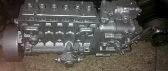
Fuel pump YaMZ-238
Let us briefly describe the principle of operation of the fuel supply system. The fuel pump supplies it to the injection pump through coarse and fine filters. In accordance with the operating mode of the power unit, the injection pump injects the working mixture into the engine cylinders through injectors. The fuel system circuit is designed in such a way that excess mixture flows back into the tank through the main pipes.
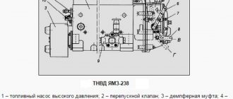
Operating principle of fuel injection pump YaMZ-238
The pump has compact dimensions and is located in the engine compartment on the plane of the power unit, between the rows of cylinders. The injection pump has eight sections (one for each cylinder) and a gear drive. The fuel pump, depending on the engine power, comes in several types, each of which has its own design features and adjustment method.
The operating principle of the injection pump is not complicated, but has certain nuances. To create primary pressure, the system is equipped with a fuel pump, which supplies the working mixture to the fuel injection pump chambers, with the plunger in the lower position.
As soon as the plunger begins forward movement, upon reaching a certain position, it opens the discharge valve to further supply the mixture and inject it. The pressure in the fuel chamber increases due to the upward movement of the plunger.
Be sure to read: Oil for walk-behind tractor
When the maximum pressure is reached, the nozzle needle rises and the working mixture begins to flow into the cylinder. As soon as the plunger reaches its final upper position, the pressure of the working mixture in the discharge circuit will begin to decrease sharply. As a result, the injector needle will return to its initial position and fuel injection will stop.
One of the most common fuel injection pump malfunctions is a worn oil seal. In this case, the repair is not difficult and you can do it yourself. On the Internet you can find a video with a detailed description of the working process.
Fuel pump diagram
Spare parts for Ural, Kraz, MAZ, Kamaz trucks. Engine parts YaMZ-236, YaMZ-238
__________________________________________________________________________
__________________________________________________________________________
YaMZ-238 diesel power system
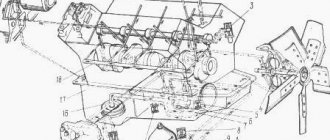
____________________________________________________________________________ The fuel equipment of the YaMZ-238 diesel engine of the MAZ-5516, MAZ-64229, 6303 and Kraz-255, 6510, Kraz-65101 vehicles is of a divided type. The fuel supply system of the YaMZ-238 engine consists of: a high-pressure fuel pump with an all-mode speed controller and a built-in corrector for adjusting the fuel supply, a fuel priming pump, injectors, coarse and fine fuel filters, low and high pressure fuel lines.
Rice. 8. Diagram of the YaMZ-238 A engine power supply system – suction line; B – low pressure; C – high pressure; D – draining excess fuel into the tank; 1 – fine fuel filter; 2 – nozzle; 3 – fuel coarse filter; 4 – fuel tank; 5 – fuel priming pump; 6 – high pressure fuel pump From the tank through the coarse filter, fuel is sucked in by the YaMZ-238 fuel priming pump and supplied to the fine filter and then to the high pressure fuel pump. The fuel injection pump YaMZ-238 of the MAZ-5516, MAZ-64229, 6303 and Kraz-255, 6510, Kraz-65101 vehicles, in accordance with the operating order of the cylinders, supplies fuel through high-pressure fuel lines to the injectors, which spray it into the engine cylinders. Through the bypass valve in the YaMZ-238 fuel pump and the jet in the fine filter, excess fuel, and along with it the air that has entered the system, is discharged through the fuel line into the fuel tank. The fuel that has leaked into the cavity of the injector spring is discharged through the drain pipeline into the tank. The pump is located in the camber of the YaMZ-238 diesel engine between the rows of cylinders and has a gear drive. The high-pressure fuel pump of the YaMZ-238 diesel engine is eight-section, according to the number of engine cylinders. Fuel priming pump YaMZ-238 The fuel priming pump of the YaMZ-238 diesel engine is a piston type designed to supply fuel from the fuel tank through coarse and fine filters to the high pressure fuel pump. The productivity of the YaMZ-238 fuel priming pump is 3-4 times higher than the productivity of the high-pressure fuel pump, which guarantees the stability of the fuel supply process from cycle to cycle. The design of the YaMZ-238 pump for MAZ-5516, MAZ-64229, 6303 and Kraz-255, 6510, Kraz-65101 vehicles is shown in Fig. 9. Fig. 9. Fuel pump YaMZ-238 1 – housing; 2 – piston; 3 – piston spring; 4 – sealing ring; 5, 16 – plugs; 6 – rod bushing; 7 – pusher rod; 8 – pusher; 9 – pusher retaining ring; 10 – cracker pushers; 11 – roller axis; 12 – roller; 13 – discharge valve; 14 – valve spring; 15 – sealing washers; 17 – cylinder body; 18 – cylinder; 19 – piston; 20 – rod; 21 – handle; 22 – protective cap; 23, 24, 25 – sealing rings; 26 – suction valve; 27 – valve seat The fuel priming pump of the YaMZ-238 diesel engine is mounted with three bolts on the left side on the body of the high-pressure fuel pump and is driven by the eccentric of the cam shaft through a roller tappet. In the housing 1 (Fig. 2) of the pump there is a piston 2, a piston spring 3, resting on one side against the piston, and on the other against a plug 5, suction 26 and discharge 13 valves, pressed to the seats by 27 springs 14. Cavity of the diesel pump housing YaMZ-238, in which the piston moves, is connected by channels to cavities above the suction and under the discharge valves. The piston is driven by a pusher 8 through a rod 7. The pusher roller rotates on a floating axis 11, locked by two nuts 10 against longitudinal movement. At the same time, the pusher blocks, moving in the grooves of the housing 1, protect the pusher from turning. Rod 7 moves in guide sleeve 6, which is screwed into the pump body using special glue. The rod and bushing are a precision pair. To pump fuel when the YaMZ-238 engine is not running, the pump is equipped with a manual fuel pump. This pump is used to remove air from the fuel system before starting the engine, as well as to fill the entire line with fuel during maintenance of fuel equipment. YaMZ-238 diesel injectors All parts of the YaMZ-238 diesel engine injectors of MAZ-5516, MAZ-64229, 6303 and Kraz-255, 6510, Kraz-65101 vehicles are assembled in housing 7 (Fig. 10). Rice. 10. Diesel injector YaMZ-238 1 – nozzle body; 2 – spray needle; 3 – spacer; 4 – rod; 5 – sprayer nut; 6 – spring; 7 – body; 8 – fitting with filter; 9 – cap; 10 – nut; 11 – washer; 12 – adjusting screw; 13 – spring plate; 14 – pin; 15 – slot filter A spacer 3 and a nozzle (mod. 335.1112110-50 and 204.1112110-50.01, respectively) are attached to the lower end of the YaMZ-238 injector body with a nut 5. The relative position of the nozzle body, spacer and sprayer is determined by pins pressed into the spacer. Inside the body 1 of the sprayer there is a shut-off needle 2. The body and the needle form a precision pair. The sprayer has five spray holes. The tightening force of spring 6 (injection start pressure) is adjusted by screw 12 screwed into the nozzle body. The screw is fixed with a nut 10. For the YaMZ-238 injector model 204-50.01, the tightening force of the spring 6 is adjusted by adjusting washers installed in the nozzle body. Fuel is supplied to the injector through fitting 8 screwed into the injector body. The slot filter rod 15 is pressed into the fitting. The fuel that has leaked through the gap between the needle and the nozzle body is removed from the nozzle through the cavity of the spring and holes in the adjusting screw and cap 9. Injector of YaMZ-238 diesel engines of MAZ-5516, MAZ-64229, 6303 cars and Kraz-255, 6510, Kraz-65101 are installed in the cylinder head glass. A copper corrugated washer is placed under the end of the nozzle nut to seal against gas breakthrough. Coarse fuel filter for YaMZ-238 engine Fig. 11. Coarse filter for diesel fuel YaMZ-238 1 – axle; 2 – cap; 3 – filter elements; 4 – flange; 5 – purified fuel outlet tip; 6 – fuel supply tip; 7 – filter cover; 8 – gasket; 9 – air release plug; 10 – drain plug The YaMZ-238 coarse fuel filter consists of a cover 7, a cap 2 and filter elements 3. The cap and the cover are connected by four bolts through a flange 4. The seal between them is ensured by a rubber gasket 8. The cap has a drain plug 10. Fuel in The YaMZ-238 diesel filter of the MAZ-5516, MAZ-64229, 6303 and Kraz-255, 6510, Kraz-65101 cars enters through the tip 6 and the cavity in the axis 1. Fuel purification is carried out in the settling cells of the filter elements 3, particles of mechanical impurities and drops water flows along the inclined walls of the disk cells into the collecting cavity of the cap 2. During operation, periodic drainage of sludge, washing of the cap and filter elements are provided. Fine filter for diesel engine YaMZ-238 Fig. 12. Fine filter for diesel fuel YaMZ-238 1 – drain plug; 2 – drain plug gasket; 3 – spring; 4 – filter element; 5 – cap; 6 – rod; 7 – cap gasket; 8 – cover; 9 – plug; 10 – jet gasket; 11.15 – jet valve; 12 – bolt; 13 – gasket; 14 – filter element gasket The YaMZ-238 fine fuel filter (Fig. 12) consists of a cap 5 with a rod 6 welded to it, a cover 8 and a filter element 4. A drain plug 1 with a gasket 2 is screwed into the rod from below. The seal is between the cap and The lid is secured with a paronite gasket 7. The cap and the lid are connected by a bolt 12, under the head of which a sealing washer 13 is placed. The replaceable filter element 4 is made of special paper or synthetic fabric. Spring 3 presses the element to the cover. The element is sealed at the end surfaces with gaskets 14. A nozzle valve 15 is screwed into the cover, which is sealed with a gasket 10. Through the nozzle valve, part of the fuel is drained along with the air entering the low pressure system. The jet valve is adjusted to an opening pressure of 20 - 40 kPa (0.2 - 0.4 kgf/cm2). At low pressure in the system, which can be observed during startup, of the engine of MAZ-5516, MAZ-64229, 6303 and Kraz-255, 6510, Kraz-65101 vehicles, the valve closes the channel and the fuel does not drain, the fuel supply to the ECU is improved. During operation, periodic drainage of sludge, replacement of the filter element, and washing of the cap are provided. Fuel lines of YaMZ-238 diesel engines Fig. 13. Diagram of the connection of fuel injection pump sections and cylinder injectors of the YaMZ-238 engine with high-pressure fuel lines. To supply fuel to the pump and injectors of the YaMZ-238 diesel engine and remove its excess, the engine has a system of low and high pressure fuel lines. YaMZ-238 low-pressure fuel lines are connected with hollow bolts or union nuts through tips attached to the ends of the fuel lines. The contact surfaces are sealed with copper washers 1.5 mm thick. YaMZ engines can be equipped with low-pressure polyamide fuel lines. The contact surfaces are sealed with aluminum washers 1.5 mm thick. The high-pressure fuel lines of the YaMZ-238 diesel engine of the MAZ-5516, MAZ-64229, 6303 and Kraz-255, 6510, Kraz-65101 vehicles (Fig. 13) have the same length for all engine cylinders. The ends of the fuel lines are set in the shape of a cone and pressed with union nuts to the fittings of the high pressure fuel pump and injectors. To avoid damage to the YaMZ-238 fuel lines from vibration, they must be secured using special brackets. To seal the common heads, high-pressure fuel lines are fitted with flanges.
_________________________________________________________________________
_________________________________________________________________________
_________________________________________________________________________
- Cardan shafts and power take-off Ural-4320
- Transmission gearbox Ural-4320
- Bridges Ural-4320
- Transfer case Ural-4320
- Steering Ural-4320
- Truck cranes and cranes based on trucks
_________________________________________________________________________
_________________________________________________________________________
- Cylinder block and cylinder head YaMZ-236 HE2, YaMZ-236 BE2
- Checking and adjusting YaMZ-236
- Power system and lubrication system YaMZ-236
- Driven and driven clutch discs YaMZ-236, 238
- Cooling and lubrication systems YaMZ-238
- Fuel injection pump YaMZ-238
_________________________________________________________________________
- Kamaz diesel engine
- Repair and adjustment of Kamaz power steering
- Kamaz-152 gearbox with divider
- Gearbox parts for Kamaz-5320 gearbox
- Kamaz transfer case and driveshafts
- Kamaz gearbox repair
- Clutch KamAZ-5320
- Construction of Kamaz-4310 drive axles
- Power steering MAZ-5551, 5549, 5335, 5336, 5337
- Front axle and steering rods MAZ-5551, 5549, 5335, 5336, 5337
- Clutch adjustment MAZ-5551, 5549, 5335, 5336, 5337
- Adjustment and repair of gearboxes MAZ-5551, 5549, 5335, 5336, 5337
- Repair and maintenance of the rear axle MAZ-5551, 5549, 5335, 5336, 5337
- Front axle parts and steering rods MAZ-5516, 5440
- Steering Maz-5516, 5440
- Details of driving axles Maz-5516, 5440
- Clutch device ZIL-130
- Repair of ZIL-130 gearbox
- Repair of rear axle ZIL-130
- Basic parts of the ZIL-130 engine
- Transfer case and power take-off ZIL-131
- Drive axles ZIL-131
- Steering ZIL-131
- Maintenance of ZIL-645 engine parts
Adjusting the injection pump YaMZ-238
All performance indicators of the power unit depend on the correct adjustment of the pump: power, productivity, efficiency, operational life. Therefore, all stages of the adjustment process are extremely important and should be performed only by highly professional specialists using technological equipment.
Often, the fuel injection pump of the brand being described is adjusted at the following stands:
- NTs-108 (Czechoslovakia).
- Star-12.
- Minor-8.
Adjustment of fuel injection pump parameters on a bench is necessarily carried out with injectors that will work with it on the engine. The order of work during adjustments is very important, since violation of the sequence of activities performed is the cause of incorrect operation of the pump in the future.
At the initial stage, the fuel supply between the pump sections is adjusted, after which the optimal injection value is adjusted. The supply of the working mixture is adjusted using a momentoscope, while the automatic advance clutch must be removed. The uniformity and amount of mixture supply to the fuel injection pump sections is regulated using a cam shaft. The final stage of setup is to lubricate all interacting elements.
Connection diagram
When installing the injection pump on the power unit, you must pay attention to ensure that the marks of the drive coupling half and the injection advance are at the same level. It is necessary to correctly set all axial clearances between the cams and the ends of the couplings and coupling halves before finally tightening the mounting bolts. The size of the gaps should not exceed 0.3 mm. After installing the adjusted fuel injection pump on the engine, the fuel supply lines should be connected.
The main feature of the high-pressure fuel pump connection diagram is the correct sequence of connecting the fuel lines and injectors.
Source
MODEL 173 HIGH PRESSURE FUEL PUMP
The fuel pump assembly is shown in Fig. 2.
The high-pressure fuel pump in one unit combines the speed regulator 5, the fuel priming pump 9 and the damper clutch 3.
DEVICE AND OPERATION OF HIGH PRESSURE FUEL PUMP
The high-pressure fuel pump consists of sections, individual pumping elements located in a common housing.
The number of sections is equal to the number of engine cylinders.
The design of the high pressure pump section is shown in Fig. 3.
In the pump housing 1 there are housings of sections 15 with plunger pairs, discharge valves and fittings 11, to which high-pressure fuel lines are connected.
What does the system consist of?
The fuel YaMZ 650 includes main parts. responsible for its functionality, and additional elements. The electronic control unit receives information from sensors and the unit responsible for controlling the machine. Taking into account the settings, the unit controls the injection of fuel fluid and some additional functions, for example, the fan that the engine is equipped with. The electronic element provides the driver with data on the state of the fuel injection system using special lamps and light signals located on the dashboard.
The coarse fuel filter is complemented by a moisture separator, a hand pump and a replaceable part. The fine filter is a full combustion type and is equipped with a pair of filtration parts in combination with a device that automatically heats the fuel liquid in winter. Another element - a high-pressure fuel pump is complemented by a pair of plunger sections and a gear drive element. The system ramp is responsible for the connection between the injectors and the main pump. It is complemented by a pressure sensor and a restart valve that protects high-pressure circuits by discharging fuel fluid into the tank.
In addition to the main elements, the system is equipped with an electrically controlled nozzle, which includes an electric valve that controls the opening and closing of the spray element. It cannot be repaired, but it is necessary to replace the seal gaskets after all dismantling work. The fitting for supplying fuel to the nozzle is supplemented with a device that protects it from rotation due to two sealing balls. Such a fitting must be changed during dismantling work in the same way as the seal. The phase sensor is of the inductive type and is responsible for sinusoidal voltage.
The frequency of the signal from the sensor is proportional to the speed at which the motor element rotates, while the flywheel is equipped with 58 cavities. The sensor for pressure and temperature from the intake manifold element is complemented by two measuring parts, when a voltage of 5 V is present it produces an output voltage between 0.5-4.5 V. The sensor for oil pressure produces a voltage of no more than -7 bar when supplied at 5 V. Another fuel filter element clogging sensor is activated if the pressure difference between P1 and P2 can reach 3 bar. Data on filter contamination is displayed on the screen only when the engine is warm.
An additional, but no less important element is the clutch for activating the fan. It includes a speed sensor and is complemented by an electric viscous coupling control valve. The electronic computing part is capable of controlling the viscous coupling using an electric valve as one of the engine options is in demand, for example, temperature, mode for reduced efficiency, activation of the air conditioner or heater.
The operation of the system must be carried out according to the rules in the presence of high injection pressure of up to 1400 bar in combination with high voltage current. If it needs to be disassembled, the system is first cleaned and all precautions are taken to prevent contamination from getting inside.
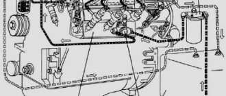
System Description:
Components of the electronic fuel injection system “COMMON RAIL SYSTEM 2”:
- electronic engine control unit with cooler (ECU) (1) (650.3763010);
- fuel coarse filter (2) (installed by the consumer);
- fine fuel filters (3) (650.1028010 - assembled);
- fuel priming (4);
- fuel pump metering solenoid valve (5) (650.1111674));
- fuel shaft speed sensor (phase sensor) (6);
- fuel pump (7) (650.1111005);
- ramp (8) (650.1112552);
- bypass (9);
- injectors (10) (650.1112010);
- rail pressure sensor (11) (650.1130540);
- oil pressure sensor (12) (650.1130552);
- temperature sensor in the cooling system circuit (13) (650.1130556);
- pressure and air temperature sensor in the intake manifold (14) (650.1130548);
- engine speed sensor (15) (650.1130544);
- fuel pressure and temperature sensor (16);
- hazard warning lamp (18) (ChekEngen).
Components of other auxiliary functions:
- fan shut-off clutch (17);
- exhaust system flap.
Information received from sensors.
The vehicle's electronic control unit (19) exchanges information with the engine ECU (1) via a loop (20).
Hydraulic circuits:
- (A) - suction system;
- (B) - low pressure system;
- (C) - high pressure system;
- (D) - return system to the fuel tank (21).