To assess the volume of repair work, leveling (geodetic survey) of crane tracks is carried out. Using the data obtained, horizontal and vertical deviations are determined. The actual number of “points” that require straightening and repair is established.
Height adjustment can be done in two ways:
1. The method of raising/lowering the rail;
2. The method of raising/lowering a crane beam with a rail attached to it.
Lifting is carried out due to the backing material, which are metal plates 5 - 30 mm thick.
Track straightening, if unacceptable deviations from parallelism are identified, is carried out by dismantling the fasteners and installing the rail or I-beam in the design position.
The straightening method is chosen based on the degree of wear and the type of crane track; in the case of a support track, the type of crane beams: they can be metal or reinforced concrete.
What is the crane runway straightening procedure?
Crane runway straightening is a procedure for displacing elements of crane mechanisms. Here we are talking about adjusting load-bearing beams, guides, rails, and support columns. As a rule, the straightening process is performed during repair or installation of the crane runway structure.
Before straightening, the mechanic needs to level the equipment, take measurements in order to find out the plan-height deviations and develop adequate methods for their elimination. Straightening of the crane runway is performed exclusively in an unloaded state. All measurement readings must be entered into a special journal for recording leveling work.
Deviations of the rail track from the norm occur in the following situations:
- when the equipment has not been put into operation for a long time;
- under constant dynamic loads;
- in the event of an emergency or accident.
If deviations are found, specialists should carry out straightening work. Mechanics should perform calculations of repair methods and estimate the dimensions of rail ties and pads. When carrying out straightening, it is necessary to take into account the readings of previous periods, in particular, to analyze the areas of lining subsidence and deformation of the upper structures.
To carry out repairs, you must:
- dismantle the tracks;
- identify the causes of the malfunction;
- analyze the state of serviceability of metal structures and electrical equipment;
- eliminate all faults;
- collect all the guides.
All repair work must be carried out based on the technical condition of the crane runway, based on a plan for eliminating defects.
When performing straightening work, you should:
- carry out track straightening work;
- carry out manipulations to adjust all gaps;
- perform correct installation of grounding conductors.
If there is damage to the crane rails or the sand and gravel cushion, it is necessary, depending on the degree of deformation, to partially or completely replace the failed elements. Restoration of the lining is carried out using granulated slag, sand, gravel or crushed stone.
It is worth noting that carrying out repair and straightening work is impossible without a preliminary analysis of geodesy, which will allow us to determine the degree of deviations that have arisen. This is precisely the problem that preliminary leveling solves. After all stages of repair work have been carried out, the adjusted structures must be firmly fixed using bolts and locknuts. You should also ensure that the new fasteners are fixed at an identical distance to the old connections.
Work order
The general technology of track straightening involves three stages:
- preparatory,
- basic,
- final (final).
Before considering each of them in detail, we note that in a normal situation the problem is solved by a team of 7 people, which, in particularly complex or urgent cases, as well as when using optics, can be expanded to 8-10 fitters of the 4th category.
The initial stage of preparation comes down to the study of deflection arrows - the curvature is measured along a chord 20 m long - and to calculations based on the data obtained, carried out using the Pashkarpov method.
Having received the necessary numbers, in accordance with them you need to drive in temporary reference points - so that after alignment they are located at the same and constant distance from the outer side of the sole. For this, wooden pegs with a cross section of 3-4 cm in the wide part, 25 cm long, with a hewn edge, which should be placed in the direction opposite to the track vector, are best suited. They should be placed strictly opposite the division points, and in such a way that the distance from their tip to the rail support is equal to the template with a tolerance up or down exactly by the amount of shift.
Specifications
They fully regulate the fastening of crane track rails to steel beams for organizing the movement of electric overhead cranes and are dictated by GOST 4121-76. According to this standard, transport lines created in this way can be operated in light, medium and even heavy duty. Objects for laying lines are allowed to be very different, up to open and fairly long overpasses.
The maximum calculated seismicity is 9 points on the MSK-64 scale, the ambient temperature can reach -65 degrees Celsius.
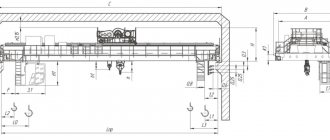
They also set the center distance between the supporting structure and the central installation point. It, along with other important geometric parameters, is presented in the drawing and table below.
| Rail type | Mounting unit brand | Distance between axes Ah, mm | Planks | screw | Bolt | Washer | |
| clamping | stubborn | ||||||
| KR70 | 70 | 95 | P1 | U1 | M 24.4 GOST 15526-70 | M 24x46 GOST 15589-70 | 24.02 GOST 11371-78 |
| KR80 | 80 | 100 | P2 | ||||
| KR100 | 100 | 110 | P1 | U2 | |||
| KR120 | 120 | 120 | U3 | ||||
| KR70 | 70HL | 95 | P1HL | U1HL | M 24.4 GOST 5915-70 | M 24x46 GOST 7798-70 | |
| KR80 | 80HL | 100 | P2HL | ||||
| KR100 | 100HL | 110 | P1HL | U2HL | |||
| KR120 | 120HL | 120 | U3HL |
Important Reliable all-terrain vehicles Sokol are produced from auto parts
When deciding which attachment point for crane rails to reinforced concrete beams to choose, remember the connectors. In the case of fixation elements, the following rule applies:
l, that is, the estimated length of the bolt, must be taken based on the following ratio:
(80 + b) mm – if preference is given to KR70-100 profiles;
(85 + b) mm – if KR120 will be used;
and in this formula:
80 and 85 – the total (total) thickness of the elements, already taking into account that nuts, washers, and other components may be tilted, and taking into account the effect that is observed in this case; b – average thickness of the supporting structure, presented in millimeters and taken in the central part of the upper chord.
Main activities:
• installation and maintenance of overhead and gantry cranes; • major, current and emergency repairs of bridge, gantry cranes and beam cranes; • design and manufacture of crane (crane) tracks; • installation, repair and maintenance of crane (crane) tracks; • production and installation of crane metal structures; • repair of metal structures and electrical equipment of lifting equipment; • modernization of electric drives of overhead cranes; • modernization of control systems for overhead and gantry cranes.
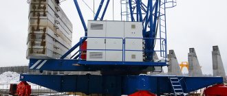
Railway crane
A railway crane on rails is a fully rotating, self-propelled mechanism on railway rails. The devices are used for loading work in warehouses of reinforced concrete panels, unloading blocks at a construction site, and installation during the construction of industrial buildings.
In order to be able to service warehouses for bulk materials, railway devices are often supplemented with a grab.
The railway unit consists of:
- rotating platform;
- high-tech boom;
- durable frame;
- reliable power unit;
- mechanism systems;
- driver's cabin;
- rotary support system;
- worker node.
Modern rail-mounted cranes with a lifting capacity of less than 15 tons are used without outriggers. Units that lift loads exceeding 15 tons operate on supports. The units can perform the following functions:
- lifting load;
- rotation of the unit;
- movement of the device with a load;
- change in boom radius.
Rail-mounted jib cranes can move independently or be attached to railway trains.
Laying crane UK-25 9-18
The UK-25/9-18 laying crane is used for assembling and dismantling railways with rails weighing up to 18 tons, length up to 25 m when laying or repairing railway tracks.
The tracklayer UK-25/9-18 has the following technical characteristics:
- Traction force - 100 kN.
- Diesel power is 121 kW.
- Track width - 1435, 1520 mm.
- The lifting capacity of the unit is 18 tons, the platform is 40 tons.
- The length of the railway link is 25 m.
- Speed - 80 km/h (during transportation), 20 km/h (self-propelled).
- Dimensions: 43330x6820 mm.
- Weight - 102 tons.
Laying crane UK-25 25
The UK-25/25 track-laying crane has a high lifting capacity and is equipped with a telescopic rotary truss. The unit has the ability to telescopically rotate the boom. The mechanism is used for the installation of railway tracks. It can lay links 25 m long and weighing 25 tons. The unit is self-propelled. When performing work, it is the main machine of track-laying complexes.
The tracklayer has high productivity and load capacity. It is universal in use due to the ability to rotate the boom in plan. This makes it easier to lay tracks around turns. The design uses serial components and parts, which ensures the strength and reliability of the unit.
Specifications:
- Lifts loads up to 25 tons.
- The speed when the unit is fixed to the train cars is 80 km/h.
- The self-propelled unit reaches speeds of up to 15 km/h.
- The radius of the possible curve is 180 m.
- The boom rotation angle is 3º.
- Dimensions - 44.3x3.4x5.1 m.
- Weight - 130 tons.
Working with us is very easy!
Receiving an application and consulting by phone to approximately determine the scope of work and its cost, agreeing on a preliminary agreement to begin work on the order.
Free visit of a specialist to inspect the conditions at the site of the proposed work and take the necessary measurements. We clarify the task (type of crane, lifting capacity, span, lifting height, type of crane track, type of power supply. We promptly prepare a detailed technical and commercial proposal indicating the cost of materials and equipment, cost of work, delivery time for equipment and completion of work. Together with the customer, we optimize the cost and We are preparing a contract.
We prepare designs for metal structures and crane tracks, and draw up a “Project of Works”. We purchase the materials and equipment required to complete the work. We begin to carry out work upon request, carry out installation, repair work or maintenance of lifting equipment and crane tracks.
We complete installation or repair work, proceed to technical inspection of finished lifting equipment with static and dynamic tests with test loads. We prepare technical passports of objects, sign final documents on the execution of the order.
Use in industrial areas
They are required to maintain their factory specifications throughout the entire period of operation at such critical facilities as:
- enterprises in the metallurgical and construction sectors, as well as related industries - plants and factories characterized by large volumes and/or a wide range of production;
- transport interchanges and large warehouses - with constant flow loading and unloading operations;
- as well as for moving functional units of large-sized and other objects that require a specific approach and the use of equipment with a special gripping mechanism;
- and for commissioning new or modernized industrial facilities - with the organization of technological processes.
Additional uses of sleepers
They are used in the same cases as full-size support systems, but with one important caveat: everywhere except for main road surfaces. Their laying on main lines is impractical, since it will take considerable time to stabilize the rail threads, and in modern conditions this is usually simply not available. But they are quite in demand in the following situations
For driveways of enterprises
In terms of its load intensity, the internal transport network of even the largest plant is still incomparable to a standard railway route, and therefore is quite rightly considered an inactive area. This means that reinforced concrete or wooden sleepers of types 1 and 2 (the dimensions of which we gave above) are quite suitable for laying it. Moreover, they will even be a priority solution in terms of practicality, since they involve less material consumption, resulting in minimization of construction costs.
For station tracks
They also find their application in these areas, characterized by relatively low traffic speeds. Although there is an important nuance here: when laying, shortened ones should be alternated with whole ones, and to stabilize the width of the canvas, metal ties should also be used. The same rule applies to access lines. Regular testing and statistics confirm that the measures described are sufficient to ensure proper operational safety of the web.