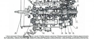
Screw in stud 7 by 8 - 9 turns, secure with nut 8.
The 1st gear drive gear is integral with the shaft 51, and the 2nd gear drive gear is rigidly connected to the shaft. In the body of the forks 13 there are leashes 12, 16 on which the forks are fixed
To prevent simultaneous activation of gear couplings 34 and 53, blocking balls 6 are installed in the holes of the gearbox housing.
Search on the site. On the handle of the gearbox control lever 3 there are buttons 10, 11 and LED indicators 13,12 for turning on the lowest and highest stages of the gearbox, respectively.
Accordingly, when the desired speed is turned on, the gear selector lever is first set to the required position, and then the range selection lever. But, as it is not difficult to understand, nothing lasts forever under the sun, much less under the Krasnodar or Tambov sun, and equipment, no matter how good it is, needs current and major repairs. Violence, self-harm.
Tires for trucks and buses. This six-cylinder engine, the displacement of which is 7. The MTZ model wheeled tractor is a universal representative of equipment used for row crop work. Among other things, it also serves as a sound absorber. MTZ 82.1 gear diagram. How to operate a gearbox correctly
More on the topic: do-it-yourself MTZ-82 guru repair video
How to turn on the gearbox on MTZ 1221
The gearbox is one of the most important components of any vehicle. It is the gearbox that is responsible for changing the direction and speed of movement. For a tractor with its high fuel consumption and significant load on the power plant, the correct choice of program allows not only to reduce fuel consumption, but also helps to extend the service life of components and assemblies.
In order to operate the gearbox in optimal mode, timely identify faults and carry out repairs, it is necessary to present a diagram of the arrangement of individual elements and the principles of operation of the unit.
Need for gearbox repair
When is gearbox repair required? Special equipment should be diagnosed if the transmission starts to switch off spontaneously. Another problem that a tractor owner may encounter is difficult lever movement.
Repair of the MTZ gearbox may consist of replacing:
- oils;
- backstage;
- bearings;
- grooves and other components of gearbox consumable spare parts.
Repairs may involve tightening loose fasteners, which may cause noise from the box. Also, the cause of noise is wear of the bearings. In parallel with this, overheating of the gearbox may occur. To replace the bearings, the oil is drained, the box cover is dismantled, then the gearbox itself, after which it must be disassembled.
When gear teeth wear, a characteristic sound is noted. In good condition, no knocking noises should be heard from the gearbox.
In some cases, it is necessary to flush the existing oil strainer. Washing should be done in clean diesel fuel. One of the frequent breakdowns is the presence of a low oil level in the box. It should be on the bottom edge of the existing inspection hole. The fuel level is checked when the equipment is standing on a level surface. In this case, the engine must be warmed up. Add liquid through the filler plug on the top cap.
Gearbox MTZ-1221: shift diagram
In the Belarus tractor, the gearbox control mechanism consists of two components: a gear shift unit with synchronizers and a range switching device. Each of these units has its own separate control lever in the tractor cab.
Accordingly, when the desired speed is turned on, the gear selector lever is first set to the required position, and then the range selection lever.
The diagram for switching gearbox operating modes is shown in the photo located on the website. Roman numerals indicate the positions of the gear lever, and Arabic numerals indicate the positions of the range selection lever.
MTZ gearbox design and switching diagram.
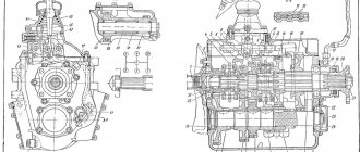
The peculiarity of the Minsk transmission is that the primary and secondary shafts are located on the same axis in a single housing. The intermediate shaft and the first gear shaft are located parallel to the primary and secondary shafts.
The gears are mounted on the shaft splines. In addition to the spline, there is a reduction gearbox on the input shaft.
| Power on speed (km/h) | |||||
| Forward speeds | Reverse speeds | ||||
| 1 | 2 | 3 | 4 | 1 | 2 |
| 2,82 | 5.48 | 8,95 | 17,45 | 4,96 | 15,75 |
| 3,42 | 6,64 | 10,85 | 21,1 | 6,05 | 19,12 |
| 4,14 | 8,01 | 13,10 | 25,5 | 7,28 | 23 |
| 4,96 | 9,62 | 15,74 | 30,8 | 8,67 | 28 |
Model description
MTZ 1221 technical characteristics of which, we will look at a little later, are class 2.0 special equipment. Purpose:
In addition, MTZ 1221 is used in public utilities, construction, and industry. Used for work in the forestry industry.
MTZ 1221 photo of the equipment you see works in different climatic zones and on different soils. Including serving soils with low bearing capacity.
Due to the possibility of using a wide range of attachments and additional equipment, it aggregates with a large number of special class 2 equipment. It can work with some class 3 machines.
The MTZ 1221 tractor video, the work presented in the article, gives an idea of its capabilities and potential. Simplicity of design, reliability of components and mechanisms, combined with high productivity make it a reliable and indispensable assistant in many areas of the economy.
In addition, the MTZ 1221 tractor consumes a minimum amount of fuel and lubricants. There are no problems with its repair. Minor problems can be carried out in the field, without having to constantly move equipment to stationary workshops.
Possible faults
A tractor gearbox is a device characterized by wear resistance and reliability. The transmission can last for 3 years and still work every day. So that repairs do not have to be done earlier, you need to observe the correct operating mode of all elements and components. It is important to remember that the functionality of the tractor gearbox is influenced by various factors:
- oil quantity, pressure;
- cleaning elements for filtration, centrifuge. It must be carried out on time;
- compliance with the regime according to which the clutch is adjusted;
- condition of the drive axle located in front;
- correct gear adjustment.
General technical indicators
Please note that these are general technical indicators of MTZ 1221; the characteristics of the condition of components and assemblies will be given below. Table 1 - MTZ 1221 technical characteristics
| Total information | Unit change | Indicators |
| Weight | kg | 5300 |
| Operating weight indicators | kg | 5730 |
| Maximum permissible weight | kg | 8000 |
| Base | mm | 2760 |
| Length | mm | 4500 |
| Width | mm | 2300 |
| Height | mm | 2850 |
| Smallest turning radius | m | 5,4 |
| Clearance | mm | 480 |
| Tank | l | 140 |
| Maximum speeds | km.h | 35 |
| Working speed | km.h | 15 |
After considering the technical characteristics common to the MTZ 1221 tractor, we will get acquainted with the power unit installed on it and find out the condition of the braking system. Let's go through the installed gearbox and electrical equipment. Video of MTZ 1221 in the field, see its potential at the beginning of the article.
How repairs are made
If it is necessary to carry out repair work, usually the whole process begins with dismantling the gearbox, disassembling the units, components and cleaning them. Subsequent actions will depend on the breakdown and its nature. If we talk about the most common breakdowns, then these are:
- impossibility of fully engaging the transmission. The reason may be wear of the gearbox cover elements located on top;
- damage to the gears that belong to the input shaft, or their wear. This malfunction can be caused by insufficient oil pressure or an incorrect clutch;
- nuts are broken, bearings are damaged. The reason is that the gearbox engagement is incorrectly adjusted.
If it was not possible to restore the unit’s functionality, then you should buy a Belarus-1221 gearbox (gearbox) and have it installed at a service station.
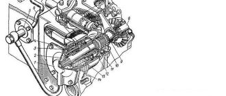
Wheel reducers
Wheel reducers MTZ-1221 Belarus of planetary-cylindrical type - designed to transmit and increase torque from the FDA differential at different angles of rotation of the front driving steered wheels.
The gearboxes are mounted in housings 35 and connected to the axle beam using axes 3 (Fig. 29) and can be rotated relative to the FDA beam on 2 bearings 9. The axles are connected to the wheel gear housing using bolts 4.
To adjust the angle of rotation of the wheel gearboxes, screw 38 and locknut 37 are used. Lubrication of the pivot axles 3 (Fig. 29) is carried out through oil nipples 6 installed on the axles.
The oilers are protected from dirt by rubber caps 5. To prevent dirt from getting into the pin bearings, cups 8 with rubber sealing rings 7 are installed in the bridge beam sleeves.
Adjustment of the bearings 9 of the kingpin is carried out by spacers 2, located only under the upper axles 3. Wheel gear 1 (Fig. 29) and consists of a double joint, cylindrical and planetary gears, and control levers for turning the front wheels.
The double hinge 24 (Fig. 31) is connected to the differential PVM MTZ-1221.2 Belarus by means of a semi-axial shaft with splined ends 13 (Fig. 29) on one side, and on the other – to the drive gear 17 (Fig. 31) of the spur gear.
The drive gear is mounted on two tapered roller bearings 18. One of them is installed in the bore of the gearbox housing 35, the second - in the sleeve 22.
The double hinge is fixed in the gear with a washer 15 and a bolt 14 with a bending plate. Bearings 18 are adjusted using spacers 21, which are installed between the cup and the gear housing.
The drive gear of the wheel reducer meshes with a gear block (driven spur gear) 34, the second crown of which is the sun gear or the drive part of the planetary gear set.
The driven part of the planetary gear set associated with the tractor wheel is the wheel flange, which is rigidly connected through splines to the carrier 5, three satellites 11, and the braked gear that receives the reactive torque is the epicyclic gear 12.
The epicyclic gear is installed in the gearbox cover and is secured against rotation by 3 pins 13. A sealing gasket is installed between the cover and the gearbox housing.
The sun gear is mounted on the wheel flange on a double-row tapered bearing 33, which is fixed on one side by a thrust ring 36 in contact with the carrier, and on the other by two retaining rings 31, 32. The satellites rotate on axles 7 installed in the carrier bores 5.
The satellite bearings are cylindrical rollers 8. One track of the rollers is the ground surface of the axis 7, and the other is the ground internal surface of the satellite 11.
How to disassemble the MTZ-80 box
Depending on the external signs of a malfunction, the gearbox must be partially disassembled or completely dismantled. The sequence of actions for complete dismantling of the MTZ gearbox in the repair scheme described in the instructions for the tractor provides the following steps:
- transmission oil drain;
- disconnecting the box assembly from the tractor body;
- disassembling the gearbox.
If a number of transmission problems are detected, you can disassemble without complete dismantling; this method is provided for unclear gear shifting, when at the first stage it is enough to dismantle the transmission control knob and check the condition of the unit.
Disassembling the MTZ-80 gearbox lever
You can check the suitability of the shift knob for further use without dismantling the gearbox, for which you need to perform the following steps:
- remove the lever by first removing the floor and disassembling the hinge socket;
- remove the plate with forks, visually determine which of them require replacement;
- inspect the suitability of the gear shift knob for further use;
- if the forks are bent and loose, and their working sides are not parallel, it is necessary to disassemble this unit and replace the worn parts.
Such repairs can eliminate only part of the possible problems associated with poor engagement and gear shifting. A complete inspection of the unit requires complete disassembly of the gearbox.
Disassembly procedure
In addition to keys and screwdrivers, the following fittings are required to remove the tractor gear shift mechanism:
- puller;
- hammer;
- metalworker's beard (beater);
- bronze knockout.
After disconnecting the assembly from the body and dismantling the plug block, you should:
- remove the retaining ring and gear from the input shaft, then remove the second ring and dismantle the bushing and gear No. 4;
- Having previously knocked out the pin, remove the internal PTO drive shaft (power take-off shaft);
- Having unscrewed the bolts and removed the socket, remove the second range drive gear complete with the cup and bearings from the housing;
- remove the input shaft to facilitate disassembly of a manual transmission operating according to the scheme (9F+2R);
- remove the intermediate shaft;
- remove the secondary shaft;
- prepare to remove the reverse and low gear shaft by removing the retaining ring and bearings;
- remove the reverse and low gear shaft from the housing;
- press out the bearing cup.
After removing the shafts from the gearbox, remove the gears from them and disassemble the remaining parts, removed entirely.
Defects of gearbox parts
After complete disassembly of the transmission, it is necessary to visually inspect all components and make a decision on their suitability for further use. In order not to miss metal defects, it is recommended to wash the components in kerosene or diesel fuel and dry them before inspection.
Recommendations for rejecting box elements:
- The housing must be replaced if cracks are detected.
- It is necessary to replace with new broken glasses in the body of the box.
- Instead of bent forks, as well as with non-parallel cheeks, new ones should be installed.
- Bearings should be checked by rotating the outer race relative to the inner race.
- You cannot install a gearshift lever with a worn tip.
You can begin installing the gearbox only after checking all the parts and obtaining new ones to replace those unsuitable for use.
Design of the MTZ 1221 tractor
Let's take a closer look at the power unit, gearbox and electrical equipment of the MTZ 1221 tractor.
Power unit
The tractor is equipped with a turbocharged diesel power unit. The location is in a row. The number of cylinders is six. The engine is characterized by low oil and diesel consumption. The diesel engine meets all necessary requirements for exhaust gas emissions into the atmosphere. The unit is omnivorous and can run on domestic and imported fuel. Table 2 - Engine MTZ 1221
| Engine model | D-260.2 |
| Power, kW (hp) | 96 (130) |
| Rated rotation speed, rpm | 2100 |
| Rated rotation speed, rpm | 2100 |
| Number of cylinders | 6 |
| Cylinder diameter/piston stroke, mm | 110/125 |
| Working volume, l | 7,12 |
| Maximum torque at 1400 rpm, N.m (kgf.m) | 500 (51) |
| Specific fuel consumption at rated power, g/kWh. (g/hp.h.) | 226 (166) |
| Torque reserve factor, % | 20 |
| Fuel tank capacity, l | 160 |
Transmission
MTZ 1221 has a 16/8 gearbox. Step version, with constant mesh gears. Switching occurs using synchronizers. Closed clutch. Permanent type. Double-disc friction system.
Figure 1 — MTZ 1221 gearbox shift diagram.
Electrical equipment
Figure 2 - Assembly units of equipment, electrical diagram of the MTZ 1221. The operating diagram of the MTZ 1221 includes:
The MTZ 1221 device we are considering is equipped with disc service brakes. Operating principle: load on the rear part with subsequent transfer of force through the FDA drive to the front wheels.
The parking brake is disc, synchronized with the service brakes. The system is considered reliable and balanced in terms of the dimensions and weight of the equipment, and is designed for additional loads of towed devices.
Figure 3 - Electrical diagram of MTZ 1221.
Kubota minitractor - universal and practical, technical specifications, videos, reviews and price.
Minitractor Caliber MT 120 here.
Diesel mini tractor, its features and price here.
Electrical equipment diagram Belarus-1221 – Tractor diagrams BELARUS-1221 – Beltract – MTZ-80.RU
What is an MTZ electrical circuit?
Let's look at what the electrical equipment diagram of a Minsk tractor consists of. One of the advantages of Minsk technology is the use of high-quality electrical wiring, based on the fact that metal parts are designed to act as mass. The advantages of such electrical wiring MTZ-1221, 80 or 82 include:
- reduced number of wires;
- simplified approach to maintenance.
But you need to take into account that wiring requires constant care and monitoring.
This will help monitor the serviceability of the wires, their insulation, and the reliability of the fastenings. If damage to the electrical circuit of the MTZ-80 or 1221 tractor is not detected in time, a fire, insulation damage, failure of electrical circuits, etc. may occur.
Let's look at the electrical equipment of Belarus tractors and a description of its operation.
The electrical circuit of MTZ-1221, 80 or 82 has the following characteristics:
- It has a polyvinyl chloride colored surface with low voltage.
- Additional elements are connecting panels, connectors, and wires that can be mounted in bundles. For example, such a half-move is applied to wires in MTZ-82.
- The PS 300A-100 socket is located on the rear wall of the operator's cabin and has 7 contacts.
- The socket is intended for all work where electricity is needed, including when transporting goods.
- Connection to the socket is made via a plug.
- If the need arises, you can connect the wiring harness from other units. Both the plug and the socket have special markings that help you understand where the wires are connected.
Trouble-shooting
Table 3 shows the classic malfunctions of the MTZ 1221. Table 3 - Malfunctions of the MTZ 1221 tractor and their elimination
| Malfunction | Elimination |
| MTZ 1221 front axle malfunction | |
| Insufficient traction of the front drive axle | |
| The drive clutch does not transmit torque: | |
| There is no oil pressure in the clutch booster. | Disassemble and wash the distributor parts. |
| Drive clutch slipping. | Check and adjust the pressure in the transmission hydraulic system (9...10 kgf/cm2). Replace worn discs. |
| Malfunctions in the electrical circuit of the FDA control. | Identify and correct problems. |
| Insufficient torque transmitted by the clutch due to oil leakage in the hydraulic system: | |
| Wear of rubber sealing rings. | Replace the rings. |
| Wear of piston rings and clutch drum. | Replace the rings. |
| Wear of the mating surfaces “cage – drum hub”, “drum – piston”. | Replace worn parts. |
| Malfunction of turning on the front axle MTZ1221, does not work in automatic mode | |
| The adjustment of the automatic switch on sensor is incorrect or faulty. | Adjust the switch position or replace it. |
| Hydraulics MTZ 1221 malfunctions | |
| The loaded hitch does not lift or its lifting is slow | |
| The malfunction appears as the oil in the hydraulic system warms up; the pump is faulty. | Check pump performance. If the efficiency pump is less than 0.7, replace the pump. |
| The malfunction occurs at any oil temperature - the unloading valve is clogged. | Remove the distributor regulator, remove the bypass valve, wash it and the housing in diesel fuel. |
Reviews
Ivan, Belgorod region:
A Russian-assembled machine is used (Saransk). The tractor engine heats up in hot weather, since the standard radiator from the MTZ-80 does not provide heat exchange. Frequent breakdowns of power take-off shaft elements due to design flaws.
The tractor was used to remove timber. In terms of cross-country ability, no differences from the Ural all-terrain vehicles were found. When installing the front bucket, the machine was used to transport sand used in road construction. The machine easily copes with the work, but the fuel consumption is high. Rear attachments are slow to operate in the winter due to thick oil in the lines and cylinders. Due to the constant load, breakages of the front axle stocking fastenings to the side members, as well as breakage of the gearbox gears, were observed.
main gear
The main gear is a pair of bevel gears with a spiral tooth. The main gear drive gear 36 is installed in a cup 29 on two tapered roller bearings.
The tension in the bearings is adjusted using adjusting washers 30, after which they are tightened with a nut 33.
The driven gear 19 is mounted on splines and the centering belt of the differential housing 18 and is secured against axial movements by a nut 20.
Adjustment of the main gear engagement is ensured by gaskets 28, 15 installed between the flange of the drive gear housing and the FDA housing, as well as between the left and right sleeves and the FDA housing, respectively.
Before adjusting the engagement, the differential bearings are adjusted, which is carried out using spacers 15. The hole for plug 25 is used to check the adjustment of the engagement of the main gear.
Oil leakage from the cavity of the main gear and the bridge beam is prevented by cuffs and rubber rings installed in the cages, sleeves and in the drive gear housing.
To prevent the creation of oil back-up in front of the drive gear cuff, an oil-removing ring 31 is installed at its splined end. Helical grooves are cut along the outer diameter of the ring. In the cage 12 there is a sliding bearing with cross grooves.
Box MTZ-80 assembly diagram
To eliminate problems when assembling the box of tractors of the MTZ-80/82 family, it is disassembled in a sequence that, when done in the reverse order, will allow you to obtain a technically complex unit without any problems. After discarding unsuitable parts and obtaining new ones, you should check that all bushings, gears and other parts comply with the standard dimensions specified by the manufacturer.
Gearbox bearings: type, dimensions, bearing numbers
The transmission of MTZ tractors uses several dozen standard sizes of these components. Most of them are single-row ball or needle type. The most popular sizes are also used in other components of agricultural and road machinery.
The table shows the range of common bearings used in gearbox assembly.