Category: KAMAZ
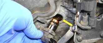
- Where is the speed sensor located?
- How the speed sensor works Contact sensors
- Non-contact sensors
The KamAZ brake system is thought out to the smallest nuances, since the technical condition of the vehicle and the possibility of safe driving depend on it. The installed KamAZ speed sensor is an important device, as it allows you to monitor the technical performance of the vehicle.
Where is the speed sensor located?
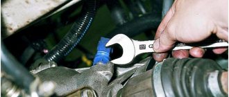
In most cases, the sensors are located at the gearbox and are connected by a special drive to the speedometer, the data of which is read to determine speed and mileage.
Thus, it is advisable to find functional units taking into account the layout of a specific KamAZ model and the specifics of the technical system. The devices have different designs, since the influence of the location of the unit is noted.
Contact sensors are considered less reliable due to the interaction of spare parts and constant rotation. However, such devices are often used, as they are installed instead of a mechanical speedometer drive and allow you to modernize brake systems. Contact models are characterized by optimal reliability.
Sometimes on KamAZ, speed sensors can be installed without direct contact with the rotating shaft. To measure speed, a drive disk or rotor is often used, since this device is auxiliary. Contactless models are becoming in demand, as a result of which they are often installed on modern KamAZ models.
The KamAZ zf speed sensor is also popular, as it is created according to modern standards. The package includes a modern transfer case that increases reliability. A working unit allows you to find out the exact technical characteristics of the vehicle. Over the past few years, such devices have been successfully used on domestic vehicles, including KamAZ. Motorists remain satisfied, because with proper regular maintenance, additional benefits are noted, or rather, economical fuel consumption and a minimal amount of substances released into the air.
Location Features
Speed sensors have different locations in car mechanisms. However, Russian car manufacturers are distinguished by their stability, so the old-style Kamaz has almost identical components to the new-type Kamaz 5320.
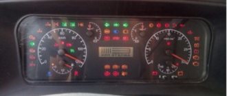
- The most common option is to integrate the sensor into the speedometer operating system. The functionality is simple: measuring the current speed, transmitting data. Therefore, when the driver says “the speedometer does not work,” most likely the situation develops directly around a faulty sensor that incorrectly transmits signals.
- The injection, ignition, and other engine systems may contain a speed limiter to adjust the operating system of the internal combustion engine. As the driving dynamics change, the load on the motor changes accordingly. More modern tractors are designed in such a way that the increased load is adjusted by the speed limit. In this way, a balance is achieved between the driving characteristics of the tractor and the power.
- Modern cars can include this unit in alarm systems or other security units. Such a move perfectly helps to adjust the speed of movement for the driver. A striking example is cruise control. Modern Kamaz models also have cruise controls and limiters so that the driver can fully concentrate on the road.
- The rarest case is power steering or other enhanced comfort systems. Hydraulics have a strong influence on determining speed, so sometimes determining mechanisms are installed in this particular unit. However, the hydraulic system is only part of the main mechanism that allows the car to better hold the road, that is, it is auxiliary.
In short, just one component, having one functionality, can serve as part of completely different systems. Each is important in its own way, but transmitting data to the speedometer still remains the most popular task, common on eighty percent of modern domestic Kamaz tractors. New foreign trucks operate on more advanced systems, however, packed with electronics, they require constant technical professional maintenance, while the owner of a domestic truck can largely service the tractor independently.
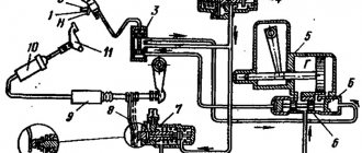
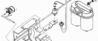
DSA - an abbreviation for vehicle speed sensor - being a traditional speedometer drive, it is simply mounted inside the transmission, transfer case or drive axle gearbox, monitoring the speed of the secondary or intermediate shaft. The next step in the process is to transfer the data to the speed measurement controller.
Operating principle of the speed sensor
Most sensors operate on the Hall effect. To determine speed and mileage, frequency pulses are used, which are sent at a certain interval. Impulses arise when the wheels rotate, so the mechanics calculate the data and they are displayed on transport devices. Typically, up to 6 thousand signals are issued for every kilometer. The KamAZ Euro speed sensor is considered the most advanced, since it was created on the basis of modern standards and European experience in the automotive sector, and is distinguished by its information content and accuracy.
Contact sensors
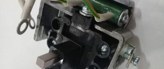
The basis of such devices is a corresponding microcircuit with a special plate and an amplification circuit. The chip and magnet do not move. To change the magnetic field and read pulses, rings with special slots rotate. The presence of small connectors allows you to read indicators for display on devices. The old-style KamAZ 5320 speed sensor was made using this principle.
However, on domestic models, including 4308, 53504 (the name appeared on some modifications after the restyling of 44108), the technical system has been improved. You can also read about Separating the pads on a KamAZ - Correct installation of the pads.
Non-contact sensors
The device operates on the Hall effect, but the design is different. On the shaft of the unit (gearbox or axle gearbox) there is a rotor or impulse disk with areas that are magnetized. There is a gap between the Hall chip and the rotor, but pulse signals are successfully read through standard connectors. This KamAZ speed sensor circuit is considered reliable, since spare parts interact less with each other and unwanted mechanical influence is prevented.
Angular velocity sensor (sensor)
4.8.3. Angular velocity sensor (sensor).
The wheel speed sensor is an electromagnetic type sensor. It consists of a coil wound around a magnet. The sensor is installed near the pulse ring, which is mounted on the car wheel hub. The pulse ring and speed sensor are shown in Figure 53, and the appearance of sensors from different manufacturers is shown in Figure 54.
Figure 53. Pulse ring with speed sensor
The structure of the sensor is shown in Figure 55. The sensor consists of a sensing element containing a permanent magnet and a winding. The sensor has a metal case, the end of the sensor is reinforced to protect it from abrasion of the metal case during operation. The sensor works with an impulse ring having 60, 80, 100 or 120 teeth. The speed sensor is mounted rigidly on a stationary part perpendicular to the impulse ring. The impulse ring is made of soft magnetic material, is rigidly mounted on the hub and rotates synchronously with the vehicle wheel. When the pulse ring rotates, the air gap between it and the sensitive element changes, which leads to a change in the magnetic flux and the appearance of alternating voltage in the winding. Since the frequency of the alternating voltage is proportional to the speed of rotation of the pulse ring, this allows you to determine the speed of rotation of the wheel. The sensor constantly monitors the changing speed of the vehicle.
Figure 54. Appearance of speed sensors and bushings
The output voltage of the sensor (Udd-Spitze-Spitze/Bepshina-Bepshina=l.6V) depends on the air gap between the speed sensor and the impulse ring and on the rotation speed of the impulse wheel.
From which it follows that with a minimum air gap and a maximum speed value, the voltage at the sensor output is maximum - Udd
The recommended distance between the teeth of the pulse ring and the end of the sensor is 0.8-1.4 mm; when this gap increases, the signal level of the sensors decreases below the permissible 0.1 V, which in turn will lead to a malfunction indication by the system - “large air distance between the speed sensor and an impulse ring."
The pulse ring rotating together with the wheel hub acts, by alternating the tooth-gap structure, on the magnetic flux of the inductive speed sensor and induces a sinusoidal voltage, the frequency of which is proportional to the number of revolutions of the wheel (the structure and principle of operation is shown in Figures 55...56). Approximate and reference graphs from the speed sensor are shown in Figure 57. In all this, it is not the voltage value that is processed, but the frequency and its change over time. This requires a certain minimum accuracy of the ring gear (parameters are shown in Figures 51 and 52).
Figure 55. Structure of the speed sensor
Attention: When various transitions in the magnetic flux, such as bolts, holes, grooves, stiffeners and much more, are located near the sensor, they affect the signal produced by the sensor. To eliminate such parasitic effects, the distance from the sensor to such a structural element must be more than 10 mm.
If this condition cannot be ensured, separate studies are required.
When the pulse ring rotates, the displacement of the teeth affects the sensor, that is, an EMF occurs, it sets an alternating voltage in the coil, the frequency of which is proportional to the speed of rotation of the wheel.
Figure 56. Operation of speed sensors
Figure 57. Graph of the signal coming from the speed sensor. Characteristics of speed sensors.
Table 10. Sensor parameters
| Parameter | Meaning | Unit change | |||
| Minimum | Average | Maximum | |||
| Wheel speed | 4,0 | 160 | km/h | ||
| Impulse per revolution | 60 | 100 | 180 | mV | |
| Sensitivity threshold | (f= 100 Hz) | 50 | 80 | 105 | mV |
| (f=800 Hz) | 65 | 140 | VPP | ||
| Input frequency range (signal frequency) | 10 | 900 | Hz | ||
| R average | 1,2 | 1,3-1,7 | 1,8 | kOhm | |
| U minimum (at 6 km/h), V | 0,9 | IN | |||
| Distance between the end of the sensor and the rim of the pulse ring, mm | 0,9 | 1,3 | mm | ||
Sensor installation tolerances.
The layout and installation of the speed sensor and pulse ring depends on the design of the axle used.
The impulse ring and speed sensor holder must be manufactured in such a way that they have the highest possible vibration resistance.
The permissible positional deviation of the sensor-ring when using a movable speed sensor is shown in Figures 58 and 59.
Attention: The above deviations also apply to the radial ring gear of the impulse ring (rotor).
Installation instructions.
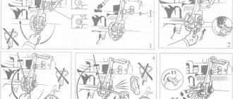
Correct installation of the sensor together with the bushing is ensured by inserting it into the impulse ring all the way (do not beat it!). Installation requirements are presented in Figures 58, 59, 60, 61, 62 and 63. Before installation, the sensor must be lubricated with a special paste, the types of pastes are given in Table 11. The paste protects the speed sensor components from
metal corrosion, promotes improved heat removal from the sensor, and allows the sensor to be dismantled even after long use without the use of great effort.
Figure 58. Installation tolerances
The distance between the middle axis of the speed sensor and the edge of the impulse ring is at least 2 mm.
When replacing the sensor, a new bushing must be installed. Before installation, the receiving drilled hole must be lubricated with a special lubricant.
Ensure that cable routing and fixing comply with regulations.
Figure 59. Installation tolerances
The angular deviation of the sensor axis from the perpendicular to the tooth plane is no more than 5° (0±5°).
If the cable of the angular velocity sensor breaks and cannot be replaced with a standard sensor, the wires must be connected by twisting the wires and then crimping them, as shown in Figure 89. It is unacceptable to connect the wires by soldering, due to a large drop in the signal level at the soldered junction.
Figure 60. Bushing - appearance
Figure 61: Sensor Installation
Designations: 1 — wheel hub, 2 — impulse ring, 3 — brake drum, 4 — bracket, 5 — brake shield, 6 — sealed gasket, 7 — caliper, 8 — speed sensor
Figure 62. Installing the sensor in the front axle wheel
Designations: 1 - wheel hub, 2 - impulse ring, 3 - sensor bushing, 4 - steering knuckle, 5 - ABS speed sensor, 6 - bracket
Figure 63. Installation of the sensor in the rear axle wheel
Table 11. Recommended Lubricants
| Manufacturer | Name | order number |
| "Wabco" | set of sensor (bushings and lubricant) | 830 502 578 0 441 032 921 2 830 502 579 0 441 032 922 2 |
| 5 g. Tube | 830 502 068 4 | |
| Staborags NBU 1 kg. | 830 502 063 4 | |
| "Knorr-Bremse" | 5 g. Tube Schmierfett | 190693 |
| NP RUE "Ekran" | VNII-NP-225 GOST 19782-74, or thread lubricant R-402 TU 301-04-020, or grease Penta-200 series (Penta-219D brand) TU 6-05-40245042-003P |
Possible malfunctions of the speed sensor
KamAZ 55102, 65115 often have device malfunctions, because such models have been produced for a long time and there are numerous used models on the domestic market. Malfunctions are manifested by problems with idle speed (the car may stall), corrosive changes in contacts.
The KamAZ gearbox and speed sensor must be replaced, otherwise the following problems may appear:
- lack of information about mileage and speed due to inoperative devices;
- malfunction of the engine (impaired idling speed, excessive fuel consumption, loss of power);
- serious problems with security systems.
Note! Be sure to use a sensor that was installed earlier or recommended by the car manufacturer. If the unit is incorrectly selected, it will not be possible to install it, switching between speeds will not occur correctly, or the technical data will not be read correctly.
Speedometers
Speedometer 87.3802010 or PA 8046-4P
Speedometer 81.3802010
Diameter 140mm, runs on 24 volt on-board network. It is mainly used on Kamaz or Maz trucks. There is a total and daily mileage counter and a speed limit alarm.
Speedometer 811.3802010
Diameter 140mm, runs on 12 volt on-board network. Suitable for GAZ, KAZ and PAZ.
Speedometer 85.3802010
Diameter 100mm, runs on 12 volt on-board network. Suitable for GAZ, UAZ and ZIL. Daily and total mileage counter. Very compact with a depth of only 7 centimeters.
You can buy these components from almost any supplier or at Avtopribor” in Vladimir.
tell me which sensor is suitable for the tachograph siemens vdo car maz 1999.
The KamAZ brake system is thought out to the smallest nuances, since the technical condition of the vehicle and the possibility of safe driving depend on it. The installed KamAZ speed sensor is an important device, as it allows you to monitor the technical performance of the vehicle.
Speedometer functions
The sensor is primarily connected to the speedometer. For this reason, you need not only to know where the KamAZ speed sensor is located, to carefully monitor its serviceability, but also to take into account the functionality:
- speed measurement and display;
- displaying information about the distance traveled;
- informing about the current time;
- alarm about exceeding the permissible speed;
- measurement of the number of pulses for correct reading of characteristics.
Speed sensors on KamAZ 43118 vehicles and other models must be operational for safe driving, both in the city and on the highways.
Speedometers and speed sensors for digital tachograph installation
Most of the vehicle fleet in our country is quite old and therefore, during the installation of tachographs, the speedometer and speed sensor very often have to be changed. This is done so that the tachograph “sees” the current speed of the car and can determine the distance traveled. If the car is old, then it usually has a mechanical speedometer on a cable, and in order to receive a pulse signal you have to install a speed sensor, and since the old tachograph is connected through a tachograph and must also have a pulse, we send the mechanical one to a landfill. The replacement process is quite labor-intensive and requires experience, which is needed both at the stage of calculating the cost of installation and at the stage of direct installation. In this article we will look at the main types of speedometers and speed sensors used during the installation process.