The question often arises among tractor drivers: “what oil to pour into the components and mechanisms of the MTZ tractor.” If you read the operating instructions, the old documents talk about using ordinary motor oil of the M-10, M-8 brands in the engine, which, however, is also used in parallel in hydraulics. Today, the manufacturer recommends modernly developed materials with improved characteristics that make it possible to extend the life of tractor units. This material deals with the brands of lubricants used for components and systems of the MTZ 82 tractor.
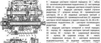
Design and diagram of the MTZ-82 front axle
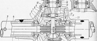
We will study this mechanism in full, but first we need to fully understand the circuit and devices of this mechanism. To do this, we present its complete diagram and give a breakdown of the details.
The main task of the front axle of the Belarus MTZ-82 tractor is to transmit torque from the engine to the steering front wheels. The mechanism itself consists of: transmission, front differential and wheel gearbox.
The transmission design is made of two bevel gears with spiral teeth. The drive gear (37) is placed on a tapered roller bearing (40) in the cup (39). The driven one (25) fits into the belt of the differential housing (27) and the splines, using a nut (24) it is secured against any axial movements.
Front drive axle differential
This mechanism uses a limited-slip self-locking differential. The cover (31) and the body (27) are connected by bolts; they contain semi-axial gears (21), a satellite (30, driven (36) and driving (28) friction discs. As well as pressure cups (35).
The differential integrally secures two axle shafts, eliminates separate wheel slipping and significantly increases the traction force of the tractor. When it is turned on, the wheels lock. Reinforcement from the axles passes to the satellites, which is transmitted by the shoulder cups (35). In turn, this causes the friction discs (26 and 36) to compress.
The differential is locked using friction.
If the friction force in the discs (26 and 28) exceeds the standard deviation at the moment of rotation, then slippage occurs. The MTZ-82 front axle differential is placed in the cover (20) and housing (34) on tapered roller bearings (32).
Additionally, a breather (33) is installed in the system, which maintains normal pressure in the differential cavity.
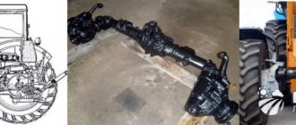
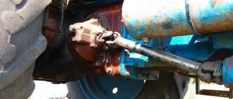
How is the front axle of a tractor connected?
With the help of hollow axles (58) and a beam, the bridge is connected, in turn, the hollow axles ensure the rolling of the front wheels and the bridge in the transverse plane. The axes are stopped from moving using bars (59).
Mechanical final drive gearboxes are installed in the sleeves of the cover (20) and the solid body (34). They consist of pairs of bevel gears, which serve as joints of equal angular velocities.
Splined shanks with gears secure the differential axle shaft and vertical shaft. The tractor axle shaft itself is mounted on two tapered roller bearings (14), and the vertical shaft rests on them and its installation takes place in the bore of the pivot pipe (13). The cuffs (16 and 45) together with the paronite gasket seal the cavity (19) along cover surface.
The pivot pipe (13) is supported by a coiled coil spring (49). The pipe itself fits into the sleeve (47); it is also pressed into the gear housing (53) and secured with a pin.
How is torque transmitted?
The process itself is quite simple to understand; first, the disc flange (2) rotates on a roller-type bearing (50) and a pair of conical bearings (4), which are pressed into a glass (6), which is located in the bore of the cover (1).
The gear (52) and bearing are secured with two bolts and a washer from moving along the axis. The lower conical pair is sealed using a rubber ring, which is placed in the glass (6), as well as a lip and paronite gasket along the plane of the housing cover (53). A swing arm with trapezoid steering rods and a bracket for the wheel fenders is attached to the gear housing. Torque is transmitted to the disc flange (2) from the differential axle gear (21), using the gear of the lower and upper bevel pair.
Repair of the front drive axle MTZ-82
We will consider the repair in several stages depending on those symptoms. Which can be observed. Each stage will be illustrated with detailed pictures.
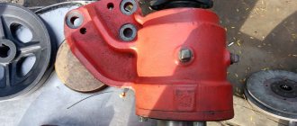
If traces of grease appear on the propeller shaft flange and the main gear housing, this is the first sign that elasticity will be lost and the main gear cuff will collapse. To do this, replace the cuffs and disconnect the driveshaft. First, unscrew the castle nut and remove the cardan flange. Next, unscrew the bolts securing the main gear cup bearings and two mounting bolts. Afterwards, the drive gear is pressed into the glass and the assembly with the cuff itself is removed.
If traces of oil are found on the inner surface of the wheel rim or on the disk flange, this is a sign that the wheel axle is damaged. To do this, you need to remove the wheel and the final drive gearbox as a complete assembly (see the diagram of the arrangement of parts for the final drive gearbox of the MTZ-82 tractor).
then you need to unscrew the two radial bearing securing bolts and remove the driven gear.
So we looked at the main problems of the front axle of the MTZ-82 tractor. We hope that this article was useful to you.
Commentaires • 85
Pressing out the rear axle axle shaft from the sleeve 1 - axle shaft; 2 — axle sleeve; 3 — puller Fig. The support for the lower end of the spring is the bearing located in the gearbox housing 53. If necessary, adjustments are made to eliminate the increased gaps. Removing the brake discs of the MTZ differential locking mechanism. The inoperability of the MTZ differential locking mechanism can be caused by a diaphragm rupture, wear of the friction clutch discs and the locking shaft. The relative position of the parts of the differential locking mechanism 1 - cover; 2 — diaphragm cover; 3 - diaphragm; 4 - gasket; 5 — pressure disk; 6 — locking shaft; 7 — squeezing disk; 8 — disk; 9 — intermediate disk; 10 — locking clutch housing; 11 — casing Axle shafts of the MTZ tractor Traces of grease on the inner rim of the wheel or on the cover of the axle shaft sleeve indicate destruction or loss of elasticity of the axle shaft cuff. Set d—60 mm; special instruction. Install the steering linkage with grease nipples backwards along the tractor. Disassembly is carried out in the following sequence: Place the car on a level surface and secure it with wheel chocks. Photo to attract attention. We hope that this article was useful to you.
If they move on the splines, then the nut needs to be tightened. Unscrew the front wheel cover mounting bolts, remove the cover and gasket from the front wheel hub. Maintenance of the wheel gear In order not to bring the wheel gear to a state where it needs major repairs, the structure must be constantly maintained. In addition to the oil seal itself, transmission oil will be needed to replenish the lost amount in the gearbox. If the frictional force in disks 26, 28 is exceeded when the front axle is engaged while turning the MTZ 82 tractor, they slip.
There is no forty lighter and more economical than MTZ. The axles are stopped from moving using bars. If the friction force in disks 26, 28 is exceeded when the front axle is engaged, when turning the MTZ 82 tractor, they slip.
Front axle MTZ-82: diagram, device, adjustment, repair
If you find grease stains on the driveshaft flange and final drive housing, keep in mind that these marks indicate loss of elasticity or failure of the drive gear cuff.
How to replace the cuff? To replace the cuff of the main gear drive gear, you need to disconnect the driveshaft, unscrew the castle nut and remove the driveshaft flange. After this, unscrew the bolts securing the main gear bearing cup, and then use two mounting bolts to squeeze it out of the axle housing. Then the drive gear is pushed out of the cup and the cage assembly with the cuff is removed (Fig. 2.4.20—2.4.22).
Rice. 2.4.20. The relative arrangement of the parts of the main gear of the drive axle of the MTZ-82 tractor: 1 - drive gear; 2, 5 — bearings; 3 — adjusting shims; 4 - glass; 6 - cuff; 7 — oil seal cage; 8 - flange; 9 - nut
Rice. 2.4.21. How to press out the oil seal race assembly with the cuff of the MTZ tractor: 1 - oil seal race; 2 - glass; 3 - two-jaw puller
Rice. 2.4.22. Pressing the inner race of the bearing from the drive gear of the MTZ tractor: 1 - bearing; 2 - drive gear; 3 - two-jaw puller
An oil leak on the inside of the wheel rim or disk flange indicates destruction of the wheel axle seals.
To get to the cuff cup, first remove the wheel and final drive gear assembly (see Fig. 2.4.23, 2.4.24). Next, unscrew the two radial bearing mounting bolts, pull out the driven gear and press out the wheel flange (Fig. 2.4.25, 2.4.26). The cup of the cuffs and the cup of the outer race of the bearing can be pressed out using two mounting bolts (Fig. 2.4.27, 2.4.28).
Rice. 2.4.24. The relative arrangement of the parts of the final drive gearbox of the MTZ tractor: 1— flange; 2 - mud trap; 3 — oil seal body; 4—cuff; 5, 9, 13, 17, 20, 27, 29, 36 — bearings; 6, 23, 31, 38, 40 — gaskets; 7 - glass; 8, 32 — rings; 10, 26 — shims; 11. 22, 39 — covers; 12, 37 — gears; 14 — washer; 15 - plastane; 16 - nut; 18 - shaft; 19 — axle shaft; 21 — adjusting ring; 24, 34 — hulls; 25 - cuff; 28 — spring; 30 — kingpin pipe; 33 — lever; 35 pin; 41 - sleeve
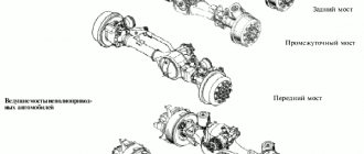
Rear axle design MTZ 82(80): diagram, repair, adjustments
The MTZ 80(82) rear axle mechanism, enclosed in a cast iron body, is the most massive part of the tractor transmission. In addition to housing the mechanism, the crankcase serves as the frame of the tractor. The internal cavity is divided by partitions to strengthen the body and accommodate the rotation supports of the mechanisms. Access is through the top hatch, closed with a sheet metal cover. The upper plane of the body is the basis for attaching the tractor cab; brackets for mounting the rear linkage are attached to the rear part of the body; axle shaft sleeves are located on the sides. The planetary gearbox of the rear PTO is located in the rear part of the unit housing.
In tractors MTZ 50(52) and MTZ 80(82), the rear axle assembly is absolutely interchangeable.
Design and principle of operation of the bridge
The bridge has a kinematic diagram with internal final drives. All gearbox parts operate in a common oil bath, are lubricated by splashing, and are combined with the gearbox and intermediate part of the transmission into a single lubrication system. Oil is poured through the plug in the upper gearbox cover to the level of the lower edge of the inspection hole. The total volume of transmission oil filling is 40 liters.
main gear
The gearbox mechanism receives longitudinal rotation from the secondary shaft of the gearbox attached to the front wall of the rear axle housing. The transmission is carried out through a bevel pair of gears with helical teeth. In the bridge design, this gear pair is called the main gear. The gears take the rotation ratio created by the gearbox and convert longitudinal rotation into transverse rotation. The drive gear is placed on the splines of the shank of the secondary shaft of the box and is tightened with a cotter nut. The main drive driven gear is attached to the differential housing with bolts and nuts with locking folding plates.
Differential
The mechanism carries out the function of distributing torque to the drive wheels when the tractor turns, providing different angular speeds of rotation of the drive wheels.
The device is a closed planetary mechanism in a cylindrical housing, consisting of two parts tightened with bolts. Inside the assembly there is a crosspiece, sandwiched by two halves of a housing with four satellites in the form of straight-cut bevel gears rotating on bronze bushings. Thrust steel washers are installed between the satellite body and the axis. The satellites interact with the left and right semi-axial bevel gears, which transmit rotation to the corresponding sides to the drive gears of the final drive of the bridge. Bronze thrust washers are installed between the semi-axial gears and the housing. The gears in the housing cups rotate on tapered roller bearings.
Operating modes
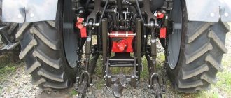
On an ongoing basis, on dirt roads in rural areas, they use the automatic mode of operation of the front axle. To reduce the wear of assembly parts in field work conditions as part of land-cultivating units - plowing, cultivation, it is advisable to use the forced operating mode of the FDA. In conditions of constant driving on roads with hard, dry surfaces, it is recommended to disable the front axle drive.
Front axle control
The control lever is located on the right side of the driver's seat and is connected to a rod passing through the cabin floor. The control handle has three positions:
- medium - automatic mode is enabled
- lower - front axle is turned off
- upper — FDA is engaged in forced mode
In later versions of the tractor, control is carried out by a lever, in older versions by changing the position of the handle.
New model FDA drive control
Old style FDA activation mechanism
Automatic switching on
In automatic mode, the transfer case transmits rotation only when slipping of the rear drive wheels occurs. In this case, by selecting the position of the control lever, the block sliding along the shaft splines engages its smaller ring gear only with the driven race of the overrunning clutch. This ensures that both parts of the overrunning clutch rotate independently in the unlocked position. The power transmission is switched on due to the jamming of the rollers in the grooves and the connection of both cages when the speed of rotation of the driven cage of the mechanism slows down relative to the speed of the constantly rotating driving part of the transfer case clutch.
Node operating modes
The gear ratios of the mechanism are designed so that the driven race of the roller clutch, receiving rotation from the passive rolling of the front wheels of the tractor, rotates 6% faster than the driving race of the mechanism. Thus, during standard tractor movement, the clutch does not engage and torque is not transmitted to the front axle from the gearbox. When the movement of the front wheels naturally slows down as a result of slipping of the rear drive wheels, the rotation speed transmitted to the driven race of the overrunning mechanism decreases, but the speed of the drive gear remains unchanged. At the moment the rotation speeds of both parts of the mechanism are equalized, the rollers enter the wedge grooves, causing the parts to rotate as one whole. From the moment of actuation, power is transferred to the wheels of the front axle of the tractor until the rear wheels stop slipping. When the rotation speed of the driven cage increases due to the reverse rotation received from the front wheels, the rollers will come out of the grooves and the clutch will automatically disengage.
Forced mode
It is activated by introducing the engagement of the toothed sliding block with both the inner gear rims of the outer drive and inner driven races of the overrunning clutch. By connecting the three parts of the mechanism, a single rigid block is formed, which receives rotation from the intermediate gear in the gearbox with subsequent transmission through the flanged shank of the transfer shaft to the FDA cardan drive. This inclusion ensures constant power transfer to the front axle.
Disabling FDA
When selecting a position where the gear block disengages from both rims of the two parts of the overrunning clutch, the FDA drive is completely disconnected. In this case, the driving and driven parts of the overrunning mechanism and the gear block rotate independently of each other, that is, the automatic and forced modes are disabled.
Repair and adjustment of the rear axle MTZ 80
The rear axle of the Belarus tractor has a fairly reliable design; with proper care, the unit can be operated without major repairs for decades. The main causes of problems are: systematic overloading of the unit with slipping, frequent use of locking under load, lack of sufficient lubrication. The appearance of unacceptable gaps: in the meshing of gears, in the seats in the axes of rotation of shafts and gears when bearings are worn, in splined joints leads to the appearance of unacceptable vibration during the rotation of parts. As a result, runout occurs, leading to coloring of the gear wheel teeth, rapid breaking and wear of the seats, followed by jamming and complete failure of the mechanism. It is recommended to stop operating the tractor if noise, hum or rattle occurs.
When deciding to stop a tractor for repairs, they are usually guided by the principle: “The sooner a problem in the operation of the mechanism is detected and eliminated, the less expensive it will be to repair the unit.”
To gain direct access to the mechanism when diagnosing and repairing the unit, it is necessary to completely dismantle the tractor cabin, fuel tanks, power hydraulic cylinder of the linkage and open the top cover of the axle gearbox and gearbox, as well as drain the oil from the transmission housing. Visual inspection reveals the degree of wear of the mechanism parts. By rotating the gears, inspect the condition of the teeth; using a mandrel (mount), check for the presence of shackles on the axles and rotation supports, in the seats of the mechanism parts, and in the meshing of gears and splined joints. Based on the fact of detected problems, a decision is made to dismantle parts or components of the mechanism for final detailed troubleshooting and subsequent replacement of parts.
Installing the drive final drive gear
The correct installation of a helical bevel gear on the shank of the secondary shaft of the gearbox consists of three aspects: the optimal clearance in the shaft bearing races must be taken into account, the output of the drive gear on the shank must be within specified limits, and tightening the gear with a nut must ensure the integrity of the secondary shaft structure without axial clearances. When installing the drive gear on the shank, tighten the locking nut as much as possible. This eliminates all axial gaps in the connection of the secondary shaft parts. The glass compresses the bearing races.
Sufficient clearance in the bearing is checked by the rotational force applied to the gear, made integral with the secondary shaft without taking into account the engagement of the bevel pair. The force should not exceed 6-7 N.m or 0.6-0.7 kgf. The tension in the bearing races is loosened by placing pairs of adjusting plates with a thickness of 0.2 and 0.5 mm under the bearing cup.
Bolts are screwed into the pressing holes of the cup flange, which, when tightened, rest against the gearbox housing and move the cup away, loosening the tension in the cages. Having achieved sufficient clearance, install plates of appropriate thickness and tighten the glass flange with standard bolts.
The clearance in the bearings of the secondary shaft of the box should not exceed 0.3 mm. During assembly, it is necessary to take into account that the distance from the outer end plane of the gear to the outer plane of the gearbox housing must correspond to 58 ± 0.15 mm. Insufficient output is increased by placing washers under the gear.
Adjusting the main pair of MTZ 80 rear axle
When installing the engagement in a pair of final drive gears, two aspects are taken into account: sufficient clearance in the engagement, the correct contact patch in the teeth of the pair.
To obtain normal engagement and optimal contact patch of the gear teeth, they must be installed so that the cones that form them coincide. Adjustment of the lateral clearance in the engagement is adjusted by selecting and installing adjusting plates between the flanges of the cups of the drive shafts of the final drives and the axle housing, as for setting the clearance in the differential bearings.
In a new conical pair installed, the engagement gap should be between 0.25 and 0.55 mm. The check is carried out with an indicator at three equidistant points of contact between the gears. You can also check the gap with a piece of folded newspaper paper, considering that the thickness of the newspaper sheet is 0.1 mm. The gap is determined empirically, taking into account the number of layers at which the teeth begin to cut through the layers of paper.
Correct adjustment is carried out only after adjusting the bearings of the secondary shaft of the gearbox. During normal operation of the main gear with the working, a gap of up to 2 mm is allowed. Reducing the gap in this case is unacceptable, since the established working contact of the gears is disrupted, which can lead to jamming of the pair. To determine the contact patch, apply paint to several teeth of the driven gear and turn the drive gear in one direction or the other. The paint imprint on the teeth will indicate the nature of the contact.
A normal impression occupies 50% of the working surface of the tooth and is slightly shifted towards the narrow end of the tooth. If the contact is incorrect, the position of the drive or driven gear must be changed. A pair of gears is not dismantled; when a gear fails, the pair is replaced. Adjustment of the lateral clearance in engagement and adjustment of the contact patch is carried out only when installing a new pair, and is not adjusted during operation.
Adjusting the differential bearings
Scheduled adjustment of bearings is carried out every 3000 hours of operation approximately every two seasons. An increase in the gap as a result of wear of the teeth and the bearings themselves to 0.3 mm leads to runout and vibration in the mechanism. Signs of a problem are usually the appearance of hum and noise during operation. The adjustment is carried out by selecting adjusting shims with a thickness of 0.2 and 0.5 mm for the flange of the glass of the left drive shaft of the final drive.
The gap is checked with an indicator, bringing it to the driven gear. Swinging the mandrel with a force of 50-60 kgf. in the axial direction. The optimal clearance in the bearings should be 0.05 mm, and an interference of no more than 0.1 mm is also allowed. The permissible moment of resistance during rotation of the differential, applied to the outer ends of the teeth of the driven gear, should be no more than 30-50 N.m or 3-5 kgf.
Since the driven gear is pressed against the right bearing, in order not to disturb the clearance in the meshing of the main gear gears, the adjustment is made by selecting shims on the left side. To do this, disconnect the left brake drive rods and the oil line of the automatic locking hydraulic drive. Then dismantle the automatic locking mechanism with the locking shaft and the working drum of the left brake. Loosen the bolts securing the left glass and press it off, screwing the bolts into the dismantling holes in the flange. Thus, gaining access to the adjustment plates. After installing the desired plate package, tighten the flange, turning the differential so that the bearing rollers are in the correct place.
Oil for hydraulics and power steering or power steering
For oils used in hydraulics , it is important to maintain a viscosity acceptable for normal operation of hydraulic units under conditions of minimum and maximum temperatures. Thus, completely frozen oil, when the temperature drops, may not be pumped by the pump and block the operation of the hydraulics, and create unacceptable loads in certain parts of the system. The loss of viscosity by the oil when heated will reduce the efficiency of the system's hydraulic power units as a result of a rapid drop in pressure.
| GNS tank (volume 20 liters with power steering or 25 liters with power steering) with hydraulic units | Basics | Summer - M-10G2, M-10G2K, Winter - M-8G2K |
| Duplicate | All-season hydraulic: BECHEM Stariol No. 32, No. 68; ADDINOL Hydraulikol HLP 32, HLP 68; TNK Gidravlik HLP 32, HLP 68; HYDROL HLP 32, HLP 68; WHITTOL HLP 32; Lukoil Geyser 32ST, 68ST; Hydraulic HLP 32, HLP 68. | |
| Reserve | In summer Industrial oil IGP-30, In winter IGP-18 | |
| Separate filling of the power steering housing (6 liters) | Basics | Summer - M-10G2, M-10G2K, Winter - M-8G2K |
| Duplicate | In summer Industrial oil IGP-30, In winter IGP-18 | |
| Reserve | All-season hydraulic: BECHEM Stariol No. 32, No. 68; ADDINOL Hydraulikol HLP 32, HLP 68; TNK Gidravlik HLP 32, HLP 68; HYDROL HLP 32, HLP 68; WHITTOL HLP 32; Lukoil Geyser 32ST, 68ST; Hydraulic HLP 32, HLP 68. |
The hydraulic fluid is replaced during seasonal maintenance of the tractor.