For comfortable and efficient driving, the steering mechanism of the MTZ 80(82) tractor is equipped with power steering. The unit performs the function of transmitting rotation from the steering wheel to the steering bipod while simultaneously easing the effort when turning and mitigating reverse vibration when driving on roads with uneven surfaces. Strengthening is achieved by fluid pressure acting on the working parts of the mechanism.
Power steering MTZ 80
The unit was installed on earlier MTZ-80(82) models and is not inferior in its functional and performance qualities to the later installed hydrostatic power steering system - GORU.
Design and principle of operation
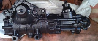
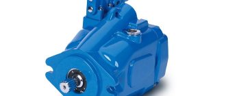
The cast iron housing of the MTZ 80 (82) power steering is located on the front frame beam between the front front wall of the hood and the diesel engine cooling radiator of the machine. The unit is a mechanism with a worm gearbox, equipped with an autonomous hydraulic system with a spool for controlling the flow of working fluid, a left-hand rotation gear hydraulic pump NSh-10-L-U GOST 8753-71, a double-acting power cylinder and a safety valve. The system's hydraulic pump is driven by the engine timing gear.
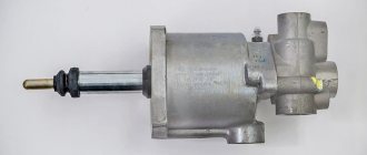
Power steering device
A worm is installed in the amplifier body, connected by turns to the sector and its end part to the valve spool of the assembly. At the ends of the spool there are thrust bearings, into which the plungers rest under the pressure of the springs. At the same time, the outer sides of the plungers rest against the housing parts of the distributor. Plungers and springs hold the spool in the neutral position through bearings. When the steering wheel rotates, the worm begins to move the sector in turns, turning the bipod shaft. The resulting resistance of the wheels is transmitted through the mechanism to the worm, forming a force that moves it axially forward or backward depending on the direction of rotation. By its displacement, the worm interacts with the valve spool of the assembly, moving it relative to the axis. Thus, the spool controls the flow of oil under pressure. When moving straight, the distributor spool, spring-loaded, is in the neutral position, the pressure supplied by the pump is released into the amplifier housing, which is the hydraulic tank of the system.
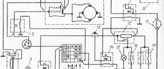
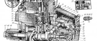
Diagram of operation of the distributor when turning right and left
By rotating the steering wheel, the worm moves the spool, which opens the lines of the cavities of the power cylinder with its belts. Moreover, depending on the direction of rotation, one cavity is connected to a line supplying oil under pressure, the other to a drain. The spool drops pressure into the cylinder cavity only during direct rotation of the steering wheel. When the steering wheel stops, the worm stops acting on the distributor spool, which, under the force of the springs, takes a neutral position, dumping oil into the drain cavity.
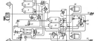
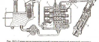
MTZ power steering diagram
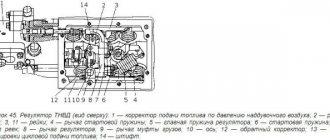
The piston of the cylinder 25 interacts through a rod with a rack 14 connected to sector 12 . When the spool supplies pressure to one of the cavities, the rod transmits force to the rack moving the sector, facilitating the rotation of the shaft 28 connected to the bipod 13 . The working pressure in the hydraulic system is 2-4 MPa. By turning the steering wheel to the maximum angle of rotation, the pressure reaches its maximum value of 8 mPa and is limited by safety valve 7 .
The driver’s feeling of “Road Feeling” of resistance to turning during steering is provided by the pressure from the discharge channel in the cavities with springs acting on the plunger. When controlled without force, the worm does not interact with the spool and the hydraulic system does not participate in the amplification.
Additionally, the unit is equipped with a differential automatic locking sensor located in the rack stop. The device includes a spool 21 , a rotary valve 18 with a flywheel, a pusher and a probe 20 . An unregulated pressure reducing valve maintains a pressure of 0.7-0.9 MPa in the locking hydraulic system. The device provides differential locking when driving straight and automatically turns it off when the wheels are turned more than 8 ̊.
Modernization (how to remake) the MTZ steering column under the cylinder
Installation of a hydraulic cylinder and a metering pump on the steering control of a MTZ tractor (old drive axle)More details
Modernization (power steering) of the steering wheel on MTZ 80More details
I answer the question! How I made a cylinder for the steering MTZ-80. Read more
Repair and refurbishment from gura - for MTZ 80 dispenser and a little history from family life. Read more
How to convert MTZ-50-80 to a dispenser pump. Read more
MTZ steering control AlterationRead more
Modernization of the steering column MTZ 80More details
Conversion of MTZ 80 from a steering column to a dispenser pump. Read more
Modernization of steering wheel MTZ 80 Gur per cylinderRead more
MTZ-82 conversion of steering wheel to dispenser 2More details
Source
Adjustments
The node is configured in good condition. Its correctness is an important factor in the efficient operation of the amplifier and preservation of its service life. The adjustment is divided into adjusting the gearing gaps of mechanical pairs and the spool stroke.
Worm-sector engagement
The adjustment is made when the steering rods and steering joints are in good condition; the free play of the steering wheel should not exceed 30 ̊ with the engine running.
Setup procedure:
- The front axle of the tractor is jacked up or the bipod is disconnected from the steering rods.
- Loosen the bolt of the adjusting eccentric sleeve.
- Turn the bushing clockwise until the worm stops in maximum engagement with the sector.
- With the engine running, turn the steering wheel to determine the engagement position without feeling stuck, increasing the gap by turning the bushing counterclockwise.
- Tighten the bushing mounting bolt, remove the bridge from the jack or connect the bipod to the steering rods.
Tightening the worm spherical nut
Tightening the nut eliminates the gap between the spool and the bearing races, formed as a result of wear or weakening. The appearance of a gap is reflected in an increase in the free play of the steering wheel and the appearance of the effect of dangling steering wheels. When play appears, the spool can arbitrarily connect the cylinder cavities to the oil pressure lines.
Worm Ball Nut Tightening
- Unscrew the bolts securing the distributor to the amplifier body.
- Remove the cover and attach the distributor to two diagonally placed bolts 5 . The thickness of the cover flange is compensated by backing washers 4 or large diameter nuts under the bolt heads.
- Then unscrew the adjusting nut 1 and tighten it until the spool stops in the bearing races. Tightening is carried out with a force of 20 Nm.
- By unscrewing the spherical nut until the hole on the worm shaft first matches, the nut is secured with a cotter pin.
- Dismantle the installation bolts with washers and install the cover with the gasket, tightening with four bolts as usual.
Correct tightening ensures that the spool fits snugly against the bearing races and ensures that the spool returns to the neutral position under the action of the springs when the steering wheel stops rotating. Excessive tightening increases the force on the steering wheel and leads to rapid wear of the distributor thrust bearings.
Adjusting the sector-rack engagement
The gap in the sector-rack engagement of the cylinder piston rod is regulated by the number of spacers between the amplifier body and the rack stop. A sufficient gap of 0.25-0.3 mm ensures the pair operates without jamming.
Installing shims Rack and stop clearance
Spool stroke uniformity
The spool stroke is controlled by shims between the amplifier body and the distributor, the distributor and the spherical nut cover. If the rotation to the left is insufficient, an additional gasket of 0.5-1 mm is installed between the column body and the distributor; if the rotation to the right is insufficient, a gasket is installed under the spherical nut cover. Thus, the amplitude of the spool stroke from left to right is equalized.
System pressure
The pressure of safety valve 7 is adjusted by changing the spring compression. By tightening the valve screw, the compression of the spring increases and, accordingly, the maximum operating pressure of the amplifier hydraulic system.
Related Posts
MTZ 82. The steering was converted to a dispenser and cylinder. Why is the steering wheel still hard to turn? When you press on the gas it gets better. What is the reason?
The opinion of experts is interesting. Such a problem: an old MTZ 82, we decided to remake the steering with a dispenser and a cylinder, we redid everything, the steering wheel still turns tightly, you press the gas, the situation changes for the better, but as soon as you release the gas, the steering stops working again. We thought the old NSh 10 could not cope, we bought a new NSh 16, replaced it, the situation did not change, we came to the store to change the dispenser, the store said that they had encountered such problems and most likely the problem was in the cylinder. We bought it, replaced it, the situation has not changed again, the oil in the M8DM system does not foam, but in the hydraulic tank during operation it gushes, bubbles and gets very hot, please tell me what the problem might be, don’t ignore it.
On 82 there is a winch on the rear linkage. Why does the thread on the top two of the five bolts securing the hitch to the bridge break off during operation?
Greetings guys. Such a problem; 82 has a winch on the rear linkage. In the process of work, it breaks the threads on the top two bolts out of five securing the hitch to the bridge. What do you advise?
How to convert the steering to fit the MTZ-82 dispenser? How did you attach the bracket for the cylinder on the old-style bridge?
hello everyone Maybe someone remade the steering for the MTZ-82 dispenser, who how to attach the bracket for the cylinder on the old-style bridge?
There is a problem with the steering of the Mtz 82. Why does it jam when working with the kun, when lifting a load, and the steering wheel does not turn? Old style bridge.
Good day) there is a problem with the steering of the MTZ 82. I am working with a kun, and when lifting a load it jams. The steering wheel, if you lift anything heavy, generally jams and until you make a movement, it does not turn. Without a load everything is fine. What could it be? The bridge is an old model, installed on the mountain.
How to remove the pins of the middle axle of the front axle MTZ 82? I pull with the puller - it doesn’t work.
Good afternoon. I can’t pull out the fingers of the middle axle of the front axle of the Mtz 82, I’m pulling with a puller, it doesn’t work, maybe someone else did something, for example, warmed it up or hit it somewhere. Tell me, who has encountered this?
How to connect a dispenser with a gur on MTZ82? What nuances might there be?
Are there those who were friends with the dispenser and the gur on MTZ82? What nuances might there be?
I converted the steering on MTZ 82 to a dispenser. Why do original steering hydraulic cylinders leak? Already changed 4 pieces.
Guys, please tell me, I changed the steering on the MTZ 82 to a dispenser, I’ve already changed 4 original steering hydraulic cylinders, they’re all leaking guys, please tell me what could be the problem?
MTZ tractor with beam bridge. What kind of gearbox does it have, with or without synchronizers, like in a regular MTZ82?
Hello, I have a question: the MTZ tractor with a beam axle, produced in 2019, what kind of gearbox does it have, with or without synchronizers like in a regular MTZ82? Thank you in advance
Will the front axle from MTZ 82 fit on MTZ 50?
Question from a subscriber: Hello everyone. Tell me, will the front axle from MTZ 82 fit on the MTZ 50?
Is it possible to convert MTZ 80 to 82? Are there any disadvantages?
Hello guys, I have a question. Has anyone converted MTZ 80 to 82, were there any disadvantages there?
Source
Installing a dispenser on an old-style MTZ 82
The main difficulties when installing the dispenser on tractors of the earliest production MTZ 82 (80) is fastening the bracket for the hydraulic cylinder to the bridge beam in the absence of installation space. The network shows the experience of practitioners from several options for solving this problem using clamps on the beam or direct welding of the bracket.
The most acceptable solution that ensures a reliable connection is the following technology, which is feasible under normal plumbing conditions:
- A place is marked for a platform for attaching the bracket to a beam of the appropriate size for the contact plane of the part. The measurement is carried out by applying a hydraulic cylinder with the rod extended to the middle position (100 mm), provided that the edge of the rod is connected to the rotary lever in the straight position of the wheels and the symmetrical reach of the left and right axle axles of the bridge relative to the axis of movement of the tractor. In this case, the location for the connection area between the bracket and the bridge is determined by the coincidence of the eye of the second edge of the hydraulic cylinder with the hole of the bracket. The matching hole must match the installed bridge track. It should be taken into account that, in the case of a minimum track set, the cylinder is connected to the rightmost hole of the bracket (along the path of the tractor), with a maximum track to the far left.
- Having determined the location of the platform by attaching the cylinder and bracket to the bridge beam, they begin to prepare it. To ensure the connection of a flat part, it is necessary to bring the semicircular surface of the bridge beam as close as possible to the flat one by surfacing the metal with electric arc welding and subsequent surface treatment with a grinder grinder wheel.
- After obtaining a more or less flat surface, prepare a tire from a sheet of steel with a thickness of 15 -20 mm corresponding to the contact area of the bracket of the size. The holes on the tire are marked and drilled using the holes in the bracket. Cut the appropriate threads for the four bracket mounting bolts and adjust the diameter of the two threadless holes for the pins.
- At the final stage, the manufactured part is applied to the prepared welded area on the bridge beam and welded with a seam along the perimeter with maximum observance of the level of the horizontal position of the tire plane. Thus, a flat platform will be created for a tight fit and reliable connection of the bracket to the bridge without the use of milling.
Source
Unit repair
There are several possible scenarios for repairing the power steering unit. They depend on the type of breakdown or malfunction that occurs.
Oil leak and depressurization
The first criterion demonstrating the presence of a malfunction in the unit is the lack of tightness of the hydraulic system seals. The tightness ensures the safety of the operating pressure during operation of the unit, and also prevents changes in the magnitude of the force that acts on the amplifier organs.
If an oil leak is detected in the power steering, the following is replaced:
The proper functioning of the connection of the assembly parts ensures the normal operation of the structure, preventing jamming or breakage.
Changing the working stroke
The standard spool stroke, if we consider the classic movement of the part in one direction, is 1.2 mm. This is enough to completely open the channels for the inlet and outlet of working fluid. If the stroke is disrupted and the structure deviates in any direction, the distributor ceases to cope with its function.
The result of the malfunction is the lack of a sufficient amount of working fluid in the cavity, which makes it impossible to create the required amount of hydraulic gain.
One of the reasons for such a malfunction is unacceptable backlash that occurs when assembly units are connected poorly. In total, these backlashes negatively affect the movement of the spool along the axis. Therefore, it is important to keep track of:
If the backlash is adjusted incorrectly and the indicators are allowed to change, the design of the unit will quickly wear out, which will lead to breakage of the teeth, coils, and worm. If parts fail, they should be replaced with new elements.
Increasing the distance between parts
During operation, gaps between individual elements that do not require tightness may increase. Tractor drivers recommend using two methods for leveling the resulting gaps:
Both methods are in demand in practice, but they are not capable of completely repairing the unit if they are installed incorrectly and all conditions for their reliable operation are not provided. If incorrectly adjusted, enlarged elements will quickly wear out and lead to power steering failure.