Design and operation of an electric torch heater
TO
category:
Kamaz Ural cars
—
Design and operation of an electric torch heater
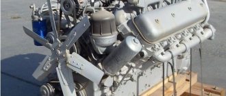
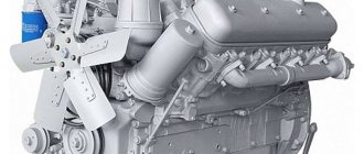
The principle of operation of an electric torch heater is based on heating the air entering the cylinders with a flame formed in the intake pipes during the evaporation and combustion of diesel fuel vapors during the engine cranking period. Model 740 engines of KamAZ-5320, KamAZ-4310 and Ural-4320 vehicles use an electric torch heater of a similar design.
Rice. 2.29. Electric torch candle: 1 - heating element; 2 — heating element casing; 3 - body; 4 - fuel filter; 5 — fuel jet; 6 - tube; 7 - mesh; 8 - nut; 9 - volumetric mesh; 10 - screen
—
The electrical system of the electric torch heater includes two electric torch plugs, an electromagnetic fuel valve, a thermal relay resistor, a relay for turning on the electric torch plugs, a relay for turning on the generator excitation winding, a control lamp and a power button.
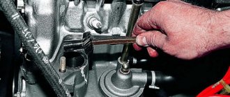
Electric torch spark plugs are screwed into the threaded holes of the engine intake manifolds and connected to the low-pressure line of the fuel supply system in the section between the fine fuel filter and the high-pressure fuel pump. Fuel is supplied to the spark plugs when the engine is started by a low-pressure pump through a fine filter, while the bypass valve of the high-pressure fuel pump and the nozzle valve of the fine fuel filter close the drain fuel lines and ensure the supply of fuel under pressure to the spark plugs with minimal delay time from the opening of the solenoid valve.
In the case (Fig. 2.
29) an electric heating element is placed, which is a metal casing, inside of which a spiral is pressed into a special filler that has good thermal conductivity and provides electrical insulation of the spiral from the casing. The fuel coming from the power system passes through the filter and nozzle into the heating cavity, where it is heated and evaporated. To obtain a large evaporation surface in a small volume, grids are provided. A screen with two rows of holes for the passage of air prevents the flame from stalling and attenuation when the speed of air movement in the intake pipes increases due to high starter cranking speeds or after starting the engine.
Solenoid fuel valve (Fig. 2.
30) ensures that the fuel supply to the flare plugs is turned on (when the valve is opened, driven by the solenoid coil) and turned off (when the valve is closed by the spring after the voltage is removed from the coil) in accordance with the control circuit. It is installed on the engine.
Rice. 2.30.
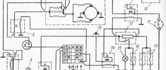
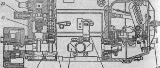
Electrical circuit of the starting device: 1— switch for instruments and starter; 2 - relay for turning on and blocking the ground switch; 3 — ground switch button; 4 — “mass” switch; 5 — starter activation relay; 6 — batteries; 7 - backup switch start:ra; 8 — starter; 9 — relay for switching on the generator excitation winding; 10 - voltage regulator; 11 — generator excitation winding; 12 — thermal relay; 13 — starter switch; 14 — relay for switching on spark plugs for maximum heating; 15 — control lamp; 16 — electromagnetic fuel valve; 17 — electric torch candle
A resistor with a thermal relay and additional resistance ensures that the electric torch heater is ready for operation by timely activation of the electromagnetic fuel valve and pre-heating of the heating elements of the torch plugs.
The resistor is an open heating coil; The thermal relay is made in the form of contacts made of a bimetallic plate, which close as it warms up. A resistor with a thermal relay and an additional resistance are installed on the cabin panel.
The operation of the electric torch heater is ensured by a special electrical circuit of the starting device (Fig. 2.
30), which is an integral part of the electrical equipment of the car.
The operation of the electric torch heater is divided into three stages: before starting the engine, during its starting, after starting.
To ensure reliable ignition of the fuel and create a flame in the intake pipes during engine start-up, it is necessary to ensure preliminary heating of the heating elements for 1 ... 2 minutes and timely supply of fuel by opening the electromagnetic fuel valve. The starting device of the electric torch heater is powered from the batteries by turning on the ground switch button along the circuit: “+” batteries, starter terminals, starter relay, ammeter, instrument and starter switch, closed contacts of the battery shutdown relay, ground switch button , winding of the “ground” switch, “—” of the batteries.
Before starting the engine, when turning the switch key to the first (I) fixed “Heating” position, the relay winding circuit is turned on, which leads to the opening of the lower and closing of the upper contacts of the circuit, which includes the starter switch button. When you press the button, power from the batteries is supplied to the heating elements of the spark plugs through a closed circuit: “+” batteries, starter terminals, starter relay, ammeter, switch, relay contacts and buttons, thermal relay resistor, heating elements of the spark plugs, “—” batteries. Since the thermal relay contacts are open, the heating elements of the candles heat up. In addition, when the button is turned on, power is supplied to the relay winding, which, by opening its contacts, breaks the circuit of the generator's winding winding, protecting the torch spark plugs from the voltage generated by the generator.
After 1...2 minutes, depending on the temperature of the surrounding air, the bimetallic plate of the thermal relay, heating up, bends and closes the contacts, as a result of which the electromagnetic fuel valve opens, allowing fuel access to the spark plugs. At the same time, the control lamp lights up, indicating that the system is ready to start the engine.
To start the engine, you must press the fuel pedal and turn the switch key to the second non-fixed “Start” position.
At the same time, the starter relay winding is turned on, closes its contacts and activates the starter traction relay, ensuring that the drive gear is engaged with the flywheel ring and the starter is turned on.
At the same time, when you turn the key, the relay winding is turned on, which, by switching its contacts, bypasses the thermal relay resistor.
The heating elements of the torch plugs receive the full voltage of the batteries through a button, bypassing the thermal relay spiral, since when the engine cranks with the starter, the voltage at their terminals decreases.
During the start-up period, the low-pressure fuel pump delivers fuel through an open solenoid valve to the pre-heated heating elements of the torch plugs, in which it is dosed, evaporates and, mixing with air, ignites. The flame generated by the movement of air sucked in by the engine in the area of the spark plugs ensures heating of the air entering the engine cylinders, accelerating the ignition of the fuel.
After starting the engine, the released switch key returns to its fixed position under the action of a spring; the relay winding circuit is turned off, and its contacts open the circuit of the traction relay windings, turning off the starter. At the same time, the circuit of the relay winding opens, and the spring, switching its contacts, opens the circuit that ensures full heating of the heating elements of the candles.
How does the MTZ-82 electric torch heater work?
Electric torch heater MTZ-82: What is it for and how does it work?
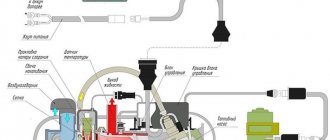
EFP device diagram. To heat the air and start the diesel engine D - 240, 243, there is a special device - the MTZ - EFP electric torch heater, which is installed directly in the tractor inlet manifold.
This heater does not require any targeted maintenance or special settings, since its initial (factory) switching adjustment, as well as the gap between the core and the fitting, are set by the manufacturer itself.
However, you still need to monitor it during the operation of the Belarusian tractor, checking the strength of the fasteners, electrical wiring, fuel pipeline and, if necessary, clean the nozzle in the fitting.
Operating principle
Thanks to the electric current from the battery, supplied to the spiral and electromagnetic coil, the heater is turned on by one toggle switch together with the starter.
In one position, electricity from the battery is supplied to the coil and reduces the voltage to 10 V, and in another position an electromagnetic coil is connected. The control element is located on the instrument panel of the tractor itself, and the entire warm-up takes no more than 15-20 seconds, maintaining a temperature of about 950 degrees.
An electromagnetic coil selects an armature, which is also a valve, and through the resulting hole fuel enters, falling onto a white-hot spiral, where it ignites, allowing the diesel engine to start.
During the startup of the diesel engine D - 240, 243, fuel is delivered by a special boost pump, and direct supply is carried out by a separate dispenser consisting of a triple felt disk clamped with a retaining nut. Thus, the total level of fuel delivered through the dispenser does not exceed 12 cubic meters. cm per minute.
As soon as the diesel engine D - 240, 243 is started, the electromagnetic coil is disconnected from the battery power along with the starter, the armature valve with the help of a spring returns to its original position, closing the hole through which fuel entered the hot spiral, and the operation of the electric torch heater immediately ends my job.
Scheme of EFP-8101/500 tractor MTZ-80, MTZ-82:
1 — fitting bolt; 2 - valve body; 3 - current-carrying terminals; 4 - fitting; 5 - electromagnetic coil; b - spring; 7 — armature with ball valve; 8 — jet; 9 — filament coil; 10 - casing.
Tips and tricks
As mentioned at the beginning of the article, adjustment of the electric torch heater is not necessary, but constant maintenance is required, especially if you take the operation of the tractor in winter seriously.
It’s not difficult to guess how many engine parts are damaged during the spring-summer-autumn period, and therefore good cleaning is simply necessary. Be sure (with the onset of cold weather) to rinse the tank, nozzle and pipeline with some kind of non-freezing solution so that there are no malfunctions in the operation of the EFP and you do not have to use ether, for example, or some kind of blowtorches to start the engine, because ether is quite destructive impact, and the lamps are simply less useful.
1 — fitting bolt; 2 - fuel pipe; 3 - fitting; 4 - valve spring; 5 - valve; 6 — body; 7 - filter; 8 — jet; 9 — body with coil; 10 - filament coil.
Electric torch heater EFP-8101/500
During operation, the heater does not require maintenance.
Rice. 83. Pre-starting electric torch air heater:
1 — fitting bolt; 2 - valve body; 3 - current-carrying terminals; 4 - fitting; 5 - electromagnetic coil; b - spring; 7 — armature with ball valve; 8 — jet; 9 — filament coil; 10 - casing.
Caring for the starter ST-352D starting engine (Fig. 84)
1. Every 240 hours of operation (at maintenance No. 2), check the tightness of the tie rods and the fastening of the relay to the starter.
2. After 1920 hours of operation (through one maintenance No. 3), remove the starter and send it to the workshop for complete disassembly, cleaning, and checking the condition of the main components and parts. Wherein:
a) check the condition of the relay contacts, clean them from dust and dirt. If there is burnt on them, clean or polish them. If the contact bolts at the points of contact with the contact disk show significant wear, they should be rotated 180°;
b) wipe the collector with a clean cloth soaked in gasoline. If the collector is slightly burnt, sand it with fine glass sandpaper. If there is significant wear on the commutator, grind it to a minimum depth and grind it;
c) check the condition of the brushes. The brushes must lie flat against the commutator and move freely in the brush holders;
d) check the spring pressure on the brushes. The force measured by a dynamometer should be in the range of 1000-1400 gf.
Rice. 84. Starter ST-352D:
1 — cover from the collector side; 2 - body; 3 - anchor; 4 - drive side cover; 5 — drive; b - thrust ring; 7 — lifting lever; 8 - electromagnetic relay.
Before assembly, lubricate the starter drive, shaft journal and splines, thrust washers, pins and lever axle with diesel oil. When checking the starter at idle, the latter should consume a current of no more than 50 A, and the armature rotation speed should be at least 5000 rpm.
Classification
Devices used to facilitate the start of engine operation are divided into:
- Heaters operating before starting the power plant increase the temperature of the engine systems, battery electrolyte, oil used by the power unit, etc.
- Devices operating during the startup of the power unit that improve the flammability of the fuel.
Depending on the types of energy, coolants and their circulation circuit used during operation, engine heaters are divided into the following main groups:
- Stationary electric models operating from an alternating current network increase the temperature of the coolant, most often antifreeze, using electric heating elements of various types - induction, which generate heat when resisting current, infrared, electrode and others.
- Autonomous liquid heaters installed at the location of the power plant of a car or tractor, running on gasoline, diesel fuel or gas.
- Heat accumulators are devices that accumulate a certain volume of heated coolant in a thermally insulated container that maintains the temperature of the substance placed in it for up to two days.
- Diesel fuel heaters operating during engine starting from a battery or generator, melting the paraffins contained in the fuel during engine starting. Devices of this type include electric torch devices that increase the temperature of the air used by the engine, devices that heat fuel-air mixtures, and devices that improve the flammability of fuel using flammable liquids.
Among the numerous devices that heat engines before starting them, the most widely used in the CIS countries are electric auxiliary heaters that heat the antifreeze filling the engine cooling system, which include the HYDRONIC 10, Binar and Webasto models, as well as electric torch heaters from various manufacturers.
Engine heater: types and installation on the MTZ tractor
Engine heaters are devices designed to preheat internal combustion engines before starting them in low temperatures, as well as heating the interior, the surface of the windshield and wipers.
By reducing the number of cold engine starts and shortening the period of engine operation in high-load modes, the use of heaters increases the service life of power units, saves fuel and improves driving conditions.
Pre-start electric stationary heaters
Electric internal combustion engine heaters operating from an alternating current network are most common in Scandinavian countries, Canada, the northern regions of Russia and the USA.
In heaters of this type, heating elements are installed in the lower part of the cooling system, and the circulation of the heated coolant occurs due to its temperature diffusion.
The main structural elements of stationary internal combustion engine electric heaters:
- A heating element built into the engine cooling system, placed in a sealed heat exchanger;
- An electronic module for controlling the operation of the device equipped with a timer;
- Battery charging device;
- A fan for supplying heated air to the interior.
Overview of the MTZ-80 cabin
Models with a small cabin are in great demand among buyers due to their compactness. Their cabins are made of thin sheet steel. The inside of the cabin is upholstered with soundproofing material. It is attached to the structure using four rubber shock absorbers, which soften shaking and vibration.
During operation, the driver has a good overview of the area. Windshield wipers are installed under the front and rear windows. The rear window and roof can be opened to allow air flow. For comfort when boarding and driving, the tractor is equipped with two steps and handrails on both sides of the cab.
The tractor driver is provided with a comfortable seat with the ability to adjust the backrest tilt. The height of the chair is adjustable vertically and horizontally.
In front of the seat is a front panel with controls. Under the dashboard there are pedals with a separate brake. To the right of the steering wheel are the hydraulic system control levers and the PTO start lever.
Autonomous pre-heater
The main design elements of an autonomous heater for engine preheating are:
- Boiler equipped with a combustion chamber and radiator;
- Fuel supply system to the combustion chamber, consisting of a fuel pump and pipelines;
- Coolant pump;
- The control mechanisms are a temperature relay, an electronic unit for monitoring the operation of the heater and a device for starting it.
In devices of this type, the heat released when fuel is burned in the boiler chamber heats the coolant circulating in a small circle. The fuel is ignited by spark plugs powered by a car or tractor battery.
The battery also serves as a source of energy for the coolant pump. The device consumes about half a liter of fuel per hour.
Autonomous heaters are often used to increase the efficiency of the standard heating system of a car or tractor while driving in very low temperatures.
Heating the MTZ 82 engine from 220 volts
Practice has shown that a heated diesel engine above 50°C starts at any low ambient temperature, with serviceable and well-functioning fuel equipment, without any problems. This is explained by a decrease in the resistance to rotation in the structural axes of the crank mechanism and the movement of parts in the diesel cylinders, as well as a sufficiently comfortable temperature for ignition of the fuel in the combustion chambers. Starting a warm engine ensures immediate supply of lubricant to the parts, which ensures a soft start and preserves the life of the unit.
Initially, for general warming up, tractor drivers used handicraft methods: before starting, they heated the coolant drained from the block, heated the diesel pan with burners with an open flame or external electric heating devices. Such methods often involve safety violations, are inconvenient and time-consuming.
Heater in the cooling system
For comfortable and safe pre-heating of the engine, there are built-in boilers on the market, which are powered from a general power supply of 220 volts. Heating is carried out by heating elements in the boiler upon contact with the diesel coolant.
Universal instantaneous auto-heater
An example of such equipment are flow-type electric coolant heaters. The device, with its inlet pipe, is connected to the cooling system through a fitting installed instead of a drain valve on the right side of the D 240 engine block. Thus, the heater receives cold liquid for heating. The outlet pipe is connected through a tee to the outlet pipe from the block to the stove. Due to convection, the heated liquid is naturally pushed upward and flows through the outlet of the stove into the diesel block. Such heaters are universal in their application and are used for all types of tractor and automobile engines with liquid cooling; they have the same design with different power heating elements.
Universal flow-through auto-heater for MTZ 80
According to the experience of practitioners, when using a heater with a power of 1.5 to 2 kW/hour, to warm up the diesel engine of the MTZ 80(82) tractor to a temperature of 40-50°C, in cold weather - 20°C, heating can take up to 2 hours.
Boiler for heating coolant MTZ 82/80
Also on sale are special coolant heaters for the D-240,243,245 engine. The device is mounted with a connecting flange on the left side of the engine instead of a plug in the block. The working capacity of the equipment receives cold liquid, heats up and is pushed by gravity back into the cooling jacket. Installation of a heater of this design is possible in the absence of a PD 10 starting engine, that is, in a diesel engine equipped with an electric starter.
MTZ 82 engine with a fluid heater on the block
The appearance on the market of universal auto-heaters with forced circulation of liquid, which are additionally equipped with an electric pump, can significantly reduce heating time. Such devices, naturally, are more expensive and more technologically advanced in their design. Therefore, when purchasing equipment, you need to pay attention to the quality and compliance of the technical characteristics of the device for use when warming up the tractor engine.
Automatic heater Severs+ with pump
Automatic heater with pump
Heating the oil in the sump MTZ 80
This heating method occurs when a diesel sump is slightly re-equipped. There are no specific ready-made developments for the D-240 engine of the MTZ 80(82) tractor on the market. The main task of the modernization is to equip a seat in the wall of the pan for horizontal installation of a heating element at the level of the position of complete immersion in oil. In this case, it is advisable to use heating elements designed for oil heaters powered by a 220-volt network. The condition for choosing a part is a design size that allows it to fit freely in the oil pan without interfering with the placement and operation of the engine oil pump. In this case, the device must be equipped with a thermostat for heating no higher than 80°C. This prevents overheating and fire, which causes the oil to lose its physical lubricating properties.
Heating element in the MTZ 80 pan for heating oil
Installing a heating element in the MTZ pallet
Tena aphid nest in MTZ tray
Installing such a system is somewhat labor-intensive and the success of implementation depends on the qualifications of the mechanic and the material base. The advantage of such heating is the lower placement of the heating element, which allows, along with heating the lubricant, to evenly heat the entire block with an ascending flow of warm air. Pre-heating of the oil in the sump is especially popular on equipment operating in northern weather conditions and is used in parallel with pre-heating of the coolant, which significantly reduces the preparation time for start-up.
Electric flare models
Electric torch heaters operating during the starter cranking period are devices that facilitate engine operation at low temperatures, the basis of which is the heating of the air entering the engine cylinders with the flame of a torch formed when fuel vapors are burned in the engine air intake pipelines.
Main elements of electric torch heaters:
- Torch candle;
- Electromagnetic fuel valve controlling the fuel supply;
- Shutdown relay;
- Fuel supply system - a pump that supplies fuel through pipelines to the spark plugs and a fine fuel filter;
- Switch.
Design and operation of an electric torch heater
TO
category:
Kamaz Ural cars
Design and operation of an electric torch heater
Next: Torch Heater Maintenance
The principle of operation of an electric torch heater is based on heating the air entering the cylinders with a flame formed in the intake pipes during the evaporation and combustion of diesel fuel vapors during the engine cranking period. Model 740 engines of KamAZ-5320, KamAZ-4310 and Ural-4320 vehicles use an electric torch heater of a similar design.
Rice. 2.29. Electric torch candle: 1 - heating element; 2 — heating element casing; 3 - body; 4 - fuel filter; 5 — fuel jet; 6 - tube; 7 - mesh; 8 - nut; 9 - volumetric mesh; 10 - screen
The electrical system of the electric torch heater includes two electric torch plugs, an electromagnetic fuel valve, a thermal relay resistor, a relay for turning on the electric torch plugs, a relay for turning on the generator excitation winding, a control lamp and a power button.
Electric torch spark plugs are screwed into the threaded holes of the engine intake manifolds and connected to the low-pressure line of the fuel supply system in the section between the fine fuel filter and the high-pressure fuel pump. Fuel is supplied to the spark plugs when the engine is started by a low-pressure pump through a fine filter, while the bypass valve of the high-pressure fuel pump and the nozzle valve of the fine fuel filter close the drain fuel lines and ensure the supply of fuel under pressure to the spark plugs with minimal delay time from the opening of the solenoid valve.
The housing (Fig. 2.29) contains an electric heating element, which is a metal casing, inside of which a spiral is pressed into a special filler that has good thermal conductivity and provides electrical insulation of the spiral from the casing. The fuel coming from the power system passes through the filter and nozzle into the heating cavity, where it is heated and evaporated. To obtain a large evaporation surface in a small volume, grids are provided. A screen with two rows of holes for the passage of air prevents the flame from stalling and attenuation when the speed of air movement in the intake pipes increases due to high starter cranking speeds or after starting the engine.
The electromagnetic fuel valve (Fig. 2.30) ensures that the supply of fuel to the flare plugs is turned on (when the valve driven by the solenoid coil is opened) and turned off (when the valve is closed by the spring after the voltage is removed from the coil) in accordance with the control circuit. It is installed on the engine.
Rice. 2.30. Electrical circuit of the starting device: 1— switch for instruments and starter; 2 - relay for turning on and blocking the ground switch; 3 — ground switch button; 4 — “mass” switch; 5 — starter activation relay; 6 — batteries; 7 - backup switch start:ra; 8 — starter; 9 — relay for switching on the generator excitation winding; 10 - voltage regulator; 11 — generator excitation winding; 12 — thermal relay; 13 — starter switch; 14 — relay for switching on spark plugs for maximum heating; 15 — control lamp; 16 — electromagnetic fuel valve; 17 — electric torch candle
A resistor with a thermal relay and additional resistance ensures that the electric torch heater is ready for operation by timely activation of the electromagnetic fuel valve and pre-heating of the heating elements of the torch plugs. The resistor is an open heating coil; The thermal relay is made in the form of contacts made of a bimetallic plate, which close as it warms up. A resistor with a thermal relay and an additional resistance are installed on the cabin panel.
The operation of the electric torch heater is ensured by a special electrical circuit of the starting device (Fig. 2.30), which is an integral part of the vehicle’s electrical equipment. The operation of the electric torch heater is divided into three stages: before starting the engine, during its starting, after starting.
To ensure reliable ignition of the fuel and create a flame in the intake pipes during engine start-up, it is necessary to ensure preliminary heating of the heating elements for 1 ... 2 minutes and timely supply of fuel by opening the electromagnetic fuel valve. The starting device of the electric torch heater is powered from the batteries by turning on the ground switch button along the circuit: “+” batteries, starter terminals, starter relay, ammeter, instrument and starter switch, closed contacts of the battery shutdown relay, ground switch button , winding of the “ground” switch, “—” of the batteries.
Before starting the engine, when turning the switch key to the first (I) fixed “Heating” position, the relay winding circuit is turned on, which leads to the opening of the lower and closing of the upper contacts of the circuit, which includes the starter switch button. When you press the button, power from the batteries is supplied to the heating elements of the spark plugs through a closed circuit: “+” batteries, starter terminals, starter relay, ammeter, switch, relay contacts and buttons, thermal relay resistor, heating elements of the spark plugs, “—” batteries.
Since the thermal relay contacts are open, the heating elements of the candles heat up. In addition, when the button is turned on, power is supplied to the relay winding, which, by opening its contacts, breaks the circuit of the generator's winding winding, protecting the torch spark plugs from the voltage generated by the generator.
After 1...2 minutes, depending on the temperature of the surrounding air, the bimetallic plate of the thermal relay, heating up, bends and closes the contacts, as a result of which the electromagnetic fuel valve opens, allowing fuel access to the spark plugs. At the same time, the control lamp lights up, indicating that the system is ready to start the engine.
To start the engine, you must press the fuel pedal and turn the switch key to the second non-fixed “Start” position. At the same time, the starter relay winding is turned on, closes its contacts and activates the starter traction relay, ensuring that the drive gear is engaged with the flywheel ring and the starter is turned on. At the same time, when you turn the key, the relay winding is turned on, which, by switching its contacts, bypasses the thermal relay resistor. The heating elements of the torch plugs receive the full voltage of the batteries through a button, bypassing the thermal relay spiral, since when the engine cranks with the starter, the voltage at their terminals decreases.
During the start-up period, the low-pressure fuel pump delivers fuel through an open solenoid valve to the pre-heated heating elements of the torch plugs, in which it is dosed, evaporates and, mixing with air, ignites. The flame generated by the movement of air sucked in by the engine in the area of the spark plugs ensures heating of the air entering the engine cylinders, accelerating the ignition of the fuel.
After starting the engine, the released switch key returns to its fixed position under the action of a spring; the relay winding circuit is turned off, and its contacts open the circuit of the traction relay windings, turning off the starter. At the same time, the circuit of the relay winding opens, and the spring, switching its contacts, opens the circuit that ensures full heating of the heating elements of the candles.
If it is necessary to continue the operation of the torch heating after starting the engine and returning the switch key to a fixed position, the driver, in order to ensure further stable operation of the engine, has the opportunity to maintain the combustion of the torch in the intake pipes for some time, keeping the push-button switch on.
When the button is released, the thermal relay and spark plugs turn off, the fuel supply from the valve stops, and the warning light stops lighting. At the same time, the relay winding circuit opens and the relay spring, closing its contacts, turns on the generator excitation winding, thereby turning on the generator set. The electromagnetic heater turns off.
Read more: Maintenance of electric torch heater
TO
category: — Kamaz Ural cars
Do-it-yourself comprehensive repair of the MTZ-80 engine
The MTZ-80 engine produced by the Minsk Tractor Plant is a reliable device with high strength and a long service life. But even the most reliable units can fail at some point, especially if they are not provided with proper and constant care. If the volume of repair work is small, then owners of Belarus equipment in most cases can carry out engine repairs with their own hands.
However, there is a possibility that the tractor will have to be returned for major repairs. The main thing is to understand which faults you can fix yourself, and in which cases you will have to resort to the services of specialists. Let's consider a description of the main causes of power plant failure in MTZ and ways to eliminate them.
What does MTZ engine repair consist of?
First of all, it is necessary to study the technical characteristics of the engines. The tractors of the Minsk Tractor Plant are equipped with four-cylinder D-240 engines, equipped with a water cooling system and running on diesel fuel.
In some diesel units, the D-240L power unit model is installed, which is equipped with a starting engine. During long-term operation of the tractor, breakdowns may occur in all engine systems and some elements may become unusable.
The technical characteristics of equipment are improved from year to year, but many things remain unchanged. That is why general repair recommendations can be given not only for the MTZ-80, but also for the MTZ-82 or MTZ-1221 models.
Maintenance and repair
Despite all its reliability and fault tolerance, electrical wiring may become unusable with use or under the influence of external negative factors.
That is why its periodic inspection and prevention are so important. This work is characterized by increased danger, and for its high-quality implementation it is necessary not only theoretical knowledge, but also practical experience
As for the breakdowns that you encounter most often, the following can be highlighted among them:
- The end consumer of electricity has failed;
- Contact is absent where it should be and is present where it a priori cannot be;
- The contacts have oxidized, resulting in a voltage drop and excessive heating of the problem contacts;
- The contacts installed on the traction relay in the starter burn out;
- The contacts on the switches are faulty.
Conclusion
Electrical wiring in MTZ tractors is a component that requires increased attention and constant monitoring. The slightest problems and disruptions in operation can have the most unpredictable consequences, causing danger both for the vehicle and for the driver working in it.
How to fix a broken engine cooling system
The Belarus engine cooling system is one of the most breakdown-prone parts of a tractor engine. Malfunctions of the cooling system can include both cracks in the cooling jacket and holes formed in the pipes or radiator. You can understand that some kind of similar malfunction has appeared in your tractor by monitoring the fluid level in the cooler: if it decreases quickly, it means there is a leak somewhere. If you notice that the fluid temperature is too high or too low, it may mean that the thermostat is not working properly or the passages are clogged due to scale build-up. The problem may be with the water pump.
If cracks appear in the cooling jacket, they need to be repaired using a welding machine. If the rubber pipes malfunction, you will have to install completely new parts and solder the holes in the radiator. The thermostat, as well as the pipes, will need to be changed. Repaired bearings are easier to handle pump operation. If the bearings become inoperative, the pump will have to be removed and these components replaced with new ones.
The cooling system of wheeled tractors is dual-circuit. In order for the system to work without interruption, you need to fill it with tested liquid. As a rule, antifreeze is chosen - antifreeze diluted with water and special additives that do not allow the elements to wear out due to corrosion.
Repair of power supply and gas distribution systems of the MTZ engine
Let's look at how to fix problems with the power supply system and gas distribution. If you notice interruptions when turning on, the engine power periodically becomes less and less, which means that most likely there is a problem with the power supply of the equipment. If the power supply system is damaged, it is necessary to check that the fuel supply to the pump is working properly; it is likely that the problem is a clogged fuel line. In this case, it is recommended to clean it. If there was no blockage, you need to deal with the pump: if it does not cope with its functions, it will have to be replaced. After checking the pump, if it is working properly, you need to inspect the fine fuel filter; it is because of this that further problems may arise and it needs to be changed.
It should be remembered that the malfunction of the high pressure fuel pump and injector belongs to the most complex category. If you encounter such a problem, you will have to remove parts from the tractor and carry out a major overhaul of the MTZ-82 D-240 engine: such breakdowns cannot be eliminated on your own. In this case, you should pay attention to such advertisements on the websites of car repair shops as: “I will change the fuel pump”, “I will repair the engine”.
Another common problem is wear of the gas distribution device. If the tractor does not start well, it is possible that the problem lies in this device. Difficulty starting the engine may be due to wear on the camshaft, deformation of the valves, or an increase in the distance between the valves. Basically, in case of such breakdowns, the mechanism parts are replaced with new ones or the gaps between several elements are reduced.
CONNECTION AND PRINCIPLE OF OPERATION OF THE MTZ GENERATOR
Let's consider the connection using the example of the G-306 D generator, which was installed on the MTZ-82 tractor for a long period of time.
The positive wire from the battery is connected to the “B” or “+” terminal. In parallel with this terminal there is a connection to the voltage regulator terminal of the same name. The generated voltage from the stator windings is output to the “+” or “B” terminal inside the generator through a diode rectifier. In parallel with this terminal, through a relay, a battery charge indicator lamp is connected.
If the generator is working properly, the warning lamp lights up when the ignition is turned on and goes out when the engine is running. Additionally, some models of MTZ tractors are equipped with an ammeter, which shows the current in Amperes, or a voltmeter, which shows the voltage in Volts. These devices allow the machine operator to quickly receive information about the operation of the generator and the state of the on-board network while the tractor is operating.
Important The most popular gasoline and electric models of Patriot lawn mowers
Terminal “Ш” is connected to a similar terminal of the relay regulator. Through it, voltage is supplied to the excitation coils.
Terminal “M” (ground) is connected to the body (minus) of the tractor, and in parallel - to terminal “M” of the relay regulator. The “M” terminal of the regulator is also connected to the tractor body. A voltmeter installed on the tractor instrument panel to monitor the voltage in the on-board network can be connected to the circuit between the “W” and “M” terminals of the voltage regulator.
Some models additionally have a “D” terminal, to which the starter relay is connected, to block the starter from turning on when the engine is running.
When the engine is not running, the current from the battery is supplied to terminal “Ш”, which is connected to the field winding, which creates the initial electromagnetic field. When the tractor engine starts, rotation from the crankshaft is transmitted through the V-belt to the generator pulley, rigidly mounted on the rotor shaft. When rotating, the rotor rotates the electromagnetic field of the shunted field windings, which, interacting with the stator windings, creates an alternating electric current on them. The current peaks when the protruding parts of the rotor pass the stator windings. To equalize the pulses, the generated current from the stator passes through a rectifier, converted into direct current. The outputs of the rectifier diodes are connected to the “+” or “B” terminal of the generator, from which the output voltage is removed to charge the battery and power the tractor’s electrical appliances.
At the same time, the relay-regulator keeps the current within 14 - 15 volts, for the correct operation of the devices and to prevent overcharging of the battery.
When the engine reaches high speeds, the generator produces a current exceeding the rated value. Passing through the winding of the regulator relay (in the old version), or through transistors (in the modern version), the current, when the values are exceeded, enters the block of resistances, which reduce the strength of the electromagnetic field of excitation, as a result of which the current decreases.
| Comparative characteristics of voltage regulators | ||
| Name | RR 362 B1 | PP 356 |
| Rated voltage, V | 14 | 28 |
| On-board voltage, V | 12 | 24 |
| Load current, A | 3 | 1,5 |
| Applicability | K-700-701-702-703, TL-28, T-40, T-75, SKD-5, MTZ-50, -52, -80-82, D 804, DT 75 | KAMAZ, MAZ, T-150, MTZ-1221 |
| Notes | Has seasonal voltage regulation | — |
Heating system repair
Let's look at how to fix problems with the engine heating system. Due to the fact that the MTZ-80 and MTZ-82 were created back in the days of the Soviet Union, the plant’s engineers were given a very specific task: to adapt the machine to work in all climatic zones of the country. The designers decided to install a special 220V engine preheater on the MTZ-82, which ensured uninterrupted operation of the tractor both on hot and cold days.
In order to make the process of starting the engine easier, an electric torch pre-heater is installed on the MTZ 220V. The pre-starting engine on the MTZ is powered by a battery installed on board the tractor, and the control of the mechanism is started from inside the tractor driver’s cabin. When the heating of the MTZ-82 engine is turned on, the filament heats up in 20 seconds. At the next stage, the electromagnetic winding is connected. Then the fuel valve opens, fuel flows through it onto the filament and ignites there.
The MTZ pre-heater is an element at risk; a large number of tractor breakdowns are associated with it. A knock in the MTZ engine may be associated with a breakdown in this particular element, so you should check the 220 V heater first. Malfunctions associated with this element are quite difficult to solve on your own, but some craftsmen can install a new heater themselves. If you are interested in this approach, collect information on the Internet and begin the repair and installation process of the heater.
A knocking sound at the bottom of the engine may indicate wear on the crankshaft journals. If this is indeed the problem, engine repair will involve changing the shaft liners.
Pre-heaters. Purpose, types
To increase the reliability of engine starting at low temperatures, special devices are used - pre-heaters. Conventionally, they can be divided into two categories:
- Heaters that start before starting the engine in order to increase the temperature of engine components and assemblies, the battery, and also to heat the tractor cabin;
- Devices that heat fuel during a cold engine start to improve the physical characteristics of the fuel-air mixture. Since the start of production, MTZ-80 and MTZ-82 have been constantly modified. In order to improve performance characteristics, various changes are made to the design of the tractor and its systems. Therefore, depending on the year of manufacture and the specific model, the equipment may vary. Both types of pre-heaters are installed on MTZ-80 and MTZ-82.
Repair of MTZ engine lubrication system
Let's figure out how to fix problems with the lubrication system. Oil is one of the key and most important elements in the operation of agricultural machinery, including when it comes to the functioning of its engine. If you notice that the oil level sensor shows too high or low engine oil pressure, this means that the engine lubrication system has become unusable. Malfunctions of this kind may be as follows:
- Clogged oil passages.
- Deterioration of the condition of the oil pump gears.
- Oil filter clogged.
In order to eliminate these problems, it is recommended to clean the lubrication system using special fluids. If the problem is in the oil pump, it needs to be replaced. After replacing and repairing all parts, the required number of liters of new oil is poured into the system. In order to understand which oil is suitable for your car, you need to familiarize yourself with its technical characteristics.
There is a problem with the machine losing power. This may indicate wear on the piston rings of the connecting rod mechanism. This breakdown requires removing all pistons from the power plant and changing the rings of the mechanism.
Repair of the MTZ-1221, MTZ-80 or MTZ-82 engine is carried out in a similar way. Breakdowns in all cases are typical and differ from each other only in the year of manufacture of the tractor. Installing the engine, as well as repairing its main parts, can be done independently, but there are often cases when it is easier to take the car in for repair.
Engine assembly in case of complex breakdowns should be carried out by a specialist: you should not let the situation take its course, as this can lead to even bigger problems.
Suspension diagram for MTZ 82
The suspension is designed to hinge the traction frame with a blade to the main frame of the motor grader and ensure its installation of the blade in various positions that are necessary for the normal functioning of the machine.
The traction frame is suspended from the main frame at three different points. One of which is a ball pin that pivotally connects both frames - this is the front suspension along the motor grader.
There is also a rear suspension, which is carried out using two hydraulic cylinders for lifting the blade, hinged to two eyes of the clamp on the main frame of the motor grader, and ball joints of the transverse beam of the traction frame.
Hydraulic cylinders can either raise or lower the traction frame depending on their activation, and they also connect both frames.