pre-heater for MTZ
Since the creation of the Minsk Tractor Plant in the middle of the last century, more than three million units of equipment have left the factory’s gates. Having switched to the production of wheeled tractors in 1953, the plant became the main supplier of universal row-crop tractors for the entire agriculture of the Soviet Union. In 1974, the plant produced one of the most successful models, the universal row crop tractor MTZ-80. Its main purpose was to be used in agriculture, but the company’s engineers saw great prospects for its use in other sectors of the national economy. The design of the MTZ-80 provided for the possibility of aggregating the tractor with more than 230 types of machines and mechanisms. In 1975, the first serial MTZ-82 was produced. The MTZ-82 tractor became essentially an all-wheel drive modification of the MTZ-80. The presence of a front drive axle not only significantly increased its maneuverability and traction characteristics, but also expanded its areas of application. MTZ-80 and MTZ-82 have proven themselves to be excellent for working in agriculture. They were readily used by public utilities, construction organizations, enterprises and factories, and logging companies. Many modifications of the MTZ-80 and MTZ-82 are produced to this day, and their popularity is always high. When designing the MTZ-80 and MTZ-82, the engineering staff of the enterprise was tasked with creating a tractor capable of operating reliably in all climatic zones of the Soviet Union. Many years of operating experience have shown the correctness of the chosen technical solutions. Minsk tractors showed excellent performance characteristics both in hot regions of Central Asia and in Siberian frosts.
Features of operating diesel engines at low temperatures
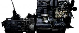
Based on the operating conditions of the MTZ-80 and MTZ-82, a diesel engine of the D-240 series was initially installed on the tractor. The power of the four-stroke, four-cylinder diesel engine was increased to 80 hp. To improve performance characteristics, the engine implemented the principle of a divided combustion chamber with volume-film formation of the working mixture. The complex shape of the combustion chamber creates the necessary turbulence in the air flow, which contributes to a better formation of the working mixture. We can say that Minsk engine builders managed to create a reliable and economical engine. To start the D-240, either an electric starter or a starting engine was used. In conditions of negative temperatures, starting the D-240, like any other internal combustion engine, becomes significantly more difficult. The viscosity of the oil in the lubrication system increases, which requires more force to move engine parts when starting. The atomization of diesel fuel by injectors also worsens due to an increase in its viscosity and an increase in surface tension forces. It is very important that both oil and fuel are suitable for winter use. It is at the moment of start-up that the most intense wear of parts and assemblies occurs, and if fuel and lubricants are selected incorrectly, engine failure can occur. When the ambient temperature drops below 0*C, summer grades of diesel fuel should be replaced with “WINTER”, and at a temperature of -25*C with “ARCTIC”. Failure to comply with this requirement may lead to the formation of solid paraffin fractions in the fuel system, which will inevitably lead to repairs with disassembly of components and assemblies.
Pre-heaters. Purpose, types
To increase the reliability of engine starting at low temperatures, special devices are used - pre-heaters. Conventionally, they can be divided into two categories:
- Heaters that start before starting the engine in order to increase the temperature of engine components and assemblies, the battery, and also to heat the tractor cabin;
- Devices that heat fuel during a cold engine start to improve the physical characteristics of the fuel-air mixture. Since the start of production, MTZ-80 and MTZ-82 have been constantly modified. In order to improve performance characteristics, various changes are made to the design of the tractor and its systems. Therefore, depending on the year of manufacture and the specific model, the equipment may vary. Both types of pre-heaters are installed on MTZ-80 and MTZ-82.
Electric torch heater MTZ-80 and MTZ-82
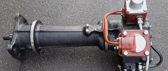
To heat the air and facilitate engine starting at low temperatures, an electric torch pre-heater is installed on D-240 engines. Power is supplied from the on-board battery, and electric current is supplied separately to the filament and the electromagnet winding. Control is carried out from the operator's cabin. When the control switch is turned to the first position, the filament heats up within 15-20 seconds to a temperature of 900-950*C. When the switch is turned to the second position, with the starter starting to operate, the retractor winding of the electromagnet is turned on. By retracting the armature, the coil opens the fuel valve, through which the fuel enters the heated filament, where it ignites. Structurally, the electric torch heater is installed on the engine suction manifold, and ignition of the fuel occurs in its internal cavity. When the starter cranks the crankshaft, heated air is sucked into the combustion chamber, which makes it easier to start the engine. After the engine starts and the starter automatically turns off, the power to the electromagnet coil is also blocked. At the same time, the valve closes, cutting off the fuel supply. The heater operation ends.
Preheater PZHB-200B
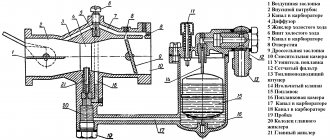
To ensure reliable engine starting in the autumn-winter period, a removable heater PZHB-200B can be installed on MTZ-80 and MTZ-82. During the summer, it is removed from the tractor and stored separately. PZHB-200B is installed on the cylinder block, having previously removed the plug present there. It is designed to increase the engine temperature, warm up the oil and coolant before starting the engine. It has a combustion chamber in which a mixture of fuel and air supplied there burns. Hot gases, passing through the boiler flues, heat the coolant in the outer and inner jackets of the boiler. The heated liquid then enters the engine cooling system. The heated liquid circulates in the boiler and cooling system, which leads to pre-heating of the engine. When the engine temperature reaches 30-35*C, the heater should be stopped, then the engine should be started.
Currently, various manufacturers offer preheaters that use external sources of electric current. The operating principle is similar to the operating principle of PZHB-200B, however, instead of a heater boiler using fuel and a glow plug, electric heating elements of various capacities are installed. The higher the power, the less time is required for pre-heating of the engine. Such heaters are powered from an ordinary 220V alternating current network. If you have a power source, this is quite convenient, but when working in the field far from energy sources, such heaters cannot be used.
Watch video - Pre-heater at MTZ
Share link:
Similar
traktorservice.ru
What does MTZ engine repair consist of?
First of all, it is necessary to study the technical characteristics of the engines. The tractors of the Minsk Tractor Plant are equipped with four-cylinder D-240 engines, equipped with a water cooling system and running on diesel fuel.
In some diesel units, the D-240L power unit model is installed, which is equipped with a starting engine. During long-term operation of the tractor, breakdowns may occur in all engine systems and some elements may become unusable.
The technical characteristics of equipment are improved from year to year, but many things remain unchanged. That is why general repair recommendations can be given not only for the MTZ-80, but also for the MTZ-82 or MTZ-1221 models.
Design and operation of an electric torch heater
Construction machines and equipment, reference book
Category:
Kamaz Ural cars
Design and operation of an electric torch heater
The principle of operation of an electric torch heater is based on heating the air entering the cylinders with a flame formed in the intake pipes during the evaporation and combustion of diesel fuel vapors during the engine cranking period. Model 740 engines of KamAZ-5320, KamAZ-4310 and Ural-4320 vehicles use an electric torch heater of a similar design.
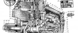
Rice. 2.29. Electric torch candle: 1 - heating element; 2 — heating element casing; 3 - body; 4 - fuel filter; 5 — fuel jet; 6 - tube; 7 - mesh; 8 - nut; 9 - volumetric mesh; 10 - screen
The electrical system of the electric torch heater includes two electric torch plugs, an electromagnetic fuel valve, a thermal relay resistor, a relay for turning on the electric torch plugs, a relay for turning on the generator excitation winding, a control lamp and a power button.
Electric torch spark plugs are screwed into the threaded holes of the engine intake manifolds and connected to the low-pressure line of the fuel supply system in the section between the fine fuel filter and the high-pressure fuel pump. Fuel is supplied to the spark plugs when the engine is started by a low-pressure pump through a fine filter, while the bypass valve of the high-pressure fuel pump and the nozzle valve of the fine fuel filter close the drain fuel lines and ensure the supply of fuel under pressure to the spark plugs with minimal delay time from the opening of the solenoid valve.
The housing (Fig. 2.29) contains an electric heating element, which is a metal casing, inside of which a spiral is pressed into a special filler that has good thermal conductivity and provides electrical insulation of the spiral from the casing. The fuel coming from the power system passes through the filter and nozzle into the heating cavity, where it is heated and evaporated. To obtain a large evaporation surface in a small volume, grids are provided. A screen with two rows of holes for the passage of air prevents the flame from stalling and attenuation when the speed of air movement in the intake pipes increases due to high starter cranking speeds or after starting the engine.
The electromagnetic fuel valve (Fig. 2.30) ensures that the supply of fuel to the flare plugs is turned on (when the valve driven by the solenoid coil is opened) and turned off (when the valve is closed by the spring after the voltage is removed from the coil) in accordance with the control circuit. It is installed on the engine.
Rice. 2.30. Electrical circuit of the starting device: 1— instrument and starter switch; 2 - relay for turning on and blocking the ground switch; 3 — ground switch button; 4 — “mass” switch; 5 — starter activation relay; 6 — batteries; 7 - backup switch start:ra; 8 — starter; 9 — relay for switching on the generator excitation winding; 10 - voltage regulator; 11 — generator excitation winding; 12 — thermal relay; 13 — starter switch; 14 — relay for switching on spark plugs for maximum heating; 15 — control lamp; 16 — electromagnetic fuel valve; 17 — electric torch candle
A resistor with a thermal relay and additional resistance ensures that the electric torch heater is ready for operation by timely activation of the electromagnetic fuel valve and pre-heating of the heating elements of the torch plugs. The resistor is an open heating coil; The thermal relay is made in the form of contacts made of a bimetallic plate, which close as it warms up. A resistor with a thermal relay and an additional resistance are installed on the cabin panel.
The operation of the electric torch heater is ensured by a special electrical circuit of the starting device (Fig. 2.30), which is an integral part of the vehicle’s electrical equipment. The operation of the electric torch heater is divided into three stages: before starting the engine, during its starting, after starting.
To ensure reliable ignition of the fuel and create a flame in the intake pipes during engine start-up, it is necessary to ensure preliminary heating of the heating elements for 1 ... 2 minutes and timely supply of fuel by opening the electromagnetic fuel valve. The starting device of the electric torch heater is powered from the batteries by turning on the ground switch button along the circuit: “+” batteries, starter terminals, starter relay, ammeter, instrument and starter switch, closed contacts of the battery shutdown relay, ground switch button , winding of the “ground” switch, “—” of the batteries.
Before starting the engine, when turning the switch key to the first (I) fixed “Heating” position, the relay winding circuit is turned on, which leads to the opening of the lower and closing of the upper contacts of the circuit, which includes the starter switch button. When you press the button, power from the batteries is supplied to the heating elements of the spark plugs through a closed circuit: “+” batteries, starter terminals, starter relay, ammeter, switch, relay contacts and buttons, thermal relay resistor, heating elements of the spark plugs, “—” batteries. Since the thermal relay contacts are open, the heating elements of the candles heat up. In addition, when the button is turned on, power is supplied to the relay winding, which, by opening its contacts, breaks the circuit of the generator's winding winding, protecting the torch spark plugs from the voltage generated by the generator.
After 1...2 minutes, depending on the temperature of the surrounding air, the bimetallic plate of the thermal relay, heating up, bends and closes the contacts, as a result of which the electromagnetic fuel valve opens, allowing fuel access to the spark plugs. At the same time, the control lamp lights up, indicating that the system is ready to start the engine.
To start the engine, you must press the fuel pedal and turn the switch key to the second non-fixed “Start” position. At the same time, the starter relay winding is turned on, closes its contacts and activates the starter traction relay, ensuring that the drive gear is engaged with the flywheel ring and the starter is turned on. At the same time, when you turn the key, the relay winding is turned on, which, by switching its contacts, bypasses the thermal relay resistor. The heating elements of the torch plugs receive the full voltage of the batteries through a button, bypassing the thermal relay spiral, since when the engine cranks with the starter, the voltage at their terminals decreases.
During the start-up period, the low-pressure fuel pump delivers fuel through an open solenoid valve to the pre-heated heating elements of the torch plugs, in which it is dosed, evaporates and, mixing with air, ignites. The flame generated by the movement of air sucked in by the engine in the area of the spark plugs ensures heating of the air entering the engine cylinders, accelerating the ignition of the fuel.
After starting the engine, the released switch key returns to its fixed position under the action of a spring; the relay winding circuit is turned off, and its contacts open the circuit of the traction relay windings, turning off the starter. At the same time, the circuit of the relay winding opens, and the spring, switching its contacts, opens the circuit that ensures full heating of the heating elements of the candles.
If it is necessary to continue the operation of the torch heating after starting the engine and returning the switch key to a fixed position, the driver, in order to ensure further stable operation of the engine, has the opportunity to maintain the combustion of the torch in the intake pipes for some time, keeping the push-button switch on.
When the button is released, the thermal relay and spark plugs turn off, the fuel supply from the valve stops, and the warning light stops lighting. At the same time, the relay winding circuit opens and the relay spring, closing its contacts, turns on the generator excitation winding, thereby turning on the generator set. The electromagnetic heater turns off.
Read more: Maintenance of electric torch heater
Category: — Kamaz Ural cars
Home → Directory → Articles → Forum
stroy-technics.ru
Electric torch heater
Category - Pre-starting heater
An electric torch heater is installed in the intake manifold and serves to heat the air to facilitate diesel starting.
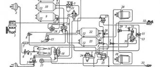
The diagram for connecting the electric torch heater to the electrical circuit is shown in the figure “electrical diagram of the MTZ-80/82 tractor”. Electric current from the battery is supplied separately to the electromagnet coil and the spiral. The heater is turned on using the same switch VK316-B 21 as the starter.
When the switch is turned on in the first position, current is supplied to the filament coil circuit through the control element PD-50-V 18 and the additional resistance SE50-V 17.
The coil heats up within 15-20 seconds. After this time, the temperature of the coil reaches approximately 950 °C.
When switch VK316-B 21 is turned on to the second position, the electromagnet coil is turned on simultaneously with the starter. In this case, the heater coil remains switched on, and the control element and additional resistance are bypassed.
Pre-starting electric torch heater
- fitting bolt
- fuel pipe
- union
- valve spring
- valve
- valve body
- filter
- jet
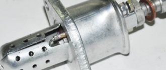
- body with coil
- filament coil
When current passes through the electromagnet coil 9, the armature 5, placed inside it and serving as a valve, moves upward, opening a hole through which fuel flows from the valve body 6 onto the hot spiral 10 and ignites. Fuel is supplied by gravity from the electric torch heater tank.
The permissible fuel consumption (no more than 12 cm3/min) is ensured by installing 1 metering element in the fitting bolt.
After starting the diesel engine, simultaneously with the automatic shutdown of the starter (relay PC502 is de-energized), the power from the electromagnet coil is turned off and the armature, under the action of a spring, moves to its original position, closing the hole in the valve body. The fuel supply to the spiral stops.
When the key of the VK-316-B switch is returned to its original off position, the supply of current to the incandescent coil is stopped - the heater is de-energized.
Tags: electric torch heater
Related materials:
tractor-mtz80-mtz82.ru
Electrical diagram of the MTZ 82 tractor
The electrical equipment of the MTZ 82 tractor is intended for starting and maintaining the engine, powering electrical appliances and other devices, as well as for operating the tractor and agricultural machinery at night, both when performing agricultural work and when using the tractor for transport work.
The rated voltage in the system is 12 V. The tractor electrical system includes:
- a) sources of electrical energy - batteries and an alternating current generator working in conjunction with a relay regulator;
- b) engine starting system - electric starter with remote activation; starter relay relay wiring diagram, additional resistance control element of the electric torch heater; electric torch heater; 3-position heater and starter switch;
- c) lighting and light signaling - front and rear lights; front direction indicators; tractor rear lights, brake lights and direction indicators; license plate light; instrument panel indicator lamps; cabin lighting; portable lamp; turn signal relay; central switch and light switches;
- d) electric motor of the cabin air heating and cooling unit with a switch;
- e) an electric motor with a windshield wiper and a switch;
- f) connecting panels; plug connectors; wiring harnesses and fuse blocks;
- g) instrumentation - indicators of water temperature and oil pressure; ammeter; air pressure gauge; tachospeedometer
Electric torch heater for MTZ
The mechanism is installed on the diesel inlet pipeline of the tractor.
Designed to heat air.
Makes it easier to start the engine at low temperatures.
In this article we will look at the design of an electric torch heater and the technical features of the unit.
Components of the MTZ heater
The system includes two candles.
MTZ parts are screwed into the threaded holes of the tractor motor manifolds. Connect to the low pressure line.
Candles consist of the following components:
- A heating element;
- casing;
- Frame;
- Fuel filter;
- Screen;
- Fuel jet;
- Spiral;
- A tube;
- Net;
- Screw.
Fuel is supplied to the electric torch spark plugs when the tractor engine is started by a booster pump through a special fine filter. The valves close the fuel drain lines.
This ensures minimal delay time when supplying fuel. In addition to candles, the MTZ heater includes:
- Valve;
- Resistor;
- Switching relay;
- Indicator lamp;
- Switch;
- Coil relay.
Operating principle
The operation of an electric torch heater is divided into three stages:
- Before starting the engine;
- At the moment of launch;
- After launch.
Inside the housing there is a valve and an electromagnet winding.
Fuel flows from the tank through the hollow bolt.
An incandescent coil with a casing having several holes is fixed in the lower part.
The MTZ heater is started by the same switch as the starter. The lever is turned to the first position.
The current approaches the spiral through the control element and through the additional resistance. It is located in the cockpit. The spiral heats up in twenty seconds to a temperature of 950 degrees.
When the switch is turned to the second position, the electromagnet turns on along with the starter. The spiral is also involved. The resistance and control element are switched off.
When current passes through the coil, the valve moves up. A hole opens for fuel to flow from the housing onto the hot spiral. Ignition occurs. The air passing through the pipeline warms up.
When starting the diesel engine of a modern tractor, the starter is turned off and the coil is de-energized. The valve moves down under the influence of a spring. The hole is closed.
Fuel supply stops.
Technical features of the MTZ heater
High-strength electric torch heaters are equipped with switch-on timers.
Some devices are also available with remote control. The combined use of a heater with pouring low-viscosity oils into the engine makes it possible to reduce the start-up temperature by 10-15 K.
The most advanced domestic version is the design of the Vladimir Automobile Plant. Among foreign analogues, units from Lucas are considered the most effective.
The electric torch heater can operate on gasoline and fuel. Therefore, the device is suitable for installation on any engine. The MTZ heater can be used after starting the engine at idle speed.
The engine will warm up faster.
The smoke will decrease and the toxicity of exhaust gases will decrease. The time to warm up a tractor engine using electric torch heaters ranges from 20 minutes to several hours.
It all depends on the power and type of installed device. The presence of the MTZ heater allows the use of tractor equipment that is not adapted to low temperatures in winter.
The use of the unit facilitates engine maintenance. Reduces the negative impact of cold air.
mtzrostov.ru