One of the most important components of an overhead crane is the load trolley - it ensures the operation of the crane with a load: lifting and lowering, as well as movement of the load along the bridge. Different types of cranes require different functions, so the design of an overhead crane trolley, its lifting capacity, and the number and types of equipment installed on it are all determined by the design of the truck and its purpose. On small cranes with low lifting capacity, instead of a trolley, a simply hoist with a hook is often installed.
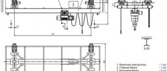
Construction of a cargo trolley for an overhead crane
Rice.
13. General purpose crane trolley with lifting capacity 20/5 t Fig. 14. General purpose crane trolley with lifting capacity 80/20 t
Rice. 15. General purpose crane trolley with lifting capacity 250/32 t
The mechanisms are placed on the trolley frame in such a way as to ensure uniform load on all running wheels. Therefore, lifting mechanisms use drums with two cuts in different directions and double pulleys, which makes it possible to lift the load vertically and, when installing the middle of the drum along the longitudinal axis of the bridge, transfer a uniform load from the gravity of the lifted load to the running wheels. When using two lifting mechanisms, main and auxiliary, the main lift mechanism is placed in such a way that the drive wheels experience more load than the non-drive wheels. The running gear of heavy-duty crane trolleys (more than 50 tons) is made on balancing trolleys, which make it possible to more evenly distribute the load on the main beams of the crane bridge from the action of their gravity, as well as the gravity of the lifted load.
The design of the trolley is largely determined by the design of the crane bridge span, which can be double-girder or single-girder. Crane trolleys of double girder cranes can move along the upper and lower chords of the main beams. The trolleys move on rails laid on the upper chords of the main beams. The mechanism for moving trolleys, as a rule, is made with a low-speed shaft.
The track of the trolleys mainly depends on the length of the drum of the load lifting mechanism and for light-duty cranes it is 1.4, 2.0 and 2.5 m.
In cranes with single-girder bridges, which are becoming increasingly widespread, the most rational option is to use cantilever-type trolleys. Cantilever trolleys are made either with side guide rollers (Fig. 16, a) or with reverse rollers (Fig. 16.6), which hold the trolley on the main beam from tipping over. The running wheels (drive and non-drive) of the bogie rest on a sub-carriage rail, which is usually located above the wall of the main beam.
The trolley of a magnetic crane (Fig. 17, a) with a suspension of a cargo magnet on a hook suspension differs from the trolley of a general-purpose heavy-duty crane only by the presence of a cable drum connected directly or by a mechanical (gear, chain) transmission with the drum of the lifting mechanism, which allows synchronous lift the electromagnet to select its power cable.
Rice. 16. Cantilever trolleys for single-girder overhead cranes: a - with side guide rollers; b - with reverse rollers
The trolley of the grab crane (see Fig. 17.6) has two identical cargo winches: lifting and closing, and the magnetic grab crane (see Fig. 17, c) has a main lifting mechanism for lifting replaceable electromagnets or motor grabs and an auxiliary mechanism lifting when using the crane as a hook crane.
The trolleys of magnetic cranes with a flexible traverse suspension (Fig. 17, d, e) have two cargo drums rigidly connected by an intermediate shaft, mounted on the trolley frame depending on the location of the traverse (longitudinal or transverse location relative to the crane bridge). The rotating trolley of a magnetic crane with a flexible traverse suspension (Fig. 18) consists of a lower part with a movement mechanism and an upper rotating part with installed lifting and turning mechanisms.
Rice. 17. Diagrams of the arrangement of mechanisms on the trolleys of special-purpose overhead cranes: a - magnetic crane trolley; b - grab crane trolley; c — trolley of a magnetic grab crane; d, e - magnetic crane trolley with a flexible suspension of the traverse, located respectively in the longitudinal and transverse directions relative to the bridge; 1 — trolley frame; - 2 — running wheel; 3 - cable drum; 4 - drum; 5, 9 — gearbox, respectively, of the lifting and moving mechanism; 8, 13 - brake, respectively. lifting and moving mechanism; 7 — high-speed shaft of the lifting mechanism; 8, 10 - electric motor of the lifting and moving mechanism, respectively; 11 — closing winch; 12 — auxiliary lift mechanism; 14 — lifting electromagnet
Rice. 18. Rotating trolley of an overhead magnetic crane with a flexible suspension of the traverse: 1 - electric motor; 2 - gearbox; 3 — low-speed transmission shaft; 4 — running wheel of the lower part; 5 - traverse; 6 — lifting mechanism; 7 - ring current collector; 8 — mechanism for turning the upper part; 9 - circular rail; 10 - lower part; 11 — frame of the upper rotating part
The frames of the trolleys are made of welded sheets or rolled steel, in rare cases cast. To install mechanisms, there are plates on the bogie frame, the contact surface of which is processed after welding. The roll-out axle boxes of the trolley movement mechanism are mounted on plates, the processing of which is subject to very high requirements, since inaccurate installation of the running wheels on the trolley frame leads to their rapid wear. For the passage of rope branches of the pulley suspension, windows are made in the cart flooring. In Fig. 19, a shows the metal structure of a medium-duty crane trolley with one lifting mechanism, in which the load-bearing beams of the U-shaped trolley are made of bent sheet metal. The trolley frames (Fig. 19.6) of heavy-duty cranes are assembled from individual elements connected to each other by assembly joints; For ease of maintenance, such carts are equipped with ladders.
Utility model formula
1. A mechanism for lifting loads of an overhead crane, mainly for nuclear energy facilities, containing two drums, two electric motors, a dual gearbox, the high-speed shafts of which are connected to the shafts of the electric motors, and the low-speed shafts are connected to the drums, two brakes installed on the high-speed shafts of the gearbox, a lifting trolley, load gripper and two pulleys, the ropes of which are stored through blocks mounted on the lifting trolley and on the load gripper suspension, and attached at one end to the drums, characterized in that it is equipped with three pairs of pulley blocks, which are attached to one of the ends and in the middle part span structure of the crane, load limit sensors, sensors for extreme positions of load gripping, which interact with the axes of the drums, a device for controlling the speed of rotation of the drums and a double-arm balancing lever, fixed with its middle part at the second end of the span, while the pulley ropes running from the drums are stored sequentially through blocks , fixed in the middle part of the span, at one end of the span, then through blocks attached to the load-carrying trolley and load-gripper suspension, and with their other ends attached to the opposite shoulders of the double-arm balancing lever, and the drums, gearbox, electric motors and brakes are mounted on the platform, rigidly attached to the crane span.
2. The mechanism for lifting the load of an overhead crane according to claim 1, characterized in that the load limit sensors are mounted in the axes of pulley blocks mounted at the end of the span.
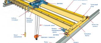
Overhead crane design
An overhead crane is a crane with a load-handling device suspended from a load trolley or hoist that moves along a movable steel structure (bridge). Thanks to its design, an overhead crane can move a load to any point in the working area limited by the lengths of the crane and span beams.
An overhead crane can be divided into two main groups of elements: mechanical components and electrical equipment , which allows you to control the operation of the crane.
Additional features and equipment
For different purposes and structures of the overhead crane, the cargo trolley can be equipped with several load lifting devices synchronized with each other. In addition, in some cases there may be two or more cargo trolleys themselves - if this is required for handling large-sized cargo.
The design of an overhead crane trolley implies the presence of elements and systems that ensure the availability of mechanisms for maintenance, repair and replacement, protect the mechanisms from harmful influences (dust, moisture, chemicals, etc.), allowing automated control of the device, etc.
Mechanical components of an overhead crane
Crane bridge , which also has another name - the span beam - is the supporting structure of the crane, designed for the movement of a cargo trolley along it. A crane bridge consists of one or two span beams connected to end beams, which in turn can move the entire overhead crane structure along the crane beams. One or two load trolleys can be located on the crane bridge, on one or two independent tracks.
An overhead crane load trolley or simply a crane trolley is designed to move and lift loads along the span (span beam of an overhead crane). The design of the trolley is a frame welded from transverse and longitudinal beams, which rests on running wheels and has a very rigid structure. On the frame of the trolley there is a lifting mechanism (auxiliary and main lifts), a mechanism for moving the trolley itself along the crane bridge, a pantograph, as well as safety devices. A hoist or hoist is installed on single-girder overhead cranes; a double-girder crane is equipped with a load trolley.
A hoist or hoist is a suspended lifting device with a manual or mechanical drive (usually electric). Hoists are widely used both as an independent lifting mechanism and in trolleys of single-girder overhead cranes.
An electrically driven hoist (telpher) is a winch with a gearbox, electric motor, drum or sprocket, brake and hook suspension. There are stationary and mobile (mechanized) hoists, suspended from special carts moving along suspended monorail tracks.
The end beam is an integral part of the overhead crane and serves as a mechanism for moving the crane bridge along the crane tracks located perpendicularly and at the same time serves as a bridge support. The end beam consists of a body, wheel blocks and a gear motor. The end beams included in the overhead crane are usually called a set of end beams.
The crane runway is used to move the overhead crane along the crane beam. For an overhead crane, the crane runway can be made supporting (for supporting overhead traveling cranes) and suspended (for suspended overhead traveling cranes). Depending on this, the crane runway can be of two types: rail or beam. The rails used are square or strip steel, railway rails or special crane rails.
Crane beams are the main load-bearing element of the crane structure, receiving and transmitting crane loads to a fixed base and ensuring safe operation of the crane along the entire path of its movement. There is a crane runway on the crane beam. Crane beams can be made of metal beams or reinforced concrete. Crane beams are a structural element of a crane trestle.
A crane trestle is a global engineering structure consisting of supports and a span horizontal structure, which is the supporting structure for an overhead crane. The crane trestle can be installed in a production area or in the open air.
The built-in type crane trestle is used in production facilities or workshops and is installed on supports. Workshop columns can be used as supports, on which crane beams are installed. Also, the crane trestle can have an independent design. In this case, columns or trusses made of metal structures with a flanged base are used as supports.
On open sites, in the open air, an open crane rack is installed. The columns of the overpass are installed on their own foundation.
In accordance with the Rules, for convenient and safe maintenance of cranes, their mechanisms and electrical equipment located outside the cabin, the design of overhead cranes provides for the installation of appropriate galleries , platforms and stairs .
Based on the type of crane bridge suspension, overhead cranes are divided into supporting and suspended .
A supporting overhead crane is a crane whose end beam rests on the crane runway rails located on top of the crane beam.
An overhead overhead crane is a crane whose end beam is attached to a crane runway located on the lower belt of T-beams or I-beams.
Based on the number of spans, overhead cranes are divided into single-girder and double-girder . Accordingly, the overhead crane has either one or two spans. Double girder cranes are more stable, have a more even load distribution and can lift more weight.
The control cabin is located on the crane bridge in a place that provides the best visibility and safety for the crane operator; most often it is located at the edges or in the middle of the crane bridge span. Sometimes the control cabin is suspended from a cargo trolley. In some cases, to improve visibility, the cabin has the ability to move autonomously along the crane span.
Electrical equipment of an overhead crane
The electrical equipment of an overhead crane is divided into main equipment , which ensures the movement of the bridge and cargo trolley and lifting/lowering of the load, and auxiliary equipment , which performs various additional functions not directly related to the main operation of the crane.
Basic equipment
- AC electric motors;
- control systems - controllers, contactors, control relays, magnetic starters, switches and other equipment that allows you to control electric motors;
- electromagnets, electrohydraulic pushers and other devices that ensure the operation of locking brakes;
- circuit breakers, fuses, current relays and other electrical protection devices;
- load limiters, end position limiters and other mechanical safety devices.
Auxiliary equipment
- additional lighting equipment;
- sound alarm devices;
- heating devices (electric furnace in the crane control cabin);
- measuring equipment;
- additional protection.
Power supply of mechanisms
Power supply to the crane elements can be carried out in two ways: trolley lines or daisy chain cable systems.
The design of an overhead crane includes such elements of electrical equipment as an electrical cabinet, control panel, conductor, etc.
An electrical cabinet is a metal box that contains the electrical equipment of the crane - controllers, contactors, control relays, magnetic starters, resistors, frequency converters, switches and other equipment that allows you to control electric motors.
The overhead crane can be controlled by a console (the operator controls the crane using a control panel from the floor) or from a control cabin installed on the overhead crane. Depending on this, the overhead crane can be equipped with either a control panel or a control cabin.
The control panel is a device for monitoring and controlling crane equipment. Control panels are divided into pendant panels and radio-controlled panels .
Overhead cranes - purpose, design, design features
In metallurgy and construction, in the production workshop and warehouse, in transport and repair shops, when working with bulk and dangerous goods, overhead cranes are used to move large cargo, non-demountable units and much more. This equipment is designed for intensive work in a wide variety of, sometimes extreme, conditions.
Purpose and design of an overhead crane
An overhead crane is used to move cargo around a workshop, warehouse, or other production facility. A crane bridge with a cargo trolley attached to it moves along the crane tracks laid along the walls, lifting and lowering the load.
According to the bridge design, cranes are divided into:
- Single beam. The bridge consists of one I-beam, at the ends of which end beams with running wheels are installed. In addition to the main cargo trolley, an additional console type can be installed. Cranes of this type are lightweight, but their lifting capacity, as a rule, does not exceed 10 tons.
- Double beam. Structurally, the bridge is composed of two rigid beams with end beams equipped with running wheels. In addition to the main one, the cargo trolley can be equipped with auxiliary lifting mechanisms. This type of crane has a large lifting capacity and is controlled from the cabin or remotely.
Diagram of an overhead crane
Based on the type of fastening, overhead cranes are divided into 2 types:
- Hanging. The load trolley moves along the lower plane of the bridge beam.
- Supporting. The load trolley moves along the upper plane of the support beam. This design provides maximum load capacity.
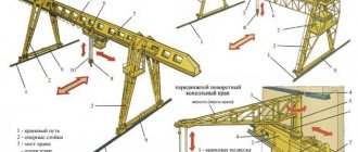
There are several types of overhead cranes, different from traditional ones, moving along parallel crane tracks:
- Radial. The crane rotates along a ring rail around a support rigidly fixed in the center of the working platform.
- Chordata. Movement is carried out along a ring rail. Due to design features, the area of the ring served by the crane is smaller than that of a radial ring with the same radius of rotation.
- Annular. The crane moves on two ring rails of different diameters. To prevent slipping, the running wheels are made of different diameters.
- Turning. The crane bridge is equal to the diameter of the ring rail along which movement occurs. Unlike the radial crane, there is no central support beam, and the crane can perform loading and unloading operations at any point inside the circle limited by the crane tracks.
Price
The final cost will depend on several factors:
- required carrying capacity,
- type and design of cargo lift,
- operating conditions and operating mode,
- the need to install additional equipment.
If you need to purchase cargo equipment, leave a request on the website or call our employees, they will help you select the necessary components and place an order. In addition, the Kranmontazh company is ready to manufacture an overhead crane trolley according to the drawings provided by the customer. Specific terms of interaction, prices, discounts and terms, delivery options and guarantees are determined in each case individually.
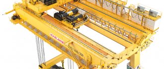
Overhead crane structure
The general structure of an overhead crane consists of a single- or double-girder bridge with a load trolley moving along it. Both the bridge and the bogie are equipped with the necessary electrical equipment and mechanical components. The mechanism is controlled from a suspended cabin or from a remote control when the operator is on the floor of the workshop or outside the work site.
Installation of crane tracks can be carried out either on a free-standing crane trestle or using the floor, columns, and rafter trusses of the workshop.
The photo shows the structure of an overhead crane
Next, we will consider the design of various mechanisms of an overhead crane.
Brake system
The brake system is used to hold the load or control the speed of its movement (drain brake), stop the movement of the crane bridge or cargo trolley (drain brake). Traditionally, lifting mechanisms use closed (closed) brakes that block normal movement. When you press the pedal or handle, the mechanism is released. In an emergency, in the event of a breakdown or stoppage of any crane unit, such a brake mechanism is automatically activated.
Shoe brakes provide smoother and faster braking.
Lifting mechanisms
The crane trolley contains a mechanism for lifting and lowering the load. In addition to the main one, one or two auxiliary mechanisms can be used, the lifting capacity of which is 3-10 times less than the lifting capacity of the main one, depending on the class of the crane.
The components of any of them are:
- Drive motor.
- Transmission shafts.
- Gearbox.
- Cargo ropes with a drum for winding.
Diagram of the overhead crane lifting mechanism
To handle loads of more than 80 tons, an additional gearbox or reduction gear is used. To increase the traction force, a chain hoist is used, the most common type of which is a double multiple hoist. Thanks to it, the cable is wound evenly onto the drum from both ends, thereby balancing the load on the drum supports and the entire span of the bridge.
Crane tracks
The purpose of crane tracks is to ensure uniform distribution of the weight of the overhead crane on the foundation and movement of the crane beam along these tracks.
For support single girder cranes with low lifting capacity, ordinary railway rails are used as guides. For mechanisms with a lifting capacity of 20 tons or more, special crane rails are used. The basis for them is most often a steel I-beam. Taking into account the weight of the crane itself and the cargo, as well as the speed of movement along the crane tracks, increased requirements must be applied to the quality of their installation, eliminating the possibility of the crane derailing. To prevent this, the width of the wheels must be greater than the width of the rails used. So, when using cylindrical wheels, their width should be 30 mm or more greater than the width of the rail. For bevel wheels this value must be at least 40 mm.
The rails must be laid with a thermal gap, and the height difference between them must be no more than 2 mm. At large values, a strong shock load on the wheels occurs.
Electrical equipment
Special requirements are imposed on the electrical equipment of overhead cranes, including an operating mode in which up to several hundred short-term switching on and off can be performed within an hour, overloads that occur during acceleration and braking of the crane trolley and the crane itself, and changes in travel speeds.
Braking system
In order to control the process of lifting and moving a suspended load, a release brake is used. In most cases, the principle brake circuit of an overhead crane with a lifting capacity of 10 tons has a closed structure, that is, the movement of the load is blocked in the normal state, and to move it you need to release the release lever.
If an emergency situation occurs (for example, broken cables), the device automatically stops the movement of the crane.
Shoe brakes are highly reliable. To hold the moving load, the pads are activated and block the cable mechanism.
Design
The trolley frame has a very rigid structure. It contains:
- lifting mechanism;
- object for current distribution;
- security mechanism.
movement mechanism;
The safety mechanism ensures normal movement and lifting of loads. Safety devices include items that limit the lifting height and load capacity.
Also related to safety is a lifting mechanism that automatically turns off when the load is lifted to the maximum height, as well as when lifting a load that exceeds the permissible weight by 10%. Mechanisms that measure the mass of the load, as well as a ruler, are fixed on the trolley. Switches are installed on the crane bridge that limit the movement of the trolley in extreme directions.
When the trolley approaches the extreme position, the ruler interacts with the switches and further movement of the trolley is automatically blocked.
If for some reason the switches do not work, there is another device for this purpose that blocks the movement of the trolley in the extreme position - it is called a buffer.
Handrails are always installed on the trolley. They must be there to ensure safety during inspection or breakdown of crane mechanisms.