In the article we will look at the design features of the electrical circuit of the drive elements of overhead cranes. There are many manufacturers on the market, each of which has implemented its own technological developments. The component has a wide range of parameters, which we will analyze further.
Schematic electrical diagrams of overhead cranes
An electric drive is a full-fledged electromechanical type system, the main task of which is to drive machines and equipment, as well as to constantly control movement. The main purpose of the application is the uninterrupted implementation of the technological process.
The design of the devices is regularly modernized, thanks to which we can safely say that the unit is a combination of a list of electrical machines and management systems. The power unit consumes about 60% of the total electricity and emits a large share of mechanical energy among all system components.
general characteristics
Drives installed in lifting machines operate in intermittent mode at high switching frequencies. The design is functional, which makes it possible to work in a wide range of speed adjustments. Reliability ensures a high level of functionality even under significant overloads during acceleration and deceleration of units.
Electric bridge drive
construction
crane
is a device that is sold in several modifications of direct and alternating currents. The category also includes the following auxiliary devices:
- controllers of magnetic and power types;
- push-button posts;
- command controllers;
- limit switches;
- brake electromagnets;
- resistors;
- brake electric magnets.
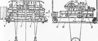
Calculation of the design and main parameters of a single-girder overhead crane with a lifting capacity of 5 tons
serega161198
May 5, 2021
- 0
982
Course project. Contains RPZ and drawings: single-girder overhead crane (general view drawing), movement mechanism (assembly drawing), hook suspension (assembly drawing). Load capacity 5 tons, crane length 10 m, load lifting height 7 m, load lifting speed 10 m/min, crane travel speed 20 m/min. Equipment classification, device
Overhead crane drawings
Types of planning
Electrical circuits of overhead cranes have a narrow specialization, being responsible for specific components of the working mechanism. The schemes themselves are of three types:
- principled;
- installation;
- marked;
- elemental.
All of them have fundamental functional features that are taken into account during the design. The circuit is created under conditions close to ideal, with a minimum of external influences.
The simplest ones are fundamental and are used when carrying out repairs and setting up the transport and lifting unit. The diagram makes it possible to accurately display a complete list of structural elements, dividing the system into chains that can be easily and quickly identified.
Options designed on the basis of mechanical drawings are classified into control and power supply circuits. Each of them has its own designations, which are expressed in thin and thick lines. The installation diagram includes all indications of the relative positions of power supplies and auxiliary components.
Each individual component of the drive electrical circuit has a special designation. Drum versions, for example, are shown in the form of sweeps, moving type contacts are drawn as rectangles in the drawings, numbered lines indicate position.
In most cases, the diagrams determine the connection sequences of all components:
- movement;
- lifting;
- protection.
But the diagrams do not indicate the proportionality of the location.
Crane repair procedure
The operation of a crane is rarely complete without repair work, which begins with the preparation of the workshop area: the removal of all unnecessary parts and things that impede the process of restoring the crane. During repairs, the unit must be disconnected from the network. The shop log records the date of repair and the person responsible for carrying it out. Workers are provided with a work permit for repairs, and special technical documentation is drawn up.
Overhead crane repair
First you need to disconnect or isolate the trolley section by placing a sign: “Caution, live.” It is important to carefully inspect the crane gearboxes and clean the inspection hatch from dirt if it has clogged the cavity of the gearbox. After cleaning the cavity, it is filled with lubricant.
During maintenance of overhead cranes, the safety system is checked, and if there are deviations, worn friction linings and hinges for the brake lever system are replaced.
In general, repairs include the following stages:
- thermal;
- metalwork;
- turning;
- surfacing;
- milling;
- gear cutting;
- grinding.
Overhead crane trolley diagram
Design features
The circuit is a rather technically complex component, consisting of several functional lines and sections. Let's consider them separately in order to better understand the principle of operation of the electric drive.
Power contactors contacts
The elements are used in situations where the crane lifts or lowers a load. In these cases, it becomes necessary to change the direction of engine rotation. This task is accomplished by switching the phases that are supplied to the stator windings of the electric motor. The function is provided by power-type contactors, each of which has two contacts of similar action. The parts are basic, their main purpose is to ensure the passage of large currents.
If we talk about DC units, their coils are designed for use in networks with constant voltage parameters. The contacts themselves are suitable for transmitting both direct and alternating currents.
But, nevertheless, in most modern designs, DC type contacts are used, as they are more reliable than AC type components. Permanent contacts also have another advantage - they have the ability to connect coils regardless of their polarity.
Many people wonder how direct current is supplied to the tap? The answer is simple - it is produced by rectifying alternating currents using diodes. A powerful transformer reduces the available values to values that are suitable for contactor coils and DC relays. Diodes are mandatory components of the design.
Overcurrent relay devices provide circuit protection against short circuits and overloads. In case of emergency situations, the relay turns off the contactor, the contacts of which supply voltage to the diodes. It is worth paying attention that the contactor is a device operating on alternating current. This indicator is stable, because when the component is turned on, the constant voltage has not yet had time to be generated.
The faucets also include several capacitors (depending on the specific type of model). They perform an important function - they reduce fluctuations in the effective voltage, because after the diodes the current comes out not 100% constant, but pulsating.
Low-power components in power circuits use AC contactors. The design as a whole is one of the most optimal, but is not without its shortcomings. One of them is the possible presence of vibrations.
Implementation of resistance
When working with a crane, the operator not only switches the direction of engine speed. The rotation speed can also be changed regularly. This is implemented quite simply - with the help of a lifting motor. The unit is asynchronous and includes a wound rotor. This indicates some differences, among which is the voltage winding in the stator. This feature is determined by the presence of a winding in the rotor (moving component). This is a key difference from traditional asynchronous motors.
There are three rotor windings, just like in the stator. The ends of the windings are connected to each other in the shape of a star, and the beginnings are connected to the rings on which the brushes move. Cables leading to resistances branch off from the last elements. They, in turn, are spiral-shaped components (in some cases, parts made of highly bent wire), made of alloys with high resistance. They are located in specially designed boxes. Containers, in turn, are connected into blocks. They are also placed in cabinets and the resistors are connected to each other in a star shape.
Container blocks
The speed of the motor is changed by short-circuiting resistance parts with contactors, which are called acceleration elements. Resistance indicators in the rotor winding circuits are minimal, current levels are maximum. On the right side, the contactors do not turn on, the resistance here is at the maximum level, and the speed, on the contrary, is minimum.
Crane electric motors operate in harsh conditions, so to increase strength and improve heat dissipation, they have a cast steel housing with a ribbed surface. The motors are equipped with waterproof insulation, which ensures their normal operation in the open air. The electric motor stator is made of thin (0.5 mm) sheets of electrical steel. The stator slots contain windings with ends brought out to clamps. The phase rotor, like the stator, is made of electrical steel. The plates are mounted on a core pressed onto the shaft.
Electrical insulating materials with different heating characteristics are used in engines; uranium engines of the MTF and MTKF series have a general Class insulation that can withstand heating up to 155 °C. For non-industrial motors operating in lighter conditions, class A insulation is used (Up to 105 °C). Previously produced crane motors of the MT, MTB, MTKV series had class B insulation that could withstand heating up to 130 °C.
Factories produce electric motors with one or two protruding shaft ends. The ends of the shafts of engines of sizes 0-3 are cylindrical, those of sizes 4-7 are conical.
The first digit in the brand of the crane electric motor indicates the conventional dimensions of the motor, taken according to the diameter of the stator package, the second digit indicates the nominal length of the stator, and the third indicates the number of poles. The stator winding of electric motors is coil, single-layer or double-layer, wound from round wire, the rotor winding (for phase rotors) is single-layer, coil. Stators and rotors are impregnated with insulating varnishes or compounds. For the stators and rotors of currently manufactured electric motors of the MTF series and the stators of squirrel-cage electric motors of the MTKF series, PET-155 winding wires of heat resistance class F are used. These motors have an increased overload capacity at relatively low currents and a short acceleration time. The beginnings of the rotor windings are connected to three slip rings on the rotor shaft. The rotor current-collecting mechanism is made with permanently adjacent brushes, which allows the motor to be reversed.
Squirrel-cage motors have a cast rotor made of high-resistivity aluminum alloy. Ventilation blades are located on short-circuited rings, which are cast integrally with the rotor. These blades create air circulation from the end sides of the engine, which contributes to better cooling of the stator windings. Basically, electric motors of the MTF and MTKF series are cooled by a fan with radial blades, which creates a stream of air along the outer surface of the frame. The fan is mounted on the rotor shaft on the side opposite to the current collector.
On cranes, asynchronous motors of the same series AOF, AOS, AOIIT with increased operating time are also sometimes used. Electric motors of the A series are manufactured in seven sizes, and each of them can have a standard mechanical characteristic for general purpose motors or a special mechanical characteristic with increased starting torque, increased slip, or a wound rotor. Series A engines are manufactured in an aluminum or cast iron casing, which is protected against the ingress of foreign objects and water, and in closed engines, dust.
In accordance with the design, the following designation of engines is established: A - protected in a cast iron casing; AO - closed, ventilated, in a cast iron body; AL - closed, ventilated, in an aluminum case. In addition to alphabetic indices, there are also digital indices: the first digit indicates the conditional number of the stator diameter, the second - the length of the stator, the third - the number of poles. For example, AOL-31-6 designates a general-purpose electric motor in a closed, blown aluminum housing, third diameter, first length, six-pole. Special motors of a single series are designated as follows: AOE - with a built-in electromagnetic brake; AOP - with increased starting torque; AOS - with increased slip
Currently, our industry is beginning to produce new electric motors of the fourth series with improved technical and economic indicators. Their marking also changes: data on the height of the rotation axis, installation and overall dimensions of the stator are entered according to the international classification system.
Starting and speed control of asynchronous motors. The electromotive force induced in the rotor of an asynchronous motor is inversely proportional to its speed. When the rotor is stationary, it has a significant value, therefore, at the initial moment of start-up, under the influence of this e. d.s. currents pass through the rotor 5-8 times higher than the rated value. To avoid overloads in the network, ballast resistors are introduced into the phase-wound rotor circuit, which limit the rotor current, and therefore the stator starting current. When additional resistors are included in the rotor circuit, flatter (softer) characteristics are obtained, which are called artificial.
If you introduce additional resistors into the rotor winding, the engine will develop the required torque at increased slip, and therefore at a lower rotation speed. The introduction of resistors with a resistance exceeding, for example, 5 times the resistance of the rotor windings, with a constant load, will increase the slip by approximately the same amount, which will be s = 0.055 5 = 0.275.
Then the rotor speed will be equal to: i= 1000(1-0.275) -725 rpm.
In most cases, squirrel-cage motors of small power are put into operation without additional devices, since their characteristics are softer than those of motors with a wound rotor.
Features of motor control of the lifting mechanism. When lowering a load, its mass promotes rotation, so the engine speed very quickly reaches synchronous speed and can even exceed it. This means that the engine slip, having decreased to zero, can become negative, i.e. the rotor will not only keep up with the rotating field, but will also begin to overtake it.
Therefore, when lowering heavy loads, an increase in resistance in the rotor increases the engine speed.
Starting resistors. To regulate the engine speed, reduce the starting current to a value safe for the engine and the network, and increase the starting torque, resistor boxes are used (Fig. 1). Each box contains several identical elements. Each element consists of a steel plate with porcelain combs placed on top and bottom. The grooves of the combs contain constantan wire or fechral tape wound onto the element, which can withstand long-term heating up to 300-400 °C. The elements are connected in series, for which purpose, during assembly, porcelain insulators and spacer tubes are laid alternately between them. The splash-proof box is closed with solid sides and a lid. The front and rear shields have louvers-type openings. External clips are located on the panel at the bottom of the drawer.
Rice. 1. Boxes of starting resistors, type NK-1; b - type NF I.
Resistor boxes are designed only for a specific motor or group of them controlled by a specific type of controller. Therefore, the external terminals of the resistor boxes are marked similarly to the controller terminals. On the crane, the box must be installed strictly horizontally. To dissipate heat between the individual drawers in the set, it is necessary to have a gap of at least 120 mm. Box covers must be reliably grounded. According to the current rules, it is prohibited to install resistor boxes in the crane cabin, therefore, if such installation was made earlier in old crane designs, then the boxes must be moved from the cabin. This requirement must be met in two cases: if they interfere with the normal work of the crane operator or if the crane is working in a hot shop.
If starting resistors of the required type are not available, they can be selected from a normalized range.
Power controllers. To turn on and regulate the starting characteristics of electric motors on overhead cranes, controllers are used. There are two types of controllers: drum and cam.
In recent years, cam controllers have been predominantly used to control electric drives. These controllers have one or two rows of cam elements consisting of movable and fixed contacts with copper jaws fixed at their ends. The movable contact of the controller rotates on an axis and is constantly pressed by its shank with a roller to the cam washer. Shaped cam washers K (Fig. 23) are mounted on a shaft pressed with electrical insulating material. Rollers P roll over the washers, changing their position depending on whether the roller is located in an area with a smaller or larger radius. In the first case, the copper contact elements of the controller are closed and pressed by spring P, in the second, on the contrary, the contacts are open. The closing and opening of contacts is accompanied by their rolling, which allows them to be cleaned of copper oxide and carbon deposits. The wear of contact surfaces in cam controllers is less than in drum controllers due to the absence of sliding friction and due to the fact that the working part of the contact, through which the current passes more or less for a long time, is removed from the place where sparks and arcs form. These features of cam controllers make them suitable for heavy duty applications. To facilitate the operation of contact parts, controllers use electromagnetic arc extinction. A special coil made of several turns of thick wire is mounted on a steel core. A current passes through the arc extinguishing coil and is broken by the controller (power circuit current). The arc and the arc extinguishing coil create magnetic fields directed towards each other, which is shown schematically in Fig. 2.
Rice. 2. Diagram of the operation of the cam controller contacts.
On cranes, controllers KKT-61A and KKT-62A of a two-row horizontal design are mainly used. In contrast to the previously used single-row vertical controllers NT-61 and NT-51, the weight and dimensions of these devices with the same current and power characteristics are 1.5 times less. The controllers are designed for a large number of starts (600-1000 per hour).
The electrical circuit diagram of the cam controller is shown in Fig. 3. This diagram shows a development of the cam washer, indicating at which of its rotation positions the contacts are closed.
The controller washers in the zero position do not touch the levers of the movable jaws and, therefore, the power circuits are open. If you move the controller handle to the first position of the Forward direction, the stator windings of the electric motor will be energized. A complete set of resistors included in the rotor circuit ensures that the engine starts at a soft characteristic at a reduced speed.
Rice. 3. Electrical circuit for controlling the motor using a power controller. 1 - engine; 2 - ballast resistors; 3 - controller.
In the second position of the controller's steering wheel, contacts P5 close, removing part of the resistance from operation. In the third and then in the fourth position, contacts P4 and RZ are closed in series, removing the second and third parts of the resistance from operation. In the fifth position, all contacts in the rotor circuit are closed, its windings are short-circuited, so the electric motor develops the highest rotation speed.
Magnetic controllers. For drives whose operating bodies are powered by DC current from AC rectifiers.
In the first position of the command controller, when lifting, contactors B, KP and T, relays 1RU, 2RU, and then contactor P are activated. As a result, the engine is connected to the network, released, part of the resistors in its rotor circuit is bypassed and the engine accelerates with preliminary removal of the slack in the rope. In the second and third positions of the handle, contactors 1U and 2U are activated, respectively, which makes it possible to obtain intermediate speeds. When the 2U contactor is turned on, the 1RU coil is turned off, as a result of which, with a time delay, the 1RU contact in the circuit of the ZU and 4U coils is closed. In the fourth position of the handle, the charger contactor is activated, and the 2RU coil is turned off, after which the 4U contactor is turned on with a time delay. The engine switches first to the intermediate, and after acceleration to the lifting operating characteristic.
When the handle is quickly switched from the zero to the fourth position, the engine switches to an operating characteristic with an automatic time delay using relays 1RU and 2RU.
When the controller handle is quickly moved from the zero to the fourth position during descent, the engine also achieves operating characteristics with an automatic time delay using relays 1RU and 2RU. When lowering loads with low mass, when the friction loss in the mechanism is greater than the engine torque, the latter will run idle, and heavier loads will be lowered at a supersynchronous speed. To reduce the lowering speed, move the controller handle to the third position, as a result of which the single-phase braking contactor is activated. In this case, the engine operates in electromagnetic brake mode. A further reduction in speed is obtained in the second and first positions of the handle, when the motor connected to the network by contactor B operates in back-to-back mode.
The magnetic controller type TA is made according to a symmetrical circuit. Here, the possibility of free run-out of the engine in the zero position of the controller is provided, while mechanical braking is carried out in any of the other positions of the command controller handle, when the limit switches are activated or when the AK button is pressed. The RN relay and the T contactor do not turn off in the zero position. In this scheme, the counter-switching mode provides braking of a moving crane or cargo trolley. When the engine rotates, for example, in the Forward direction, the command controller is switched to one of the Reverse positions. Contactor H is activated first, as a result of which current reappears in the stator and rotor circuits, including the ballast resistances.
Rice. 5. Magnetic controller type TA. a - electrical diagram of the power section; b - diagram of control circuits.
Since the direction of rotation of the magnetic wheel is opposite to the direction of rotation of the engine, the voltage generated in the rotor increases, as a result of which the RN relay connected to the ballast resistance is activated and interrupts the circuit of coils P, 1U, 2U, ZU. The engine will operate in back-on mode with full resistance in the rotor circuit, regardless of the position of the controller. As the rotation speed decreases, the voltage at the terminals of the RP relay coil decreases, and at /g the relay turns off. To prevent spontaneous movement of the crane in the opposite direction, the command controller must be switched to the zero position.
Command devices. To operate magnetic controllers, contactors, protective and reversing panels, devices are used that bear the general name of command devices. The number of command devices includes command controllers, universal switches, limit and emergency switches.
The housings and covers of the command devices are usually cast from cast iron or aluminum alloy. Levers or handles that have a locking device are located outside. The shapes and sizes of the levers on the handles depend on the type and location of the device. For example, the KP-1400 and KP-1500 command controllers are built into the crane operator’s chair, so they have an elongated handle with a rocker drive; Limit switches have levers with or without self-return. In Fig. Figure 27 shows the command controller. The contact system of the command controller differs from the contact system of the power controller in that it is made in the form of a contact bridge located on the lever of the cam element. Silver plates are soldered onto the contact surface of the bridge, resistant to oxidation and creating reliable contact even with low spring pressure of the cam element. The cam element rotates under the action of a cam washer mounted on a shaft with a locking device. Just like power controllers, command controllers are shown in expanded form on electrical diagrams, where it is indicated in which fixed position of the cam shaft handle the contact bridge closes the circuit.
If command controllers have several contact bridges, then the limit switch usually has one or two such bridges. On cranes, a limit switch of the KU type is widely used, which provides various contactor closure schemes. A KU type switch has two contacts, which can be normally open, normally closed, or one can be normally closed and the other can be normally closed. The mechanism of the KU type lever switch is housed in a stamped steel case, closed on all sides, and has one lever on the outside, which is acted upon by stops installed in the extreme positions along the path of the moving mechanism. There are washers attached to the switch shaft. When the shaft is rotated, an insulating (carbolite) lever with contact bridges 6 closes (or opens) fixed contacts mounted on the insulating stand. The lever, under the action of a spring, is constantly pressed against the cam washers using a roller. In this case, the contacts are open. In order for the contacts to be closed in the initial position, the lever roller is moved to the axis, and the spring to position K. The position of the cam washers relative to the axis is changed by turning them and fixing them with screws. The need to change the position of the washers arises when rearranging the drive lever mounted on the end of the shaft, and when changing the contact closure pattern. The locking ratchet and the pawl 8 connected to it with a spring are designed to return the operating lever of the switch to its original position. In addition to the considered switch, the cranes use a 52 spindle switch of the VU-250A type. Such switches are installed to limit the lifting height of the load. In this case, the contacts are closed and opened by turning the low-speed shaft of the worm gearbox, which has a gear ratio of 1:50. When the closing roller runs against the protrusion of the contact lever, the latter slowly turns and is then locked in the closed position by the pawl. The entire path of closing the moving contact corresponds to 5/6 revolutions of the shaft with washers or 42 revolutions of the drive shaft. The switch returns to its original position after activation when the drive shaft is turned 1.5 turns.
Rice. 6. Command controller. 1 - body; 2 - cam drum shaft; 3 — gear sector; 4 - handle; 5 - cams that change the number of locking positions of the handle; 6 — lever of the locking device; 7 — spring of the fixing device; 8 — lock washer; 9 — cam elements; 10 — cam washers; 11 - rail for fastening cam elements.
Rice. 7. Limit switch type KU. a - operating principle; b - general view with the cover removed.
The VU-250A switch has two bridges and can be configured to break circuits in two positions, which allows you to limit both the upper and lower positions of the hook suspension. Switches VU-150A are similar in design to switch VU-250A, but can only break one circuit. Their permissible continuous and breaking current is 20 A. KU-701 switches have one circuit, their permissible current is 10 A.
Universal switches are made up of separate contact sections, isolated from one another by plastic walls. The most commonly used universal switch is UP-5311. The first two digits indicate that the device is made in an open, unregulated design, the next two digits indicate the number of sections (in this case, 11).
Emergency manual switches VU-220 are used to instantly break the main control circuits if it is necessary to urgently stop the entire crane; they are performed with normally closed contacts.
Protective and reversible panels. Protection panels are designed for maximum and zero motor protection and are used in conjunction with cam and magnetic controllers. The panel is located in a metal cabinet in which a three-pole switch with an external handle and a line contactor are mounted on an insulating asbestos-cement board. The panel is also equipped with maximum relays acting on the line contactor, control circuit fuses, a test switch, and a start button for the electromechanical lock.
An electromechanical lock assembled from commercially available products for a door lock and a packet switch is shown in Fig. 29. A mechanism was taken from the door lock. The body, coupling, cover and metal thrust plate are made of textolite, which serves to limit the rotation of the contact washer by 90°. A drive strip passes through the shaped hole of the thrust metal plate.
Rice. 8. Electromechanical lock.
The details of the electrical part of the lock are taken from a standard package switch for a current of 25 A.
The lock is installed in the wall of the protective panel cabinet in such a way that only the end of the mechanism protrudes outside. The rest of the lock fits inside the padlocked panel. Using two clamps, the lock is connected in series to the main contactor coil circuit. The normal position of the lock contacts is open. To turn on the contactor, you need to insert the key into the hole of the mechanism and, turning it clockwise 90°, close the contacts.
Instead of a contact lock, it is allowed to install a lock with an individual key, a locking switch, a machine or a switch in the off position. The key should be removed from the lock only when the switch, machine or circuit breaker is turned off and locked in this position. This requirement is met by protective panels of the PZKB-160 and PZKB-400 types.
Rice. 9. The principle of operation of the contactor, a - alternating current; b - direct current.
Contactors. The main device of crane protective and reversible panels and magnetic controllers is a contactor - a device for turning on and off electric current at a distance. In Fig. Figure 30 shows the appearance of the contactor and the principle of its operation. On an isolated axis 1 of square cross-section, the bearings of which are not shown for simplicity, movable working contacts, an electromagnet armature and a traverse for block contacts are installed.
In Fig. 9, a shows a simplified diagram of starting and stopping a squirrel-cage asynchronous motor with push-button control using a contactor. The power circuit is connected directly to the motor and is indicated by thick lines. The control circuit (thin lines) shows two buttons - the one that turns on Start and the one that turns off Stop. Starting is done as follows. When the Start button is closed, current flows from wire IIX through the electromagnet winding to wire L3. A closed circuit is formed. The anchor is attracted and turns the axis, while the working contacts and the upper block contacts are simultaneously closed. The latter bypass the Start button and allow you to disable the power button. To turn off the engine, simply open the control circuit by pressing the Stop button. The contacts will fall off under the force of the device's own weight.
The design of a DC contactor is shown in Fig. 9. When current passes through the coil winding, the armature (the moving part of the magnetic circuit) is attracted to the stationary core. In this case, the armature, turning together with the caliper and the movable contact mounted on it around the axis, brings the movable contact into contact with the fixed contact. In this case, the contacts, first connecting with their upper parts, come into further contact and move relative to each other, as if rubbing in. The arc is extinguished in the spark chamber. An arc suppression coil is connected in series with the main contacts. The magnetic field created by this coil is directed in such a way that the arc (like a conductor carrying current) is pushed upward according to the right-hand rule. The current from the moving contact is removed using a flexible conductor. The contactor is mounted on the plate.
Since 1971, the industry has been producing AC contactors of the KT-6000 series. The permissible switching frequency of these contactors is at least 600 per hour. Arc extinguishing is electromagnetic, which allows switching on, reversing and switching off stalled motors, including those with a squirrel-cage rotor.
The blocking contacts of the contactor consist of a pressed housing, fixed contacts and a traverse with bridge-type moving contacts. The traverse moves in metal guides under the action of a cam mounted on the contactor shaft.
Relay. To protect the electric drive from overloads and voltage drops, intermediate and thermal relays, current and voltage relays, and time relays are used.
Intermediate relays are used in electrical circuits in cases where the number of block contacts of the main devices is not enough to implement the electrical circuit for controlling the crane. They are made with front and rear connection of wires.
To protect the windings of electric motors operating in long-term mode from overheating, thermal relays of the TRI and TRP types are used. TRT. In some cases, such relays are included in the set of electrical devices, for example magnetic starters.
A bimetallic element is a two-layer metal plate made of two metals having different linear expansion coefficients. The wire spiral of the electric heater is connected in series to the electrical circuit, x. e. into the engine protection circuit. The closing or opening of this circuit is carried out by the contacts of a special electromagnetic switch (not shown in the diagram). The opening contact of a thermal relay is included in the coil circuit of this switch. During prolonged overload of the motor, when the current in the heater increases noticeably, the bimetallic element bends and releases the latch, which rotates under the action of a spring and opens the contacts. The circuit of the coil of the electromagnetic switch is broken, its contacts open and the engine is disconnected from the network. After cooling the element, press the button to return the relay to its original position. These relays are manufactured with self-reset or manual return to the original position.
Rice. 10. Overcurrent relay.
As maximum current protection in the power circuits of overhead cranes, instantaneous relays REO-401 and RE-571T are used.
Flexible cables
The motors of cranes are located on a platform of a rotating structure, which is located on a trolley that moves along the bridge beams of the cranes. Other components are installed on the bridge beams. The motor is connected to the above-described components precisely by flexible cables, which are suspended on a cable. As the cart moves across the bridge, the cable connectors follow. When bending during operation, wire strands can break, which ultimately leads to malfunctions.
Modifications have also been implemented, along the bridges of which additional trolleys move. When the cart moves, the current-collecting elements attached to the cart travel along with the main component. Thanks to this, voltage is supplied directly to the cart from the bridge.
Flexible cables on a finished structure
RN type contactor and controller
So, the controller is a precise unit that directly controls the crane. The control element washer number is indicated separately on the design. There are other numbers on the case, as well as broken lines indicating the current position of the controller lever. A black dot, for example, identifies a contact closing in a selected position. If there is no point, then the contact is accordingly open.
The second required element is the LV contactor, the functionality of which allows it to be called a relay. The capabilities of the component are truly wide; in particular, they include starter functionality. The part is equipped with a coil through which current passes and, as a result, the contacts close or open.
The diagram shows that when the contactor is in the “zero” position, the connecting elements are closed and voltage is supplied to the contactor LV coil. If the contactor is triggered, the unit activates the contact to “pick up” itself. This component is distinguished by the fact that it can operate uninterruptedly in other relay positions.
Disabling the controller is also quite simple - by turning off devices 1 and 2 RU. When starting a relay with a maximum current MP when the electric motor is overloaded. Contactors at 1V are started when the crane structure is lifted. Even if, when the LV is triggered, the device does not turn off in situations where the bypass circuit does not open. The chain also includes contacts from a VKG2 type limit switch, which is triggered when the weight is raised to too high a height. Relay element K3 is also present, and it is always in the closed position during normal operation of the tap.
Note that the above relay relates more to the protective systems used in connection with the technological features of cranes with traverses. With their help, the load can be lifted until the limit switch is activated. The light on the diagram signals the operator that the controller is in the zero position or that the LV contactor is activated.
LV controller and contactor
Now let’s look at the most common types of networks in more detail.
Operational chain
The RN type contactor is responsible for turning on and off the operating circuit of the lifting mechanism. The chain is an element that supplies voltage to the contactor coils. As a rule, the components operate with a voltage of 220 volts, but there are also modifications with 110V coils.
The design of the circuit also includes parts responsible for performing various functions:
- movement;
- cart transportation;
- platform rotation.
All these devices work with LV relay devices. The network includes two series contacts in case one of these elements becomes welded to the fixed contact due to high currents.
In situations where the operating circuit is not energized, there is no need to turn it on. When carrying out the initial supply of voltage to the OC, the machine does not start instantly, no matter what position the controller lever is in. That is why the crane operator must first put the lever in its original position so that the voltage gets into the circuit.
Circuit of magnets with disinhibiting action
The lift motor rotor is locked by the brakes when this component is turned off. In order to ensure rotation of the rotor, it is necessary to trigger the brake release electromagnet, which will quickly release the brake pads.
The component triggers the electric magnet of the T contactor. Next, the magnet is connected in series to the RD-G resistance, which can additionally be bypassed using the 1T contactor. This function allows the overcurrent relay to continuously monitor the magnitude of currents passing through the coils of electric magnets.
This was done to ensure control of current values using relay RT. This is implemented so that a certain level of voltage passes through the electromagnet coil to avoid burnout. If the current nevertheless exceeds the set value, then the RT relay turns off the 1T element, and the shunt resistance opens. As a result of these reactions, the current passing through the coil of the magnetic part decreases.
Contactors T and 1T on crane installations are implemented in the efficiency type. 1P fuses are located above a similar 2P element. If a short circuit occurs in the magnet circuits and the 1P fuse burns out, the operational circuit of the contactors will be de-energized. The lifting mechanism stops and after this, relays 1 and 2 of the switchgear, as well as the pH contactor, are turned off.
Features of braking systems
Old hydraulic brake systems tend to leak and have maintenance and environmental problems. They can be replaced with modern “brakes by wire”.
AC Thruster Foot Brake Packages that solve these problems. At the same time, a similar braking effect is provided, which is inherent in working with hydraulic brakes.
Fully enclosed brakes are also available in modern design to match performance. OE brake dimensions - often available at a lower price.
Modernization of a double-girder overhead crane with a lifting capacity of 10 tons
Alyona
June 22, 2020
- 0
1 222
Development of a technical proposal for the modernization of a double-girder overhead crane with a lifting capacity of 10 tons. This course work describes the device and operating principle of an electric double-girder overhead crane, and patent research was also carried out.
Overhead crane drawings / Cranes
Operating principle
Cranes have two functions: lifting and lowering. These manipulations are also assigned functions in the electrical circuits of the drive.
Lifting principle
Crane lifting diagram
4 lifting modes are implemented, which have common and distinctive characteristics. The release magnet contactors T and T1 are activated by parallel pressing of the brake pads. Power contactors 1 and 2B are turned on, driving the electric motor. Next, contactor P, which is responsible for acceleration, is started. This component is also responsible for ensuring minimal engine acceleration (in the first stage).
First, washer 7 closes, triggering 2B. From the same washer, voltage is supplied further to the 2nd washer of type 1B, and then only to the 3rd washer of type P. When implementing transitions to modes 2–4, sequential activation of acceleration contactors is observed: 1 and 2U. only in the fourth mode are versions 3 and 4U enabled.
The principle of descent
The process is an order of magnitude simpler than lifting, because when lifting a load it is necessary to use a certain amount of energy, but when lowering it, it is spent in small volumes or not at all. The object lowers on its own, using the well-known force of gravity. The only thing that may require energy is to ensure that the load is slowed down during descent, in order to avoid strong acceleration.
4 key modes have been implemented to ensure reliable descent, let’s take a look at them.
First mode
When this procedure is implemented, the controller washers 3, 2, 9 and 8 are closed. The third washer starts the acceleration contactor P, and the second – the power contactor 1B, which works exclusively for lifting. Energy is supplied to the above washers through the ninth washer and the contact elements of the RB (in some modifications 1T).
In situations where 1T is turned off, no voltage is supplied to the RB coils. Based on this, you can guess that other functional components do not start:
- Electrical engine;
- brake mechanism.
When the operator presses the BH2 key, components T and T1 will start, followed by devices 2B, RB, 1B and, finally, P. As a result, the electromagnetic field in the stator will work to lift the load. The explanation for this is simple - mode 1 is designed to effectively slow down a descending object. This is much more convenient and cost-effective than using conventional brake pads, which significantly reduces component wear. This phenomenon is also known as countercurrent stopping.
Mode two
In essence, the solution algorithm is similar to the first, with the exception of the operation of the P-type acceleration contactor. As a result, the load intensity decreases.
Third mode
When implementing this mechanism, 1B and P are not used; instead, 2H and 2B are actively used. 1T is also included in the work, through the RB, the contact of which triggers the T-contactor. Further along the chain, the contactor responsible for acceleration 1U is turned on.
By performing braking in this mode on 2 stator windings at once, a phase with the same indicators is supplied. The 3rd phase does not take part. This method of connecting the stator winding will not allow the rotor element to brake, no matter where the revolutions are made. It works by providing descent, while the stator simultaneously implements braking.
Mode four
First, the 2B contactor stops, and then the 1H power contactor is turned on. Three phases are supplied to the electric motor at once, and the power unit works to reduce the load. Contactors 2, 3 and 4 also come into operation, providing acceleration. According to experts, this mode is exactly the opposite of the last “lifting” mode.
Everything about the construction of an overhead crane: from the load trolley to electrical equipment
In the 80s, 6-7 thousand overhead cranes were produced annually in the USSR. In the 2000s, their production in Russia decreased to 1000-1500 units of equipment.
The simple design of an overhead crane makes it possible to widely use load - lifting machines type in enterprises of various sizes - from small auto repair shops to large metallurgical plants or thermal power plants.
Two ways to support a crane runway
An I-beam span has upper and lower horizontal chords. Supporting ones are placed on the upper one, and hanging ones are attached under the lower one:
- Support - mounted with wheels on the rails from above. The load-bearing capacity of the support GPM is maximum (up to 500t), but the construction of a crane trestle or supports requires financial costs.
- Suspended - hooked to the lower shelves of the crane runway. This type of support is easy to install and has a low cost. The small lifting capacity (up to 8 tons) is compensated by the low height of the structure, which is why the size of the working area is larger than that of support cranes. Suspended cranes can be installed on part of the workshop. It is possible to dock cranes (butt lock) and move trolleys from one crane to another.
Device designs vary. They can move translationally or make revolutions around the vertical axis (chordates, radials and rotations) of the PMG.
Overhead crane design
Depending on the number of main beams, the GPM design can be:
- single beam Used in small industries, it can be suspended or supported. Capacity: 8 tons. Use: in large production workshops, in the automotive and metallurgical industries. Span length - up to 60m. A cargo trolley may have an auxiliary lifting mechanism in addition to the main one.
Type of bridge PMG drive
The drive mechanisms of bridge PMGs can be manual or electric.
- Manual drive . This overhead crane has a worm hoist as a movement mechanism. Manual hydraulic and hydraulic machines are used for lifting relatively small loads when performing auxiliary or repair work.
- Electric drive . Electric hoists serve as devices for lifting and moving loads. The PMG bridge also moves with the help of electric motors; they transmit rotation to the running wheels either through gearboxes or through a gearbox and transmission.
What does an overhead crane consist of?
The general structure of an overhead crane is a single- or double-girder bridge and a load trolley that moves along it.
https://www.youtube.com/watch?v=9svnGhKK7Vk
Electrical equipment and main components and mechanisms are placed on the bridge and on the trolley.
Brake system
The standard braking system for bridge PMGs is block or disc-block.
If the trolley speed is ≤32 m/min, the moving mechanisms do not need to be equipped with brakes. Under these conditions, the PMG will be able to brake on its own without exceeding the braking distance.
Functionally, the braking devices of cranes are locking - to stop the device - and release - slowing down the descent.
Brakes can be open or closed types. The lifting mechanisms of cranes are equipped with closed brakes - in the normal position the mechanisms are braked, the brake is released only when the engine starts.
Lifting mechanisms for cranes moving dangerous goods: molten metal, explosives, toxic substances, acids, have 2 brakes that operate autonomously.
Closed type brakes are used in hydraulic and mechanical engineering because they are more durable than open ones and their failure can be easily noticed.
In some cases, open brakes are mounted in addition to closed ones (as auxiliary ones) to increase the speed and accuracy of load placement.
Lifting mechanisms
The mechanism for lifting and lowering the load is also located on the crane trolley.
It consists of a drive electric motor, transmission shafts, a horizontal gearbox and cargo cables with a winding drum.
For work with loads >80 t, additional overhead crane gearbox or reduction gear. To increase the traction force, a chain hoist is used (most often a double multiple).
Overhead crane gearbox, its purpose and design
Functionally, cylindrical crane gearboxes can be divided into:
- lifting gear reducers;
- trolley motion reducers;
- axle motion reducers.
The gearbox can have 2 types of design: deployed and planetary .
Reducers of the deployed type, equipped with cylindrical wheels, are more popular. Repair and maintenance of mechanisms of this design are simpler and cheaper.
Crane tracks for overhead cranes
When constructing a crane track, railway rails P18, P24, P38 (narrow gauge) and P43, P50 and P65 (for wide gauge) are used as crane and trolley rails.
They also use special crane rails KR50, KR70, KR80, KRYUO, KR120, or square steel guides with rounded edges (for mechanisms with lifting capacity ≥ 20t).
I-beams are used as crane tracks for suspended type GPM.
Attachments of rails to beams must prevent movement of the rails and must allow the quick replacement of worn rails. Their ends are connected with double-sided plates and bolts or welded.
Electrical equipment
Special, increased requirements are imposed on the electrics of bridge PMGs, which is due to intense operating conditions.
In 1 hour, hundreds of switching on, switching off and overloads associated with acceleration and braking of the device as a whole or the cart can be performed.
Innovations in braking systems
Modern braking schemes use modernized brakes, the efficiency of which has significantly improved, and the brake linings have a longer service life. The components work together with AC frequency regulators or digital DC controllers.
In many cases, the support bearings in the swing arms have been replaced with self-lubricating bearings. And composite bearings are shock resistant, unaffected by dirt or other contaminants, and can operate in harsh environments.
Functionality of relay devices
The key relays in the design of the lifting mechanism drive circuit are two models: 1 and 2 RU. They are used in conjunction with another basic component of the RB, but the functionality is different. One example is when, when operating in lifting mode 4, the accelerating contactors are started: 3U and 4U. If descent is carried out in mode 4, then as many as three contactors come into operation, and version 2U is added.
This is due to the design of the controller, which has 4 operating modes for each side. In order to avoid sudden accelerations, the activation of the start contactor must be separated in time. This is what relays 1U and 2U do.
As you can see, the fundamentally implemented scheme makes it possible to install the crane and simplify service processes. Full compliance with the manufacturer’s parameters will significantly reduce the negative effects on the crane mechanisms. The design of devices used in the circuits is regularly modernized.